1
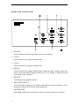
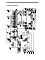
Table of Contents
FEATURES..................................................................................................................... 1
SPECIFICATIONS ......................................................................................................... 1
FRONT PANEL INDICATORS AND CONTROLS ......................................... 1
CONTROLS........................................................................................................ 1
REAR PANEL CONNECTORS......................................................................... 1
OTHER................................................................................................................ 2
CONTOLS / CONNECTORS......................................................................................... 2
FRONT PANEL FUNCTIONS........................................................................... 2
REAR PANEL CONNECTORS......................................................................... 4
INSTALLATION ............................................................................................................ 5
INSTALLATION PROCEDURES ..................................................................... 5
BEFORE OPERATION ...................................................................................... 5
TUNING.......................................................................................................................... 6
USING THE BARGRAPH ............................................................................................. 7
NOTES ............................................................................................................................ 8
TECHNICAL ASSISTANCE ......................................................................................... 8
METER CALIBRATION ............................................................................................... 9
METER CALIBRATION PEOCEDURE........................................................... 9
YOUR NOTES................................................................................................................ 10
SCHEMATIC DIAGRAM.............................................................................................. 11
HFT-1500 Digital Antenna Tuner with Roller Inductor
Owner's Manual
VECTRONICS
HFT-1500 Digital Bargraph Antenna Tuner
FEATURES
The Vectronics HFT-1500 optimizes the performance of your antenna and transmitter or
SWL receiver by providing adjustable impedance matching. The HFT-1500 also
measures the Power and Standing Wave Ratio (SWR), which allows you to tune the
indicted SWR to the lowest possible ratio for the selected transmit frequency. The HFT1500 also features a precision frequency compensated lighted dual movement SWR
meter. Included with the tuner is an unique Digital Bargraph Display that enables you to
analyze peak SSB power measurements. Level and Delay controls are front panel
adjustments.
SPECIFICATIONS
FRONT PANEL INDICATORS AND CONTROLS
Meter ..................................... Dual movement D'Arsonval lighted cross needle Power and
SWR meter. RF directional coupler sensing head for the
internal wattmeter circuit. Meter is lighted.
Bargraph Display................... 21 segment LED display to indicate 100% peak reading
with adjustable level and delay.
CONTROLS
Input Tuning.......................... Continuous rotation 4.5 kV capacitor.
Antenna Tuning..................... Continuous rotation 4.5 kV capacitor
Inductance ............................. 28 uH roller inductor with #10 bright tin plated wire and
Delrin/Teflon body.
Antenna Switch Selector ....... Six position ceramic coax switch: COAX 1, Tuned and
Tuner Bypass, COAX 2, Tuned and Tuner Bypass, Bypass
and Balanced Antenna.
Power Range Switch ............. Two position: 300W/3000W
Inductor Control/Tune........... Dual nylon gear driven, Veerderoot precision 5 digit
mechanical counter for accurate resetability.
REAR PANEL CONNECTORS
Coax 1 ................................... SO-239 connector
Coax 2 ................................... SO-239 connector
1
HFT-1500 Digital Antenna Tuner with Roller Inductor
Owner's Manual
Bypass ................................... SO-239 connector
RF Input................................. SO-239 connector
Balanced Line........................ Dual high voltage Derlin terminal post; includes 4:1 2.5
kW voltage balun (Ruthroff type).
End-Fed Wire ........................ High voltage Derlin terminal post.
OTHER
Frequency Coverage.............. 1.8-30 MHz; continuously tunable.
Power Maximum ................... 1000 Watts single tone continuous; 2 kW PEP SSB.
Dimensions............................ 5.5" (140 mm) H x 12.5" (318 mm) W x 12" (305 mm) D
Weight ................................... 10 lbs. (4.5 kg.)
CONTOLS / CONNECTORS
FRONT PANEL FUNCTIONS
1. TRANSMITTER
Continuously adjustable input capacitor
2. POWER / SWR METER
Dual needle meter displays FOWARD and REFLECTED Power in Watts.
2
HFT-1500 Digital Antenna Tuner with Roller Inductor
Owner's Manual
The SWR in measured where the two needles intersect on the red scale.
3. ANTENNA
Continuously adjustable output capacitor.
4. DIRECT-TUNED MODE SWITCH
Six-position rotary switch an output coaxial connector.
1. DIRECT BYPASS selects BYPASS COAX connector bypassing the impedance
matching circuit but providing SWR, FORWARD, and REFLECTED power meter
readings.
2. DIRECT COAX 1 selects the COAX 1 connector bypassing the impedance
matching circuit but providing SWR, FORWARD, and REFLECTED meter
readings.
3. DIRECT COAX 2 selects the COAX 2 connector bypassing the impedance
matching circuit but providing SWR, FORWARD, and REFLECTED meter
readings.
4. TUNED COAX 1 selects the COAX 1 connector through the impedance matching
circuit.
5. TUNED COAX 2 selects the COAX 2 connector through the impedance matching
circuit.
6. TUNED WIRE/BAL selects the END FED WIRE connector through the
impedance matching circuit. For balanced antennas, the wire antenna post is
externally connected to the balanced line.
5. INDUCTOR
28 uH continuously variable Derlin roller inductor driven by a crank handle. A geardriven precision mechanical counter is coupled to the crank handle.
6. RANGE SWITCH
Two-position push button switch selects the range (300w or 3kW) of FOWARD and
REFLECTED Power displayed on the power meter.
When the METER button is out, the FOWARD meter scale reads 300 watts full scale
and the REFLECTED meter scale reads 60 watts full scale. When the METER button
is in, the FOWARD meter scale reads 3000 watts full scale and the REFLECTED
meter scale reads 600 watts full scale.
7. LAMP
A two position switch selects whether the meter is illuminated.
8. DIGITAL BARGRAPH DISPLAY
A 21 digit LED bargraph which display is capable of responding to SSB signals or
CW. The sensitivity of the display is controlled by the LEVEL control on the front
panel. The delay of the SSB signal is continuously variable by the DELAY control.
3
HFT-1500 Digital Antenna Tuner with Roller Inductor
Owner's Manual
REAR PANEL CONNECTORS
1. RF INPUT
Coaxial connector for input from SWL receiver or transmitter.
2. COAX 1
Coaxial connector for output to Antenna One.
3. COAX 2
Coaxial connector for output to Antenna Two.
4. BYPASS
Coaxial connector for output to dummy load or third coax output. Bypasses tuner, but
meter circuits and digital bargraph remain active if AC adapter is connected to the
jack located on the rear panel.
5. GROUND
Post/Wing-nut type ground connector.
6. BALANCED OUTPUT
Two Derlin High Voltage post for output to RF balanced twin-lead antennas. (Note
that jumper must be used as shown by the dotted line.)
7. END FED WIRE
Derlin High Voltage post for output to a single-wire antenna. (Do not use jumper.)
4
HFT-1500 Digital Antenna Tuner with Roller Inductor
Owner's Manual
INSTALLATION
Carefully unpack your HFT-1500 from the packing carton and inspect it for signs of
damage. If any damage is apparent, notify the transportation carrier or dealer
immediately. We recommend keeping the packing carton for moving, storage, or
reshipping the tuner.
Select a location for the HFT-1500 that allows the connectors to be free of any possible
contact during operation.
WARNING: SOME BALANCED OR END-FED ANTENNAS WILL PRODUCE
HIGH RF VOLTAGES AT THE BANANA CONNECTORS. RF
BURNS MAY RESULT IF TOUCHED DURING TRANSMISSION.
INSTALLATION PROCEDURES
1. Connect a coax cable from your transmitter or receiver to the RF INPUT connector on
the rear panel. Keep the cable as short as possible. If you use a linear amplifier,
connect your transmitter to the linear amplifier output to the HFT-1500. Do not use
more than 1000 watts average (single tone) through the tuner.
2. Connect coax cable(s) from your antenna to COAX 1 or COAX 2 connectors on the
rear panel. These connectors are either direct from the transmitter or through the
tuned circuit depending on the setting of the OUTPUT SELECTOR switch on the
front panel.
3. If you are using a balanced feed antenna, connect a balanced line to the BALANCED
OUTPUT connectors and jumper banana jack (8) with lower jack (7) as shown by
dotted line.
4. If using a single wire antenna, connect it to post (7) without installing jumper.
5. Connect a dummy load to the BYPASS (4) connector using a coax cable. This lets
you select the dummy load from the OUTPUT SELECTOR switch. Any antenna that
does not require the use of an antenna tuner may be connected to the BYPASS
connector, if desired.
BEFORE OPERATION
1. To avoid possible damage to the HFT-1500, set TRANSMITTER, ANTENNA,
INDUCTOR, and POWER RANGE switches as outlined in the next section before
applying transmitter power. (Tuning Section)
2. Begin tuning with your transmitter set at a low power setting (50 to 100 W)
WARNING: DO NOT OPERATE THE HFT-1500 WITH THE COVER OFF!
5
HFT-1500 Digital Antenna Tuner with Roller Inductor
Owner's Manual
TUNING
1. Select the band and frequency of desired operation.
2. Set TRANSMITTER, ANTENNA, and INDUCTOR controls to the suggested
settings before applying transmitter power. Actual settings may vary from antenna to
antenna.
BAND/
ANTENNA
Actual
INDUCTOR
Sug.
Actual
TRANSMITTER
FREQUENCY
Sug.
Sug.
160 M / 1.8 MHz
9.0
70
8.5
75 M / 3.75 MHz
7.0
280
7.0
40 M / 7.15 MHz
3.0
325
3.0
30 M / 10.125 MHz
2.5
350
2.5
20 M / 14.175 MHz
1.5
360
1.5
17 M / 10.118 MHz
1.0
380
1.2
15 M / 21.225 MHz
1.0
380
1.0
12 M / 24.940 MHz
1.0
390
0.6
10 M / 28.850 MHz
0.6
390
1.0
Actual
3. Set up your transmitter to a low power output. If your transmitter has a TUNE
position, select that position.
4. If you use a linear amplifier, set it to STANDBY. Do not use the linear amplifier
until the HFT-1500 is tuned.
WARNING: DO NOT EXCEED 1000 WATTS AVERAGE (SINGLE TONE).
5. Set POWER RANGE switch to 300W (with meter button out).
6. Set OUTPUT SELECTOR switch to BYPASS, or the position matching your antenna
connection. To tune your antenna, the switch selection must be set to: COAX 1
TUNED, COAX 2 TUNED, or WIRE (BALANCED ANTENNA). Selecting COAX
1 DIRECT, COAX 2 DIRECT, or BYPASS, bypasses the tuning section.
7. Rotate the TRANSMITTER, ANTENNA, and INDUCTOR controls for maximum
noise or signal as heard on your receiver.
8. Key your transmitter and adjust the power level for a reading of 50-100 watts on the
FORWARD scale. Adjust the TRANSMITTER, ANTENNA, and INDUCTOR
6
HFT-1500 Digital Antenna Tuner with Roller Inductor
Owner's Manual
controls for a minimum REFLECTED reading while maintaining a FORWARD
reading of 50-100 watts using your transmitter power control.
9. Read the SWR on the red scale at the point where the two needles intersect. Repeat
step 8 until the lowest SWR reading is obtained. The SWR should be 2:1 or lower.
Note: This procedure takes patience the first time. The TRANSMITTER and
ANTENNA controls vary the capacitors and provide fine adjustments. The
INDUCTOR control provides coarse adjustment.
10. When you have tuned your antenna to the best SWR, record the settings of the
TRANSMITTER, ANTENNA, and INDUCTANCE controls on the previous chart for
future reference. When you retune, use these settings as your starting point.
USING THE BARGRAPH
1. Plug in the AC adapter provided with your tuner into jack located on the back panel.
2. In the Tuning Section after completing the tune-up sequence, key your transmitter
through the tuner into the dummy load (e.g. DL-650; DL-500). Adjust for a meter
reading of 100 Watts Forward (at this time the SWR will have been adjusted for
minimum value as outlined in the Tuning Section).
3. Rotating the LEVEL control activates the bargraph and the segments will illuminate
progressively as the LEVEL control is increased. If your cross-needle meter is
reading 100 Watts as indicated in (2) rotate LEVEL control so that the last LED (red)
illuminates. This signifies that the 100 Watt average single tone reading on the
cross-needle meter display is identical to the power reading of 100 Watts single
tone on the digital display. Without any further adjustment of the LEVEL control,
switch your transmitter to SSB and speak normally into the microphone and you will
notice that the cross-needle meter will read approximately 30-40 Watts and the digital
display will show an output of 100 Watts PEP when red LED ignites while you are
speaking. This will confirm that the cross-needle meter reads 30-40 Watts average
assuming you started with the 100 Watts single-tone as described above and the
digital display will read voice peaks of 100 Watts (100 Watts PEP).
Note: All cross-needle meters read average power when you are using the transmitter
in the SSB mode. Some cross-needle meter displays are capable of peakreading but will read 20% low because of directional coupler driver
impedance problems.
4. Once satisfied you are getting the right results in (3), while you are speaking into the
microphone with the DELAY control fully counter-clockwise, the forward peak
indication on the meter will be as quick in response as the delay. If this is not a
desirable condition, rotate the DELAY control counter-clockwise until the desired
amount of DELAY is introduced in the display. The forward fast attack time is not
affected by the DELAY control.
7
HFT-1500 Digital Antenna Tuner with Roller Inductor
Owner's Manual
NOTES
1. An SWR or 1:1 is best, but an SWR as high as 2:1 may be acceptable. Check you
transmitter manual for details.
2. If you cannot get an acceptable SWR, lengthen or shorten you antenna and/or
feedlines and retune.
3. If you get low SWR readings at more than one setting, use the setting that:
•
•
•
Gives the highest FORWARD power reading.
Gives the lowest REFLECTED power reading.
Uses the largest capacitance (highest number) on the TRANSMITTER and
ANTENNA controls.
4. Any time a new or different antenna is connected, it is necessary to repeat the tuning
procedure for each antenna.
TECHNICAL ASSISTANCE
If you have any problem with this unit first check the appropriate section of this manual.
If the manual does not reference your problem or your problem is not solved by reading
the manual you may call VECTRONICS at 601-323-5800. You will be best helped if you
have your unit, manual and all information on your station handy so you can answer any
questions the technicians may ask.
You can also send questions by mail to VECTRONICS, 300 Industrial Park Road,
Starkville, MS 39759 or by Fax to 601-323-6551. Send a complete description of your
problem, an explanation of exactly how you are using your unit, and a complete
description of your station.
8
HFT-1500 Digital Antenna Tuner with Roller Inductor
Owner's Manual
METER CALIBRATION
METER CALIBRATION PEOCEDURE
•
•
•
•
•
•
•
•
•
•
Connect the HFT-1500 as depicted in Figure 9.1.
Connect external 50Ω load to COAX 1 connector and the HF amplifier to the RF
INPUT connector.
Set the COAX 1 DIRECT position on the selector switch.
Set the mid range the two capacitors on the RF sampler board and the four
potentiometers on the switch board.
Select the 300 W range button and zero the two meters using a small slot screwdriver.
Apply 100W of RF at 7.0 MHz from the receiver. By adjusting the trimmer capacitor
closest to the rear panel, null the reflected power needle.
Reverse the connections on RF INPUT and COAX.
Apply 100 watts of RF power at 7.0 MHz. Adjust the trimmer capacitor closest to the
front panel to null the forward power needle.
Depress the RANGE button to select the 3000 Watt range and adjust R4 (in figure
9.2) until the reflected power reads 100 W.
Reduce the power to 10 W, release the RANGE button and adjust R3 until the
reflected power reads 10W.
9
HFT-1500 Digital Antenna Tuner with Roller Inductor
•
•
•
Reverse the connections on RF INPUT and COAX 1.
Select the 300 watt range on the RANGE button, apply 100 Watts of RF power at 7.0
MHz and adjust R2 for a forward reading on 100 Watts.
Select the 3000 Watt range, apply 800 Watts of RF power at 7.0 MHz and adjust R1
for a reading of 800 Watts.
YOUR NOTES
10
Owner's Manual
HFT-1500 Digital Antenna Tuner with Roller Inductor
Owner's Manual
SCHEMATIC DIAGRAM
11