1
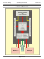
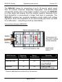
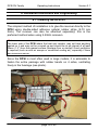
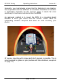
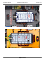
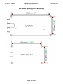
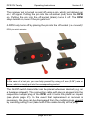
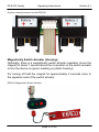
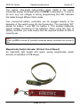
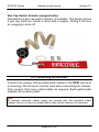
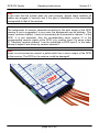
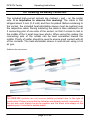
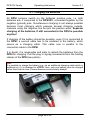
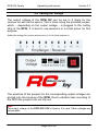
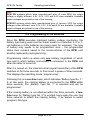
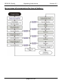
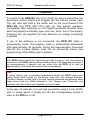
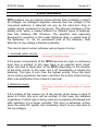
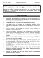
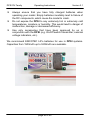
Operating Instructions DPSI RV Family Operating Instructions page 2 of 44 Version 2.1 DPSI RV Family Operating Instructions Version 2.1 Contents 1. Preface ............................................................................................. 4 2. Block Diagram DPSI........................................................................ 5 3. Features ........................................................................................... 6 4. The DPSI RV-Family in Headwords ............................................. 10 4.1. HFIB (High Frequency Interference Blocking) ....................... 11 4.2. APP (Advanced Push Pull Servo Pulse Amplification) .......... 12 4.3. IVM (Intelligent Voltage Monitoring)....................................... 12 4.4. Safety Features of the DPSI RV Systems ............................. 13 5. Packing Contents .......................................................................... 14 6. Installation Instructions and Programming................................ 15 6.1. Installing the DPSI RV ........................................................... 15 6.2. Hole spacing for Fastening .................................................... 18 6.3. Connecting the Switch Transmitter........................................ 19 6.4. Connecting the Receiver ....................................................... 23 6.5. Selecting the Batteries........................................................... 25 6.6. Soldering the Battery Connectors.......................................... 27 6.7. Charging the Batteries ........................................................... 28 6.8. Setting the Voltage ................................................................ 29 6.9. Programming of the Batteries ................................................ 30 6.10. Connecting the Servos ........................................................ 33 6.11. Connecting Additional Products........................................... 34 6.12. EMCOTEC Filter Capacitor ................................................. 35 7. Operation ....................................................................................... 36 8. Error Indications ........................................................................... 37 9. Safety Instructions........................................................................ 39 10. Technical Data of the DPSI RV / DPSI 2001 RV ........................ 41 11. Warranty....................................................................................... 43 page 3 of 44 DPSI RV Family Operating Instructions Version 2.1 1. Preface With the EMCOTEC DPSI RV (Dual Power Servo Interface – Regulated Voltage) you purchased a high grade, modern and secure product. We appreciate your trust and assure you that you made the right choice! Long lasting experience for years in development and manufacturing of electronically systems as well as the knowledge of the world’s best model airplane pilots has influenced the development of the DPSI systems. All products are manufactured at EMCOTEC GmbH in Germany on our own production line. Extensive optically and electronically end tests for every system, which leaves our house, assure that you, our customer acquire an absolute reliable product, which considerably increases the reliability of your valuable RC-Model. Of course, the products of the DPSI family not only have been tested extensively in the laboratory, but also went through intensive flighttesting. Extensive series of tests with especially in house developed data loggers have been accomplished to measure the real current consumption in model airplanes. Like done in the automotive industry an FMEA (Failure Mode and Effective Analysis) reduce the possibility of damage and malfunction on operating errors to a minimum. We kindly ask you to read these operating instructions carefully and to observe the installation hints. Thus, errors can be avoided in advance. We are all ears for your wishes and questions. Challenge us! Bobingen, March 2010 The Staff of EMCOTEC GmbH page 4 of 44 DPSI RV Family Operating Instructions 2. Block Diagram DPSI page 5 of 44 Version 2.1 DPSI RV Family Operating Instructions Version 2.1 3. Features A DPSI RV is used as a redundant power supply and current distributor for receivers and servos in RC-Models. The redundancy is accomplished by using two connected batteries. If one battery fails, the second battery guaranties safe operation. In the normal case, both batteries are discharged simultaneously. Furthermore, current is cut in half in each of “parallel” connected single battery. All servos directly connected to a DPSI RV are supplied with full power and each servo obtains maximum current without burden the damageable receiver. Due to switching the supply voltage electronically (the switch transmitter does not switch on the current but only supplies a switch-on signal), there is no power loss, weak contacts or transition resistance. For all DPSI RV systems, the electronically switches are built separately, i.e. the electronically parts are doubled. The switches are failsafe and are driven by self-holding circuitry, rather by a microcontroller. Thus, an operating DPSI RV stays powered on, even if the on/off switch transmitter is removed or broken or if the microcontroller is malfunctioning. Using DPSI RV systems, RC receiver sets reach new dimensions. In particular, a stabilized output voltage, which supplies the receiver as well as all servos, accounts for. A DPSI RV therefore offers: Battery switching function Complete voltage regulation for all RC components Electronically, failsafe switches Current distribution with HF filtering Battery voltage monitoring with acoustically warnings page 6 of 44 DPSI RV Family Operating Instructions Version 2.1 Voltage Regulation: Until now, the receiver set was supplied directly by the connected battery (or a corresponding battery switch). The output voltage depends heavily on the current discharge state. Because virtually always 2-cell LiPo batteries are being used in large model airplanes, a fully charged battery reaches up to 8.4 volts after the charger shuts off (depending on the charging current and the internal resistance). This peak voltage drops relatively fast, but can cause reduced lifetime of the servos in unfavorable cases, because the manufacturers usually allow only up to 6 volts. The electronics of the DPSI RV systems make sure, that the voltage of the batteries is reduced to an acceptable value, independent of the provided input voltage of the batteries. Using a jumper (a small connector), the output voltage can be adjusted in four steps (except for the DPSI 2001 RV – here the voltage is fixed). Thus, the power requirements can be adjusted to the pilots needs. In order to allow for servos with higher voltages, the output voltage of the DPSI RV Version 2010 can be adjusted in 4 steps up to 7.4 volts. Hint: In the DPSI RV system, receiver and servos are supplied with the same voltage which is generated from several voltage regulators. Low voltage warning: To inform the user about the discharging state of his batteries, a microcontroller using an intelligent algorism is integrated into the DPSI RV systems, to monitor all voltages. Errors (e.g. battery voltage too low) are unambiguously communicated through a built in buzzer acoustically and in the switch transmitter by the central LED optically. In order to allow for different battery types the DPSI RV can be set to the used battery. Switching to different battery types is easily done by simple programming. page 7 of 44 DPSI RV Family Operating Instructions Version 2.1 Hint: On delivery, the DPSI RV system’s low voltage recognition is programmed for 2cell LiPo batteries. For using other battery types, the corresponding type must be programmed first (see chapter 6.9)! The output voltage is set to 6.0 volts on delivery (DPSI 2001 RV 5.9 volts – other values on customer request possible). Different versions: The DPSI 2001 RV is the enhancement of the DPSI 2001 and supplies 26 servos altogether, which result from 10 receiver channels. Therefore, it is predestinated for all kinds of large model airplanes. Two additional outputs (MPX connectors) allow for connection of consumer loads, which can be supplied with unregulated battery voltage (e.g. 7.4 volts high load servos, smoke pumps, illumination etc.). Connection Schema DPSI 2001 RV: page 8 of 44 DPSI RV Family Operating Instructions Version 2.1 The DPSI RV allows for connecting of up to 32 servos, which result from 12 receiver channels. Especially large-glider- and airliner-pilots missed this variety. Due to the higher number of servos, the DPSI RV is a little larger and heavier then the smaller systems. Because more heat dissipation is encountered, a larger heat sink is necessary. The DPSI RV contains two complete separate current paths and voltage regulators. Even the breakdown of an electronically part does not lead to a malfunction – everything is built up redundantly. Connection Schema DPSI RV: DPSI Version ReceiverChannels ServoConnections Specialty DPSI 2001 RV 10 26* 2 high current outputs for unregulated battery voltage DPSI RV 12 32* output voltage selectable in 4 steps * Connect additional servos directly to the receiver page 9 of 44 DPSI RV Family Operating Instructions Version 2.1 4. The DPSI RV-Family in Headwords Dual power supply with regulated supply voltage for receiver and servos Output voltage adjustable in 4 steps from 5.4 volts to 7.4 volts (5.9 volts for DPSI 2001 RV) Compliant to all manufacturers RC receiver sets Continuously constant servo power through constant supply voltage LiIon / LeFePO4 / LiPo cells usable 5-, 6- (and 7-cell) NiCad / NiMH batteries usable Electronically, failsafe on/off switch transmitter with additional connectivity for external LED voltage displays Short-circuit-proof servo pulse amplification in current saving APP-Technology (Advanced Push Pull) HFIB (High Frequency Interference Blocking) blocking of HF interference caused by long servo cables (for each servo individually) Loadable up to 60 amps peak Up to 12 receiver channels including current distribution of up to 32 servos (depending on used system) IVM (Intelligent Voltage Monitoring) – intelligent voltage monitoring with acoustically and optically status indication for four different battery types (programmable) Reduced counter electro automotive force effect from servos through usage of plenty filter capacitors Cable free systems, i.e. all connections are pluggable and therefore replaceable anytime Problem free operation of two receivers possible Special grounding concept for undisturbed operation and most safety page 10 of 44 DPSI RV Family Operating Instructions Version 2.1 High grade plastic injection molding with integrated brackets for the battery connectors Large surface heat sink for deduction of lost heat Each system 100% tested and provided individual serial number Developed and manufactured by market leader (Made in Germany) DPSI Version DPSI 2001 RV DPSI RV Power Semiconductor 7 Max. Power Dissipation 15W * 10 15W * * Higher power dissipation (higher maximum current) possible when using active cooling (airflow) or larger heat sink (on request) 4.1. HFIB (High Frequency Interference Blocking) In order to increase safety, highly effective T-Filters are inserted in DPSI RV systems for every single servo (e.g. 32 pieces for DPSI RV). Although this is more expensive than simple filtering the receiver channels – disturbances are eliminated directly at the servo connector and therefore do not run through the whole printed circuit board. These filters reduce HF disturbances by up to 90% which can be “caught” by long servo cables. Radio interference suppression of the DPSI RV is considerable more effective than radio interference suppression by ferrite rings. Naturally, error free operation of digital servos is possible with all 2.4GHz receivers. page 11 of 44 DPSI RV Family Operating Instructions Version 2.1 4.2. APP (Advanced Push Pull Servo Pulse Amplification) Each servo is provided with optimally prepared amplified pulses from the receiver. Servo signals usually are weakened if servo cables are connected in parallel (V-cable), which makes them interference prone. The servo pulses stay fully maintained in DPSI RV systems, even if four servos are connected on one channel. Short circuit proof ness to the negative and positive lines is a specialty of the pulse amplification. If a mistake happens during wiring, which short cuts the pulse wire of a servo to negative or positive, the amplifiers are not destroyed and all other servos even on the same channel continue their operation problem free. An additional advantage is the current saving APPTechnology. The amplifiers are based on Push Pull output stages, which drive the low- as well as the high-phase of the servo pulse. Herewith, the high switching current is not applicable like in conventional open collector end stages, where the low phase of the servo pulse is generated via a resistor as a “short cut current”. Of course, the pulse amplifiers perfectly recognize and amplify weakest signal levels of some 2.4GHz receivers! 4.3. IVM (Intelligent Voltage Monitoring) An internal microcontroller monitors all voltages by using an intelligent algorithm and shows various faults (overload, low voltage, voltage faults) acoustically by means of a built-in piezo buzzer. Furthermore, errors are displayed through blink codes of the LED in the switch transmitter. page 12 of 44 DPSI RV Family Operating Instructions Version 2.1 4.4. Safety Features of the DPSI RV Systems Short circuits on the servo signal wires, regardless of whether they are toward the positive or negative wire of the servo cable, do not result in damage to the DPSI RV. All other servos of the channel in which the short circuit occurs remain fully functional. Even if the servo’s polarity is reversed, the DPSI RV is not damaged. A servo cable that is accidentally short-circuited will generally burn out or melt, without damaging the DPSI RV. The heat sink of the DPSI RV naturally becomes very hot when this type of short circuit occurs! The decoupling of the two batteries as well as the electronic switches is completely separate (including peripheral electronics) and therefore carried out twice. No double diodes are used (two diodes in one housing). Thus, the failure of one component can never lead to the failure of the entire system. The switching mechanism has already proven to be outstanding in several thousand systems. The DPSI RV does not need to be separated from the batteries during long breaks (e.g. in winter), since the self-discharging of the batteries is considerably greater than the quiescent current consumption of the DPSI RV, which is virtually immeasurable. To enable optical switch-on control, an ultra-bright light-emitting diode was installed into the switch transmitter of the DPSI RV. This signals that the system is turned on, even at great distances and indicates through blinking low voltage of the battery / batteries. All commercial remote control systems (Robbe/Futaba, Graupner, JR, Spektrum, Multiplex) were successfully tested in all types of modulation (PCM, SPCM, PCM1024, PPM, IPD, 2.4GHz etc.) in connection with the DPSI RV. Thus, all systems can be used trouble-free. page 13 of 44 DPSI RV Family Operating Instructions Version 2.1 The DPSI 2001 RV as well as the DPSI RV offers the option of connecting a second receiver. Both receivers should be of identical type (the type of modulation must always be the same). We recommend the DPSI TWIN for complete redundancy of the receiver set. Due to the elaborated safety properties in connection with extensive tests, operating errors and external influences usually do not lead to damage of the DPSI RV. 5. Packing Contents Shipment of DPSI 2001 RV: “DPSI 2001 RV“ base device with battery connector cables 10 pieces receiver connection cable (including servo connectors at both ends => patch cable) On/Off switch transmitter at one’s own option 4 pieces of high current connectors for the batteries and the DPSI 2001 RV (2 plugs and 2 sockets) 8 pieces shrink hose for the high current sockets Operating instructions EMCOTEC sticker Shipment of DPSI RV: “DPSI RV” base device 12 pieces receiver connection cable (including servo connectors at both ends => patch cable) On/Off switch transmitter at one’s own option 2 pieces high current sockets for the batteries 4 pieces shrink hose for the high current sockets Operating instructions EMCOTEC sticker Each DPSI RV system carries its own serial number and for each function, it is tested several times before delivery. page 14 of 44 DPSI RV Family Operating Instructions Version 2.1 6. Installation Instructions and Programming 6.1. Installing the DPSI RV The simplest method of installation is to glue the receiver directly to the DPSI using double-sided adhesive cellular rubber strips (5-10 mm thick). The receiver can also be attached separately; this is the preferred method when using 2.4GHz receivers. Hint: The lower side of the DPSI where the heat sink resides, may not have anything pasted on it and may not be covered up and should be at an interval of at least 30mm (1.2”) from the nearest surface (fuselage floor or similar)! Good ventilation is required (such as with air scoops or conducted cooling air), especially if there are numerous servos. Since the DPSI is most often used in large models, it is advisable to fasten the entire package with rubber bands on 4 sides, oscillating freely in the fuselage (see photo). page 15 of 44 DPSI RV Family Operating Instructions Version 2.1 Generally, you must always ensure that the fastening is as vibrationfree as possible and has sufficient air circulation. Reduction of vibration is particularly important for the receiver, since it reacts far more sensitively to mechanical vibrations than the DPSI. An approved method is to mount the DPSI to a mounting board between 4 short gas hoses and M4 screws. These serve as outstanding vibration dampers and allow for neat mounting (see photo). Of course, mounting with screws and short spacers is possible. This is recommended for gliders or jets (models with little vibrations, see photo on page 17). page 16 of 44 DPSI RV Family Operating Instructions page 17 of 44 Version 2.1 DPSI RV Family Operating Instructions 6.2. Hole spacing for Fastening page 18 of 44 Version 2.1 DPSI RV Family Operating Instructions Version 2.1 6.3. Connecting the Switch Transmitter With a mechanical switch, one risks a breakdown. There are intense vibrations at the sidewall of the fuselage. Thus, malfunctions of mechanical switches were observed many a time. In order to avoid mechanical influences, electronically switches including self-holding circuitries are used in DPSI systems. The electronically switches are only controlled by a pulse from the external switch actuator. Therefore the receiver set is turned on or off by a pin or magnet and the corresponding switch actuator only delivers the on / off signal. Switch Dimensions: Backside of the switch actuator including connected battery controllers page 19 of 44 DPSI RV Family Operating Instructions Version 2.1 The receiver set is turned on and off using a pin, which just delivers an on / off signal. Putting the pin into the on-socket (red) turns the DPSI on. Putting the pin into the off-socket (black) turns it off. The DPSI stays turned on, even if the pin gets lost. A DPSI only turns off by placing the pin into the off socket (i.e. moved)! DPSI pin switch actuator: Hint: In the case of a lost pin, you can help yourself by using a 2 mm (0.08”) wire or screw, which is simply put into the corresponding socket. The On/Off switch transmitter can be placed wherever desired (e.g. on a fuselage sidewall). The connection cable with plug is plugged into the respective multiple plug of the DPSI until it locks into place on impact (see photo page 21). In the event that replacement or removal is necessary, the plug can be disengaged from the multiple plugs upward by carefully pulling it out (take hold of the cable directly at the plug). page 20 of 44 DPSI RV Family Operating Instructions Version 2.1 A switch correctly mounted on the DPSI RV: Magnetically Switch Actuator (Housing): Optionally, there is a magnetically switch actuator available. Hover the magnet for about 1 second above the on-position of the switch actuator to turn the device on (green marking on plastic housing). For turning off hold the magnet for approximately 2 seconds close to the opposite mark of the switch actuator. DPSI RV Magnetically Switch Actuator: page 21 of 44 DPSI RV Family Operating Instructions Version 2.1 The central, ultra-bright light-emitting diode (LED) in the switch transmitter always illuminates when the DPSI is switched on. In case of an error (e.g. low voltage) or during programming the LED indicates the states through different blink codes. Two commercial battery controllers can be plugged directly to the backside of the switch using JR Uni-Connectors. The inscription “B1” stands for battery 1 and “B2” for battery 2. This enables additional optical voltage monitoring of the batteries. When using this type of battery controller, you must ensure that the required number of cells is correctly set. Hint: When the DPSI is turned off, possibly connected battery controllers are turned off also. Magnetically Switch Actuator (Printed Circuit Board): An especially light weight and space saving magnetically switch actuator is available in PCB design. page 22 of 44 DPSI RV Family Operating Instructions Version 2.1 Gas Cap Switch Actuator (magnetically): Alternatively a gas cap switch actuator is available. The design mimics a gas cap. Here too, switch is done with a magnet. Pulling it off turns on, plugging in turns off. 6.4. Connecting the Receiver Connect the receiver with provided patch-cables to the DPSI (see print on housing). Not all inputs must be used when connecting the receiver. Only connect that many patch-cables as required. Each patch-cable supplies the receiver power. Hint: All receiver connector cables supply the receiver with the regulated output voltage! Hence it is does not matter which cable (which channel) is connected. page 23 of 44 DPSI RV Family Operating Instructions Version 2.1 Hint: In the case that the system does not work properly, please check whether all cables are plugged in correctly and if the type of modulation of the transmitter corresponds to that of the receiver. Hint: The assignment of receiver channels according to the print image of the DPSI housing is just a suggestion! In any case, the assignment can be arbitrary. This means, receiver channel 1 must not necessarily be connected to channel 1 of the DPSI. It is just important, that the corresponding servo outputs fit to the corresponding receiver inputs at the DPSI (e.g. receiver input 2 to servo output 2). Therefore, receiver channel 1 can be connected to DPSI input 2. In this case, servos at output 2 are driven by receiver channel 1. Hint: Under no circumstances connect a patch-cable from a servo output of the DPSI to the receiver. The DPSI or the receiver could be damaged! page 24 of 44 DPSI RV Family Operating Instructions Version 2.1 6.5. Selecting the Batteries All commercially available batteries are considerable (NiCd and NiMH), as well as Lithium-Ion (LiIon) and Lithium-Polymer (LiPo) or LithiumFerrum-Phosphat (LiFePO4) batteries. These batteries are unlimited applicable independent of the selected output voltage. Even 6-cell (and 7-cell) NiMH batteries can be connected. This only makes sense if the output voltage of the DPSI is set to high values (7.4V) and the connected servos may be supplied with these higher voltages. Usually, 5-cell NiCd/NiMH or 2-cell LiPo batteries are utilized. Using 4-cell battery packs (NiCd / NiMH) are not allowed for a DPSI! Battery capacities Generally, ampacity and capacity of the batteries have to be considered. Thus, 2 battery packs with 450 mAh are much too small for a model with 10 servos. Here, two “2000’s” should be used, which can be discharged with 5C. (C is the nominal capacity in Ah => a battery of 2.0 Ah can be discharged at 5C with 5 * 2.0A = 10A). Especially when using digital servos anticipate higher current consumption. In addition, when selecting the batteries, you should ensure that the connection cables for the batteries are sufficiently thick. If a battery with a cable diameter of 0.25mm2 (AWG 24) is used, the advantage of the DPSI is partially negated, since losses will occur in the thin cable. Therefore, battery leads in larger models should be of the 1.0 – 1.5mm2 (AWG 15 - AWG18) type. The battery connection cables must be soldered to the delivered high current connectors (if no readily provided batteries are used), then they are compatible to a DPSI. A shrink hose for isolating soldering is provided, too. page 25 of 44 DPSI RV Family Operating Instructions Version 2.1 If for center of gravity purposes, the batteries are to be placed far away from the DPSI (i.e. long connection cables), it is advisable to twist the cables of the batteries. We recommend using our EMC Lithium Polymer batteries. These are supplied completely cabled and can be attached immediately to the DPSI. An additional charging connector at the battery enables charging without having to disconnect the battery from the DPSI. Charging devices for all battery types are also available from EMCOTEC. Selecting the output voltage Meanwhile, almost all servos and receiver are applicable for a supply of 5.9V. Therefore, the default setting for directly to a DPSI connected servos is 5.9V (DPSI 2001 RV) or 6,0V (DPSI RV). If 7.4V servos are to be used, the output voltage of the DPSI can be set to 7.4V by jumper. In case of using a LiPo battery the servos are supplied 7.4V. Hint: The higher the difference between the input- and output voltage, the higher the power dissipation converted to heat. If using many servos, it is advisable to select a higher output voltage at the DPSI. Recommendation for output voltages of DPSI RV: Application Recommended Output Voltage Tail rotor servos, helicopter with fast gyroscopes , servos for 4.8V according to manufacturer specifications Gliders, small motor models Aerobatic models, Jets, Airliners Combat models (Aerobatic) Servos working with 7.4V and 2.4GHz receiver (also supplied with 7.4V) 5.4V page 26 of 44 5.4V up to 6.0V 6.0V 6.0V up to 6.5V 7.4V DPSI RV Family Operating Instructions Version 2.1 6.6. Soldering the Battery Connectors The included high-current sockets are marked + and – on the solder side. It is imperative to observe this marking! The cable is first stripped about 5 mm (0.2 inch) and then tin-plated. Before soldering to the socket, the included heat-shrinkable sleeve must be pushed over the respective cable. During soldering the cable is then soldered to all 3 connecting pins of one side of the socket, so that it comes to rest in the middle of the 3 small legs (see photo). When using thin cables, the connecting pins of the socket can be bent somewhat toward the middle. Plenty of solder should be used to ensure good contact with all of the contacts. The heat-shrinkable sleeve is now shrunk using a hot air gun. Soldering the connectors: Hint: The DPSI RV systems are not reverse polarity protected due to the type of construction! Please ensure that the batteries are always correctly connected, i.e. the red wire must always be at the positive and the black wire always at the negative pole. It is better to double check! page 27 of 44 DPSI RV Family Operating Instructions Version 2.1 6.7. Charging the Batteries All DPSI systems switch on the batteries positive pole, i.e. both batteries are, if connected to the DPSI RV, connected together by the negative (ground) pole. Simultaneous charging is not always possible because most chargers which possess several charging outputs, measure using the negative line but join the positive wires. Separate charging of the batteries, if still connected to the DPSI is possible anytime! If charging of the battery should be possible, even if it is connected to the DPSI, a second cable has to be soldered to the battery, which serves as a charging cable. This cable runs in parallel to the connection cable to the DPSI. If in doubt, it is reasonable and safer to detach the batteries from the DPSI for charging. Pull the plug in zigzag movements from the holding clamps of the DPSI (see photo). Hint: It is possible to charge the battery (e.g. via an additional charging cable which is soldered on) if it is attached to a DPSI. Here, only one battery must be charged rather than both at once. Please observe correct polarity always! page 28 of 44 DPSI RV Family Operating Instructions Version 2.1 6.8. Setting the Voltage The output voltage of the DPSI RV can be set in 4 steps for the receiver as well as the servos. This is done using the provided jumper, which – depending on the output voltage - is plugged to the coding strip of the DPSI. It is best to use tweezers or a small pincer for this purpose. Setting the voltage for receiver and servos to 5.4 Volt (both jumpers in): The positions of the jumpers for the corresponding output voltages are printed onto the housing of the DPSI. Due to vibration less mounting of the DPSI the jumpers can not slip out. Hint: The output voltage of the DPSI 2001 RV is fixed to 5.9 volts. Other voltages are not possible. page 29 of 44 DPSI RV Family Operating Instructions Version 2.1 Hint: DPSI RV systems which were manufactured prior of June 2006 the output voltage is slightly different: 4.8V, 5.2V, 5.5V and 6.0V were available. Available output voltages are printed on top of the housing. DPSI RV systems which were manufactured prior of January 2010 the output voltages is also different: here 5.0V, 5.3V, 5.6V and 5.9V are available. Available output voltages are printed on top of the housing. 6.9. Programming of the Batteries Since the DPSI executes intelligent battery voltage monitoring, the battery type being used must be made known to it (whether 5, 6 or 7cell batteries or LiPo batteries are being used, for example). The type of battery only needs to be programmed once – the programmed status then remains saved in the microcontroller of the DPSI until possibly replaced by reprogramming. Programming starts up when only one battery (regardless of which type and to which battery connection) is connected to the DPSI and when the latter is turned on. After it is turned on, the internal buzzer (signal transmitter) of the DPSI switches on for three seconds, to then insert a pause of three seconds. This displays the operating mode “programming”. Following this is a one-time beep, which indicates “Battery type No. 1”. If, at this point, the missing battery is connected to the DPSI within three seconds, this „Battery Type No. 1“ is selected and will be programmed. If the missing battery is not attached within the three seconds, a twotime beep for “Battery type No. 2” is emitted. Here again the user has three seconds to attach the missing battery, if he wishes to select (program) this type. page 30 of 44 DPSI RV Family Operating Instructions Version 2.1 This principle is repeated until the buzzer has beeped five times (deactivate all tests). If the missing battery is not attached within three seconds, no programming is done and the system changes to the normal operating mode. The types of batteries are defined as follows: Buzzer code 1x beep 2x beep 3x beep 4x beep 5x beep Battery Type / Programming 5 cell battery (NiCad / NiMH) 6 cell battery (NiCad / NiMH) 7 cell battery (NiCad / NiMH) 2 cell LiPo battery Deactivate all tests At delivery, “Battery type No. 4” (LiPo battery) is programmed by default. When “5 beeps” is selected (all tests deactivated), the DPSI does not carry out any voltage tests. Therefore, no empty batteries or other faults are acoustically notified! Hint: Two identical batteries must be used at all times (i.e. the same battery type (NiCad, NiMH or LiPo) and same number of cells). The battery capacity may vary, on the other hand (even if this is not practical). Hint: If using LithiumIon batteries (LiIon) “battery type 2” is to select (6 NiCd/NiMH cells). This battery type corresponds to the discharge characteristic of LiIon batteries best. For LiFePO4 batteries “battery type 1” (5-cell NiCd) can be programmed. Better do not rely too much on low voltage warnings for LiFePO4 batteries because this battery type drops quickly at the end of its capacity. Here responsibility of the pilot is in order to judge the capacity (flight time) correctly. page 31 of 44 DPSI RV Family Operating Instructions An overview of programming the type of battery: page 32 of 44 Version 2.1 DPSI RV Family Operating Instructions Version 2.1 6.10. Connecting the Servos The DPSI 2001 RV distributes 10 receiver channels to a total of 26 servos (8 multiple V-cables “built in”). The DPSI RV distributes 12 receiver channels to a total of 32 servos (8 multiple V-cables “built in”). For this purpose, a distribution that enables a number of combinations has been selected. When using digital servos, mind good air ventilation for the heat sink. Hint: Depending on the number and power of servos being used the overall current consumption of the system changes. The higher the overall current, the more energy will be transformed into heat. The heat sink of the DPSI can therefore become very hot. This is not a fault, but rather represents normal functioning. Thus, sufficient heat dissipation must be provided for (clearance to neighboring walls, such as fuselage sidewalls or the like; cooling air supply, if possible). It is possible to install an additional heat sink. Hint: The assignment of the printed connections of the DPSI systems to the receiver is to be understood as suggestions! The receiver channels can be connected to arbitrary DPSI inputs. Thus, the receiver channel “1” can be put into DPSI input “3”. Servo outputs 3 of the DPSI are then being driven by receiver channel “1”. The assignment therefore is elective! page 33 of 44 DPSI RV Family Operating Instructions Version 2.1 6.11. Connecting Additional Products Operation of the DPSI RV with gyroscopes It is also possible to operate the DPSI using gyroscopes. In this case, you must ensure that the servo(s) is / are not attached to the gyroscope, but directly to the DPSI. The gyroscope is connected to the existing circuit directly between the DPSI and the receiver. Example: The gyroscope is to be connected to channels 2 and 5 of the receiver (for the ailerons). For this purpose, the gyroscope is connected as usual directly to the receiver (channels 2 and 5). The cables, that otherwise lead from the DPSI to the receiver, are now attached to the servo outputs (plugs) of the gyroscope. The servos are contacted to the DPSI following the usual procedure. Varios, smoke pumps, retractable gear and other consumer loads All other consumer loads can be connected directly to the DPSI like a normal servo. With the DPSI 2001 RV, additional consumer loads can also be contacted directly at the receiver if the slots (channels) in the DPSI 2001 RV are not sufficient. The DPSI 2001 RV allows for voltage outputs with unregulated battery power in order to connect additional consumers. This voltage is also switched by the electronically switches of the DPSI 2001 RV. Here, loads of up to 5A can be easily connected (additionally to “normal” loads) because there takes no power dissipation place. This is true for e.g. smoke pumps (APS PowerSmoke600). Servomatching (DPSI V-Match): If adjustments of individual servos are necessary (direction of rotation, center-point, end-position), the EMCOTEC DPSI V-Match is in order. Here, 2 servos can be connected; one of them can be adjusted as desired. Due to its high load capacity the DPSI V-Match can be directly connected to a servo output of a DPSI system. page 34 of 44 DPSI RV Family Operating Instructions Version 2.1 6.12. EMCOTEC Filter Capacitor Using powerful digital servos can cause these to induce extremely high peak voltages (counter electro automotive force) which, under certain circumstances damage the receiver or “crash” the microcontroller in the receiver. Because of their dimensions, filter capacitors built into the receivers often do not suffice to eliminate these disturbances. DPSI systems are equipped with up to 46 filter capacitors and additional parts to suppress or at least lower servo counter electro automotive force. Nevertheless, it is reasonable to additionally install the EMCOTEC filter capacitor (especially when using high power digital servos). The EMCOTEC filter capacitor is installed at an unused servo output (or at “Batt.”) directly at the receiver and makes sure, that peak voltages that can disturb the receiver are eliminated. Even short voltage dropouts will be effectively bypassed by this capacitor. In any case, the filter capacitor is a reasonable extension, which increases safety in the receiving system with or without a battery switch. page 35 of 44 DPSI RV Family Operating Instructions Version 2.1 7. Operation To switch on the DPSI RV, the 2 mm (0.08”) pin plug is pulled from the disconnect socket (black) and plugged into the turn-on socket (red). The red, ultra light LED in the switch and on the circuit board of the DPSI RV (not DPSI 2001 RV) light up. This signals operation. Immediately after switching on, the signal transmitter (buzzer) plays back the programmed battery type (one, two, three, four or five beeps). Following this, the algorithm for error detection (or voltage monitoring) is started. If one of the batteries is not connected, the DPSI RV starts in programming mode. This program mode is automatically abandoned after approximately 30 seconds. During this approximately 30-second interval, the missing battery must not be connected unless new programming of the battery type is desired. Hint: If the DPSI buzzer sounds for 3 seconds right after turning on, only one battery is connected to the DPSI and the device starts working in the programming mode. If no reprogramming is desired, one can either turn the DPSI off or wait for approximately 30 seconds and connect the second battery. Hint: A wrong battery type is probably programmed should the DPSI sound error codes shortly after turning on the device even with fully charged batteries. Possibly a battery is used, with a too high internal resistance and breaking down under heavy load (e.g. NiMH batteries in “AA” -Mignon size). Therefore, only batteries with high current load capability are to be used! In the case of a lost pin, you can help yourself by using a 2 mm (0.08”) wire or screw, which is simply put into the corresponding socket in order to the DPSI on or off. page 36 of 44 DPSI RV Family Operating Instructions Version 2.1 8. Error Indications DPSI systems use an internal microcontroller that constantly monitors all voltages. An intelligent algorithm ensures that low voltage of the connected batteries is detected not only by the short-term drop in voltage during movement of all servos. The internal resistance of the battery cells, which is indeed different for different types of batteries, thus has relatively little influence. The algorithm was especially designed for operation in RC model airplanes (thus a cyclical load of the batteries), i.e. not for permanent load of the batteries. Safe detection of low voltage is therefore possible. The internal piezo buzzer indicates various types of errors: 1. Overload (short circuit): ⎯⎯⎯⎯⎯⎯⎯⎯⎯⎯⎯⎯⎯⎯⎯⎯⎯ Error signal: Continuous beep If the power consumption of the DPSI becomes too high, a continuous buzz tone is emitted. In this case there is an external short circuit, which can lead to destruction of the DPSI (depending on the duration of the short circuit). In this case, turn it off immediately or remove the batteries. This type of error has the highest priority. Once the short circuit (during operation) has been corrected, the buzzer stops buzzing after a de-qualification time of about 4 seconds. 2. Batteries empty: ⎯ ⎯ ⎯ ⎯ ⎯ ⎯ ⎯ ⎯ ⎯ Error signal: continuous 0.1 second beep / 0.1 second pause If the voltage at the receiver (or at the servos) drops below a value of about 4.3 volts, this error will be emitted. In this case, the batteries (regardless of which type is being used) are completely discharged and safe operation is no longer possible. This error is extremely critical, since the entire RC system can completely “abort” at any time (due to the low voltage). page 37 of 44 DPSI RV Family Operating Instructions Version 2.1 Error type 2 has the second highest priority and remains active until the DPSI is turned off. When using LiPo cells, a condition is reached where the batteries can be irreparably destroyed if not turned off immediately and if the batteries are not immediately charged. 3. Low voltage in Battery 1: ⎯ ⎯ ⎯ ⎯⎯⎯⎯⎯⎯⎯⎯ Error signal: 3 x 0.1 second beeps, each with a 0.1 second pause, then a 1 second beep If the voltage of Battery 1 drops below a certain value, this buzzer code is emitted. The capacity of the battery is generally still sufficient for one flight before it needs to be recharged. Nevertheless, the battery should be recharged immediately after the error code sounds. It is always a prerequisite that the correct type of battery has been programmed (5, 6, 7 NiCad/NiMH cells or LiPo). This error code is repeated in 7-second intervals. Once the error has been qualified, it remains active until the DPSI is turned off. 4. Low voltage in Battery 2: ⎯ ⎯ ⎯ ⎯⎯⎯⎯⎯ ⎯⎯⎯⎯⎯ Error signal: 3 x 0.1 second beep with a 0.1 second pause each time, then 2 x 0.65 second beep with a 0.1 second pause If the voltage of Battery 2 drops below a certain value, this buzzer code is emitted. The capacity of the battery is generally still sufficient for one flight before it needs to be recharged. Nevertheless, the battery should be recharged immediately after the error code sounds. It is always a prerequisite that the correct type of battery has been programmed (5, 6, 7 NiCad/NiMH cells or LiPo). This error code is repeated in 7-second intervals. Once the error has been qualified, it remains active until the DPSI is turned off. If both Battery 1 and Battery 2 exhibit low voltage, both error codes will be emitted alternately. Error types 2 and 3 have lower priority than error code 1 (short circuit). Therefore, in case of a short circuit, error code emissions 2 or 3 will be interrupted. page 38 of 44 DPSI RV Family Operating Instructions Version 2.1 Hint: The limits for detecting low voltage of the algorism are designed especially for the operation of RC flight models. When the DPSI is used for other applications, it is possible that incorrect information may be given. If this is the case, the error message (if it is perceived as disturbing) can be completely hidden (see “Programming of batteries”). 9. Safety Instructions In general, all connecting lines should be run so that they do not come into contact with moving or hot parts of the model (such as servos, gears or sound absorbers). The DPSI must be protected from humidity and moisture. The DPSI must be located at a sufficient distance from neighboring surfaces to enable good heat dissipation of the heat sink. Improper handling of the DPSI can result in serious damage to property or injury of persons! Carry out a general inspection of all connections in your model before each use! All plugs must be correctly polarized and have clean contacts (i.e. fit tightly). Loose cables present a potential hazard! Under no circumstances may power sources being used that do not meet the specified voltages. The current-conducting contacts of the connector plugs may not be short-circuited. If you fail to observe this warning, the shortcircuited cables may overheat and even melt. The DPSI may not be taken apart or technically altered under any circumstances. Never use the DPSI for purposes other than for RC model building as a hobby. Above all, their use in passenger-carrying equipment is strictly prohibited. Operate the DPSI only with the remote control components provided for model making. page 39 of 44 DPSI RV Family Operating Instructions Version 2.1 Always ensure that you have fully charged batteries when operating your model. Empty batteries inevitably lead to failure of the RC components, which cause the model to crash. Do not expose the DPSI to any extremely hot or extremely cold temperatures, moisture or humidity. This would lead to danger of malfunction, damage or decreased efficiency. Use only accessories that have been approved by us in conjunction with the DPSI (e.g. On/Off switch transmitter, external voltage indicators, etc.). We recommend EMCOTEC LiPo batteries for use in DPSI systems. Capacities from 1500mAh up to 5300mAh are available. page 40 of 44 DPSI RV Family Operating Instructions Version 2.1 10. Technical Data of the DPSI RV / DPSI 2001 RV Power Sources 5, 6, 7-cell NiCad / NiMH cells, Lithium-Ion batteries, Lithium-Polymer batteries Operating Voltage Range 5.0V.... 10V Nominal Input Voltage 6.0V.... 8.4V Output Voltage 5.4V / 6.0V / 6.5V / 7.4V jumper selectable 5.9V for DPSI 2001 RV Quiescent current (when off) Approx. 1µA pro battery Quiescent current (when on) Approx. 90mA total Max. continuous current @ 5.9V (15 minutes with LiPo batteries) @7.4V Output Voltage 8A DPSI 2001 RV / 8A DPSI RV Max. peak current @5.9V 60A DPSI RV / 60A DPSI 2001 RV Drop-out losses @ 4A 0.3V DPSI 2001 RV 0.4V DPSI RV Maximum Power Dissipation (Continuously) 15W DPSI RV / 15W DPSI 2001 RV Number of servos in system Up to 26 Servos DPSI 2001 RV Up to 32 Servos DPSI RV CE Test Under terms of 2004/108/EC Environmental conditions -10°C .... +50°C (14°F … 122°F) Permissible temperature range -25°C .... +70°C (-13°F … 185°F) LCL filtering (EMI) For each individual servo output Interference signal suppression at 35 MHz -20dB @ 35MHz, -34dB @ 100MHz Dimensions including latches for connecting the battery 120mm x 75mm x 14,8 (18,5mm) DPSI 2001 RV (4.72“ x 2.95“ x 0.58“) 173mm x 85mm x 15,8mm DPSI RV (6.81“ x 3.35“ x 0.62“) Screw diameter for fastening 4 x 4,2mm (4 x 0.17 in) Hole spacing for fastening 109,0mm x 64,0mm (4.29“ x 2.52“) (DPSI 2001 RV) 152,3mm x 75,7mm (6,00“ x 2.98“) (DPSI RV) Weight: 170g (6 oz) 215g (7.58 oz) 15g (0.53 oz) Warranty DPSI 2001 RV DPSI RV Switch Actuator 2 x 10A (20A) DPSI RV 24 month page 41 of 44 DPSI RV Family Operating Instructions Version 2.1 Special features: Double power supply with controlled voltage for receivers AND servos Output voltage adjustable in 4 stages from 5.4 V to 7.4V (per jumper) Compliance with all manufacturer specifications for RC receiving equipment Continually constant servo-actuating power from constant power supply LiIon / LiFePO4 / LiPo batteries applicable 5.9V fixed voltage for DPSI 2001 RV (other values on customer request) 5-, 6- and 7-cell NiCd / NiMH batteries usable Electronically, fail-safe On/Off switch with additional connection option for external LED voltage displays Short circuit-proof servo pulse amplification in power-saving APP technology (Advanced Push Pull) HFIB (High Frequency Interference Blocking), blocking of injected high frequency interference from long servo-cables (separate for each servo) Capable of bearing up to 60 A peak current 10 receiver channels with current distribution to 26 servo outputs for DPSI 2001 RV 12 receiver channels with current distribution to 32 servo outputs for DPSI RV IVM (Intelligent Voltage Monitoring) – intelligent voltage monitoring with acoustic status indicator for four different types of batteries (programmable) Problem free operation of 2 receivers possible (for DPSI 2001 RV and DPSI RV) Special grounding concept for trouble-free operation and maximum safety High-quality housing of plastic injection molding with integrated holding clamps for the battery connector plugs for DPSI RV Large-surface cooling elements for deflecting heat loss Each system 100% inspected and provided with a unique serial number Developed and produced by the market leader (Made in Germany) Technical modifications and errors excepted! page 42 of 44 DPSI RV Family Operating Instructions Version 2.1 11. Warranty EMCOTEC GmbH shall issue a 24-month warranty on the DPSI RV. The guarantee period shall begin with delivery of the equipment by the retailer and shall be not extended by any guarantee repair or guarantee replacement. During the period of guarantee, the warranty shall cover the repair or replacement of any proven manufacturing or material defects at no charge. There shall be no specific entitlement to repair work. In case of a guarantee claim, the manufacturer shall reserve the right to exchange the equipment for a product of equal value if repair of the item is not feasible for economic reasons. There shall be no assumption of liability for consequential damages that are brought about by a proven defect during operation of the DPSI RV. There shall be no extended claims for damages. All transportation, packaging and travel expenses shall be borne by the purchaser. No liability shall be assumed for any damages during transport. If repair is needed, the equipment must be sent to the appropriate service center of the respective country or directly to EMCOTEC GmbH. The guarantee shall only be valid when the following conditions are met: The guarantee document (original invoice) must include the delivery date, the company stamp, the serial number and signature of the retailer. No intervention in the equipment may have been undertaken. It must have been operated in accordance with our operating instructions. Only the power sources and other accessory devices and components that were recommended by us may have been used. The guarantee document, the original invoice and other pertinent information regarding the malfunction (a short description of the defect) must be included with the transmittal. The equipment must still be the property of the initial purchaser. If equipment is sent in that later proves to be functional following an initial inspection, we shall impose a flat processing fee of € 15. In all other respects, the general business terms and conditions of EMCOTEC embedded controller technologies GmbH shall apply for any items not listed. page 43 of 44 DPSI RV Family Operating Instructions Version 2.1 Legal Information: Trademarks: The following names are registered trademarks: EMCOTEC DPSI DPSI RV Other product names mentioned in this manual may also be trademarks or registered trademarks of their respective owners. Copyright information: This manual is copyrighted by EMCOTEC GmbH. All rights reserved. This document may not be copied either entirely or in part, nor may it be transferred to any type of medium or translated into any other language without the express written approval of EMCOTEC GmbH. Manual Note: EMCOTEC GmbH reserves the right make changes to this manual and to equipment described herein without notice. Considerable effort has been made to ensure that this manual is free of errors and omissions. We shall not assume responsibility or liability for any errors that may be contained in this manual nor for any incidental, concrete or consequential damage that may arise from the provision of this manual, or the use of this manual in operating the equipment, or in connection with the performance of the equipment when so operated. page 44 of 44