1
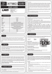
LED Edition
2.4G DSSS Technology
3-Channel 2.4G Radio Control System
INSTRUCTION MANUAL
• Before using, read this manual carefully
AUX Channel
Steering Trim
Steering Wheel
TRIM LED
Power Switch
Charging Jack
Bind Switch
Throttle Trim
St. Dual Rate
Throttle Trigger
Battery Box
CAUTION
• To use your Radio with your models correctly and safely, read this manual carefully and keep it in a
safe place for future reference.
Warning:
1. This product is only equipped for radio controlled cars;
2. The usage of this product should be approved by local law or regulations;
3. We will not be responsible for the damages caused by unauthorized modification, adjustment
or replacement of parts on this product;
4. The manual may be change without prior notice. Please contact us if you have any corrections
or clarifications that should be made in the manual;
• Before turning on the transmitter, make sure the transmitter batteries are fresh. The voltage of the
transmitter batteries is never lower than 9.6V, and please check and confirm that the servos are
all well and properly connected.
• Keep the radio system away from moist, high temperature and strong vibrations. Do not clean radio
with any solvent.
• Make sure antenna does not touch anything when power switch is turned on. Do not leave this radio
in reach of small children.
• Please use this product according to your local laws and regulations, we are not responsible for any
incidents or damages.
Steering Dual Rates Setup
ST.TRIM
INC
ST.DR
TH.TRIM
LEFT
DEC
RIGHT
MID
NOR
REV
POWER ST.DR
ST.
ST.D/R SW
TH.
•DEFINITION:
Steering Dual Rate (ST. DR): Is the adjustment that allows the dual rate value (maximum
servo travel) to be increased (INC) or decreased(DEC) with in a range of 0% to 100%
of the steering servo. This functions very useful in a race conditions as it allows you to
tailor the steering radius and sensitivity for the current track conditions.
•ADJUSTMENT:
1.Press and hold the “INC” (Increase) button until the LED on the “ST.DR” turn solid
indicating the maximum turning radius or value of 100%.
2.Press and hold the “DEC” (Decrease) button until the LED on the ‘ST.DR” goes dim or out
to reach the minimum turning radius or value 0%.
CHECKING YOUR DUAL RATE
•To Check Your Dual Rate: First turn your radio “ON” then turn “ON” your
vehicle. Check your steering on your radio by turning left and right several
times. Now turn your steering wheel all the way to the left or right whichever
you choose and hold it their while pushing the “DEC” (decrease) button on
the “ST-DR” and hold it down, you should see that the wheel on your vehicle
decrease in radius and that the LED on “ST-DR” will start blinking and slowly
dim. Now to increase the dual rate turn the wheel left or right all the way and
hold it while pushing the “INC” button this will increase the radius of the wheel
and the LED on ST-DR will start blinking slowly and turning solid indicating
that the “Dual Rate” is at 100% . When running your vehicle try to run the
“Dual Rate” at maximum radius (100%). Then if you have too much steering
then decease as needed.
0%
0%
0%
10
10
0%
POWER ST.DR
INC
ST.D/R
DEC
0%
100
%
10
0%
100
%
10
0%
2.4Ghz Binding
•Press and hold the bind button on the front of the transmitter while
turning ON the power switch button until the (ST.DR) LED Flashes.
2. With the system hooked up as shown, insert the binding cable in
the charging plug receptacle. Turn on the power of the receiver
(4.8 - 5.6V), and now the LED should be flashing indicating
that the receiver is ready to bind.
Flashing LED
Plug In
Binding cable
STEP 2 Power Switch (turn on)
Receiver
3. The LED should go solid, indicating the system
has connected. Now turn off the receiver and
remove the binding cable.
Solid LED
STEP 1 Bind (Press and hold)
Binding cable
Receiver
AUX Channel Function (CH3)
•This switch control the transmitter’s third channel. A servo plugged in this Channel 3 will move to full travel in one direction when
the switch is in the “AUX” position, then move the switch to the “OFF” position the servo will move in the opposite position . This
channel can be use to turn on all sort of things in your vehicle. For example, lights, on board camera etc..... l
Handling Procedure For Batteries
NOTICE THE DIRECTION OF BATTERY COVER
•Battery Replacement
1) Remove the battery cover from the transmitter by sliding it in the direction of the arrow.
2) Remove the used batteries.
3) Load the new 8 AA size alkaline, or Nickel Metal Hydride (NimH) rechargeable batteries,
and pay very close attention to the polarity marking on the batteries.
4) Slide the battery cover back onto the case.
5) If you use rechargeable batteries OFNA make this charger 10210 it will charge your Transmitter
9.6v at 100mA and Receiver battery 4.8v-6v at 100mA at the same time.
•Caution
Always make sure you reinsert the batteries are in the correct polarity order. If the batteries are loaded
incorrectly, the transmitter may not work or can be damaged.
When the transmitter is not used for a long period of time remember to remove the batteries. If the batteries
do happen to leak, clean the batteries case and contacts thoroughly and make sure the contacts are free of
corrosion.
•Battery Disposal
Some countries and state require special handling of used batteries, please contact the agencies responsible
for recycling hazardous wastes in your local area.
•Battery low voltage alarm indicator. LED Power light will flash.
Receiver Connection Diagram
10210 - DUAL CHARGER, 4.8V-6V/9.6V TRANSMITTER AND RECEIVER
(Not included)
Specification Data
•Transmitter
•Receiver
Channels: 3
Frequency: 2.4Ghz
Power DC: 9.6V - 12V
Measurement: 280 x 190 x 85mm
(Packing Meas.)
Net Weight: 510g
Channels: 3
Frequency: 2.4Ghz
Power DC: 4.8 - 5.6V
Net Weight: 13.5g
B4218 ESC Instruction and Specification
WARNING ELECTRIC MOTOR AND ESC ARE EXTREMELY HOT AFTER
RUNNING, CAN CAUSE SERIOUS INJURY, HANDLE WITH CARE
•Special Features:
1. Exclusive feature for this model. Auto set to neutral position on the throttle. No programming
or adjustment is required. Just one second after powering on the system, the speed control
will beep indicating that is has auto set to the neutral position ( while the speed control is
setting the neutral position do not touch the throttle trigger, leave it at neutral ).
Fig.1
FORWARD
Fig.3
Fig.2
BRAKE
AND
REVERSE
NEUTRAL
2. Thermal Protection Function of The ESC B4218. If the speed control over heats, the Thermal
Protection function will be activated. Once the “TP” is activated, the throttle will rapidly turn
on and off and acceleration becomes erratic. Stop driving immediately, do not drive the car
until the Speed Controller cools down.
3. LED indication, two colors Green/Red
4. Large sturdy aluminum heatsink for maximum heat dispersing.
CAUTION
•THIS ESC DO NOT HAVE “LVC” (Low Voltage Cutoff): What this means is this ESC or
speed control do not have the circuitry to detect the low voltage of the Lipo or
Lithium Polymer battery to prevent the battery from discharging too low during
use, which would make the pack unusable and unstable. The cutoff is usually
around 6.25 volts or 3.0 volts per cell. Once a Lipo discharges below 3.0 volts per
cell, there is a chance that the battery will catch on fire. Use Lipo batteries at your
own discretion OFNA is not responsible for misused and damage to personal
property and injuries.
TH.TRIM
•Specification:
1. Input Voltage: 6~8.4V 6-7cell NiMh or NiCd
2. Power IC 150A at (77F), 100A at (212F)
3. Supported motor >12T - 27T Mabuchi Motor
4. Factory default Spec: Output Continuous/Peak Current 70A/120A(10sec)
5. Over temperature protection at 200F.
6. BEC Voltage 5V at 1Amp
7. FET internal: forward/reverse...........0.0025/0.005 ohm
8. Size:36 x 35 x 30.5mm
9. Weight......53.7g/1.89oz
FIG. 4
BLUE NEG
BATTERY
ORG. POS.
SWITCH
RECEIVER WIRE
•Throttle Neutral and ESC setting:
FIG. 5
1. Switch on the transmitter.
2. Set the throttle trim to the middle or the green LED on your Transmitter “TH”
3. Switch on the power of the ESC
4. The ESC will sound 3 beeps (DO RE MI) confirmation, indicating the ESC
is ready & the throttle is at neutral position.
•Operating Instructions:
1. Connect the ESC wires to the motor. (Blue is neg and Orange is Positive See Fig. 5)
2. Plug the receiver wire into the throttle or #2 channel on the receiver
3. Ventilation - Mount the ESC in a location that has good ventilation & isolate it from vibration
and shock. Ventilation is extremely important for cooling the ESC & Motor.
4. Plug in your battery, before turning on the ESC, make sure your transmitter is on & the throttle
trigger is at the neutral position. (See Fig 2)
5. Turn on your ESC, the LED light on the ESC will flash red then goes to solid green and a tone
will sound indicating that the ESC is set and ready to go.
FOR ADDITIONAL HELP YOU CAN CALL OFNA TECH SUPPORT AT (949)586-2910 OR
GO TO WWW.OFNA.COM/GUIDE.HTML FOR HOW TO VIDEO
Warranty Period
OFNA warranties that the Products purchased (the “Products”) will be free from defects in materials and workmanship at the
date of purchase by the Purchaser.
Limited Warranty
(1) This warranty is limited to the original Purchaser (”Purchaser”) and is not transferable. REPAIR OR REPLACEMENT AS
PROVIDED UNDER THIS WARRANTY IS THE EXCLUSIVE REMEDY OF THE PURCHASER. This warranty covers
only those Products purchased from and authorized OFNA dealer. Third party transactions are not covered by this
warranty. Proof of purchase is required for warranty claims. Further, OFNA reserves the right to change or modify this
warranty without notice and disclaims all other warranties, express or implied.
(2) Limitations - OFNA MAKES NO WARRANTY OR REPRESENTATION, EXPRESS OR IMPLIED, ABOUT NONINFRINGEMENT, MERCHANTABILITY OR FITNESS FOR A PARTICULAR PURPOSE OF THE PRODUCT. THE
PURCHASER ACKNOWLEDGES THAT THEY ALONE HAVE DETERMINED THAT THE PRODUCT WILL SUITABLY
MEET THE REQUIREMENTS OF THE PURCHASER’S INTENDED USE.
(3) Purchaser Remedy - OFNA sole obligation hereunder shall be that OFNA will, at its option, (1) repair or (2) replace, any
Product determined by OFNA to be defective. In the event of a defect, these are the Purchaser’s exclusive remedies.
OFNA reserves the right to inspect any and all equipment involved in a warranty claim. Repair or replacement decisions
are at the sole discretion of OFNA. This warranty does not cover cosmetic damage or damage due to acts of God,
accident, misuse, abuse, negligence, commercial use, or modification of or to any part of the Product. This warranty does
not cover damage due to improper installation, operation, maintenance, or attempted repair by anyone other than OFNA.
Return of any goods by Purchaser must be approved by OFNA before shipment.
Damage Limits
OFNA SHALL NOT BE LIABLE FOR SPECIAL, INDIRECT OR CONSEQUENTIAL DAMAGES, LOSS OF PROFITS OR
PRODUCTION OR COMMERCIAL LOSS IN ANY WAY CONNECTED WITH THE PRODUCT, WHETHER SUCH CLAIM
IS BASED IN CONTRACT, WARRANTY, NEGLIGENCE, OR STRICT LIABILITY. Further, in an event shall the liability of
OFNA exceed the individual price of the Product on which liability is asserted. As OFNA has no control over use, setup, final
assembly, modification or misuse, no liability shall be assumed nor accepted for any resulting damage or injury. By the act
of use, setup or assembly, the user accepts all resulting liability.
If you as the Purchaser or user are not prepared to accept the liability associated with the use of this Product, you are advised
to return this Product immediately in new and unused condition to the place of purchase.
Safety Precautions
This is a sophisticated hobby Product and not a toy, It must be operated with caution and common sense and requires some
basic mechanical ability. Failure to operate this Product in a safe and responsible manner could result in injury of damage to
the Product or other property. This Product is not intended for use by children without direct adult supervision. The Product
manual contains instructions for safety, operation and maintenance. It is essential to read and follow all the instructions and
warnings in the manual, prior to assembly, setup or use, in order to operate correctly and avoid damage or injury.
FOR ADDITIONAL HELP YOU CAN CALL OFNA TECH SUPPORT AT (949)586-2910 OR
GO TO WWW.OFNA.COM/GUIDE.HTML FOR HOW TO VIDEO
TO: OFNA TECHNICAL SUPPORT
7 VANDERBILT, IRVINE, CA 92618
TODAY’S DATE: month________day______
1. Print out form.
2. Fill out the form completely.
3. Make a copy of purchase receipt. All replacements/repairs will not be processed,
unless accompanied by proof that item(s) was purchased.
4. Call OFNA technical support at (949)586-2910 for assistance.
1. Your name
____________________________
2. Your address:
____________________________
____________________________
3. Your Phone Number
(_____)______________________
4. Your e-mail address:
____________________________
5. Summary of your problem (check lines):
a______part(s) is missing from my kit
b______part(s) seems to be defective
c______other problem
6. Name of kit / part (on tag or end of box)
_____________________________
7. Kit/part number (on tag or end of box)
_____________________________
8. Purchased from (store name)
_____________________________
a. Store phone: (_____) _________
b. _____Item was a gift?
9. If a part is missing form the kit, circle
the appropriate answers:
a. Yes / No: Is kit box damaged?
b. Yes / No: Factory Seal sticker was secure.
c. Yes / No: I am the original owner.
d. Yes / No: I have contacted the dealer first.
10. Describe your issue fully and include any part numbers:
____________________________________________________________
____________________________________________________________
____________________________________________________________
____________________________________________________________
____________________________________________________________
Failure to fill out this form completely will cause a delay in processing!
11. Affix proof of purchase on second page. All replacement / repairs will not be processed
unless accompanied by proof that item(s) was purchased.
Can’t find Proof of Purchase?
A. If you lost the store receipt, ask the store if they will give you a new one.
B. We do not accepted the following as a substitute: Hand written receipts, ebay transaction numbers/forms or
credit card statements.
12. Send in form with your defective product, as instructed to do by the Ofna
technician,(Name)_________________ you spoke to. Ph:(949)586-2910 Fax: (949)583-9272
53353
53060
53360
53351
53355
53366
53354
53368
53324
53352
53321
53356
53357
53309
53058
53373
53358
53372
53361
53369
53362
53371
53375
53370
53316
53324
53364
53315
53365
53363
53367
53374
53012
OFNA
53012
53024
53058
53060
53309
53312
53315
53316
53318
53321
53324
53351
53352
53353
53354
53355
53356
53357
53121 HYPER 18 SG W/PULLSTART
DESCRIPTIONS
BEARING,FRONT 7x19x6mm
HEX AXLE, PULL START, HYPER
BARREL STOP SCREW, HYPER
MAIN NEEDLE AND SEAL, HYPER
CLIPS, G, 5PCS
CAP SCREW 3x16mm (4PCS)
REAR COVER PULLSTART & O-RING
CAP SCREW 3x10mm (4PCS)
SILICONE MANIFOLD SEAL
THROTTLE RUBBER COVER
SUPPLY FUEL NOZZLE & O-RING
HEAD, HYPER 18 ENGINE
HEAD BUTTON HYPER 18
HEAD CAP SCREWS 3x12mm H18
HEAD BUTTON STANDARD HYPER 18
HEAD BUTTON TURBO HYPER 18
PISTON & SLEEVE HYPER 18
WRIST PIN & G CLIPS HYPER 18
RETAIL
6.95
10.95
4.95
5.95
1.95
1.95
13.95
1.95
3.95
3.45
5.95
34.95
2.95
2.95
22.95
24.95
82.95
5.95
OFNA
53358
53359
53360
53361
53362
53363
53364
53365
53366
53367
53368
53369
53370
53371
53372
53373
53374
53375
DESCRIPTIONS
CONNECTING ROD HYPER 18
SCREWS SET HYPER 18
PISTON, SLEEVE, ROD COMBO H18
BACK COVER & O-RING HYPER 18
O-RING COMPLETE SET HYPER 18
BALL BEARING,12x21x5mm H18
CRANKSHAFT HYPER 10
CRANKCASE W/FR&RR BEARING H18
MAIN NEEDLE HOUSING SET H18
TURBO FAN & ONE WAY HYPER 18
CARB. RESTRICTOR HYPER 18
CARBURETOR COMPLETE HYPER 18
CARB LOCKING PIN HYPER 18
THROTTLE BALL STUD HYPER 18
LOW END NEEDLE HYPER 18
CARB BODY AND THROTTLE H18
CAP SCREWS 2.6x7mm FOR PS H18
PULLSTART COMPLETE HYPER 18
OFNA
RETAIL
27.95
9.95
109.95
13.95
7.95
23.95
39.95
75.95
14.95
29.95
5.95
69.95
9.95
6.95
7.95
34.95
2.95
39.95
7 VANDERBILT
IRVINE, CA 92618
PHONE: (949) 586-2910
WWW.OFNA.COM
WWW.RCDEAL.COM
HYPER 18 ENGINE
PART # 53121
Thank you for purchasing a OFNA engine. We appreciate your choice and know you will enjoy running it. Please
note that the OFNA information in engine box is subject to change without notice.
NEW ENGINE BREAK-IN
Your OFNA engine is extremely tight when the piston is at the top of the stroke and turning the crankshaft by hand.
This is normal for a new ABC type engine. The piston and sleeve are matched for fit and the top of the sleeve is
tapered for a tight fit. As you run your engine, this tightness Should diminish. There is no cause for alarm, because
as the engine warms up, the brass sleeve will expand faster than the aluminum piston and the engine will turn free.
As with any new engine, there are many high spots and tight fits in the matching process. High spots create hot
spots that must be broke-in. Therefore, the break-in process is very important to provide good service by the
engine. So, you must run the engine rich (COOL) for the first two tanks of fuel. We recommend using 20% O’Donnell
0R BYRON’S 2000 as break-in fuel. Other break-in type fuels or added oil is NOT needed. DO NOT OVER REV. THE
THE ENGINE WHEN FIRST STARTING, this could break the rod, piston and over heat the sleeve. Let the engine run at
low RPM for one tank to break-in connecting rod bearing before starting full break-in.
Break-in the engine in the car, by running the engine at a rich setting. Factory high end or master needle is 4 turn
Out from all the way close. Run the car from a slow to fast speed with short bursts of speed. You need to build
Little heat in the engine, but not too hot. In a rich setting, the engine will run cool. In the leaner setting the engine run
Hot running hot is NOT good yet. Do not heat up the engine too much at this time. After about two (2) tank,
turn the Master Needle Valve, clock wise, 1/8 of a turn leaner or clockwise. Keeping the fuel tank full, continue the
process until you slowly turn the Master Needle Valve, 1/8 of turn each time, to a leaner point and in which the
engine runs at high RPM and power and the master needle should be at 3-3.5 turn out from close, but still keeping
The MAX TEMP UNDER 250 DEGREES F.
If you go over 250 degrees it is too lean of a setting and will over heat the engine and damage the piston.
Normal operating temperature is around 220 to 250 Deg. Temperatures of 260 Deg. and above will damage
Engine an shorten the life of the motor.
NEEDLE SETTINGS After break-in:
Master Needle Valve - (High End) Set at 3 to 31/2 turns from closed. Adjust this needle for
maximum RPM and power without being too lean or too hot. Make sure you start at bottom of needle seat!!
Mid Range needle - The brass needle on the side of the carb. DO NOT TOUCH.
Side Carb. Needle (Low Speed) - This needle is in the center side of the carburetor where the blue boot is, provide
Throttle response. It is not the idle adjustment. Set NEEDLE flush with the ball end. Turning in is Lean and Out is Rich.
Do not adjust This needle until the Master Needle is set for power and top speed. This will only effect throttle response.
Barrel Stop Screws - Used for adjusting Idle: Set for 1/16th inch gap to start new engines. You can open more for
faster idle.
OFNA/PICCO GLOW PLUG IS RECOMMENDED
51010
51011
51012
51013
51014
51015
-
B4 STANDARD HOT
B5 STANDARD MEDIUM
B6 STANDARD COLD
T4 TURBO HOT
T5 TURBO MED
T6 TURBO COLD
OFNA RACING , 7 VANDERBILT, IRVINE, CA. 92618 • TEL:(949)586-2910
11066
21006
21003
11066
21003
21003
21004
21003
21003
21004
11066
21004
21003
21001
94046
1000wt Silicone
11066
11066
21003
21038
21003
21003
21004
21003
21003
21004
11066
21003
21037 Steel for Nitro
21317 Delrin for Electric
94046
5000wt Silicone
94034
21005
21005
11065
21002
21002
21007
21007
11065
21015
21014
94002
21014 x 4
22012
21015
36870
21016
36870
21012
11066
11066
21017
18075
21017
18075
21017
94043
21028
21029
21028
21029
21009
94043
21009
21029
21123
94004
21029
21029
21123
94004
21008
94005
21008
94005
21030
21018 x 4
21018
21018
94005
21018
94033
94034
94049
21018
21019
21028
21029
21011
21029
21028
3.2mm
94041
21033
21078
21033
94041
21078
21078
21034
21033
21033
21033
21033
21078
21033
94033
21033
21033
21033
21013
94002
21036
21036
21023
21023
94002
21019
94004
94003
21058
21026
11066
21025
21017
11066
18075
18075
21017
36870
94041
21027
21059
21059
21123
94004
21029
21123
21028
21029
21024
21028
21029
21029
94043
21021
21021
94043
21030
19031
94038
94003
19031
21020
94004
94041
21022
21035
21035
94005
21022
21018
21018
21018
94005
21018
94033
94034
21018
21031
94021
21031
21031
94020
21031
21031
94002
94005
94033
21032
90020
21058
21032
21032
21244
94020
21019
21241
94019
21039 x 2
19052
21077
19052
21077
21039
21040
21041
21042
21041
21039
21041
21041
94002
21042
94033
21242
94019
21242
21242
21242
94038
10097
28061
28061
10097
21054
21054
21041
10010
10010
10101
10101
94056
10410
10410
10410
18077
10410
21055
94017
94018
21054
21055
21243
21044
94019
10067
10067
10181
10181
94034
94026
19082
10177
94033
21050
94041
21050
21050
21050
21049
94002
94022
21050
21050
21049
94002
21049
21049
21047
21049
21049
10282
21046
21046
94001
21046
21046
21046
28061
28081
94017
21053
21053
21052
29056
21052
21036
21035
21036
21035
21067
21228
21064
21228
21062
21228
21228
22012
90020
21067
21228
21062
21067
21065
21228
21228
21228
22012
90020
21067
21063
21067
21064 Cap/Shock Body Front
21065 Cap/Shock Body Rear
21066
19018
21067
21068
21068
19031
94005
94038
94005
21245
21246
10993
10993
10993
10993
21071
21071
21248 Clear
21249 Blue
21250 White
22086
FOLLOW STEPS A TO H FOR ELECTRIC VERSION TO INSTALL CENTER DIFF AND MOTOR MOUNT.
A
21242
94017
21039
21242
21241
94019
21301
94017
94019
21315
B
21308
21308
21254
94056
Doublesided Tape
94034
94056
C
94005
94005
21302
D
Battery not included
21307
21304
E
21304
94019
94019
F
21303
94017
94002
21049
94002
94017
94017
G
29076
29076
29076
21035
H
21036
Factory setup
21001
21011
21021
21031
21041
29056
21002
21012
21022
21032
21042
21052
21003
21013
21023
21033
21241
21053
21004
21014
21024
21034
21044
21054
21005
21015
21025
21035
21243
21055
21006
21016
21026
21036
21046
22084
21007
21017
21027
21037
21047
22071
21008
21018
21028
21038
10181
21058
21002
21019
21029
21039
21002
21020
21030
21040
21049
21050
21059
21242
21244
21070
22012
21071
10101
21253
21281
21228
18075
21248
21062
21249
22075
18077
11064
21063
22086
28061
28081
28087
21064
21246
10097
10282
21251
21065
21245
11065
10993
21252
21066
19082
11066
21067
21077
22087
19018
21068
21078
10010
19031
21069
21079
29073
10177
OFNA
10010
10097
10101
10177
10181
10282
10985
11064
11065
11066
18075
18077
19018
19031
19082
21001
21002
21003
21004
21005
21006
21007
21008
21009
21011
21012
21013
21014
21015
21016
21017
21018
21019
21020
21021
21022
21023
21024
21025
21026
21027
21028
21029
21030
21031
21033
21034
21035
21036
21037
21038
21039
21040
21041
21042
21044
21046
21047
21050
21051
21052
21053
DESCRIPTIONS
HYPER TT PARTS LISTS
CLUTCH SHOES, BLACK, 3 SHOES
CLUTCH NUT SG HYPER
SPRINGS,CLUTCH,GOLD 1.1M 3PCS
FUEL LINE 2FT. GRAY/BLACK
JOINT, EXHAUST TUBES, 2PC
SWITCH COVER, SILICONE BLACK
NYLOK FLANGE NUT,4mm BLUE 10P
BEARING 5x8, 4PCS.
BEARING 5x11, 6PCS. SC 10
BEARING 10x15, 4PCS.SC 10
BEARING, 6x13mm. 4PCS.SC 10
BEARING, 5x10mm, 4PCS.
BOOT,SHOCK SHAFT,SILICONE 4PCS
BALL,STEEL,SHOCKS 4PCS.
MOUNT, PIPE WIRE
GEAR, CROWN HYPER 10SC
GEAR, PINION HYPER 10SC
GEAR, DIFF HYPER 10SC
DIFF CASE W/GASKET HYPER 10SC
DRIVE CUP CENTER HYPER 10SC
DRIVE CUP F/R DIFF HYPER 10SC
GEARBOX CASE HYPER 10SC
SHOCK MOUNT FR HYPER MINI
FRONT HINGE PIN HOLDER FR 10SC
ARM, UPPER FRONT HYPER 10SC
ARM, LOWER FRONT HYPER 10SC
TOP PLATE FRONT HYPER MINI
STEERING KNUCKLES FRONT H.10SC
PILLOW BALL HYPER 10SC
CVA, FRONT HYPER 10SC
HEX HUB HYPER 10SC
ANTI ROLL BAR SET HYPER 10SC
BUMPER SET F/R HYPER MINI
SHOCK TOWER REAR HYPER MINI
HINGE PIN HOLDER REAR H.10SC
ARM, UPPER REAR HYPER 10SC
TURNBUCKLE, STEERING H. 10SC
ARM, LOWER REAR HYPER 10SC
UP-RIGHT REAR HYPER 10SC
AXLES REAR HYPER 10SC
DOGBONES REAR HYPER 10SC
HINGE PIN SET HYPER 10SC
HINGE PIN BUSHING HYPER 10SC
BODY POST FRONT HYPER MINI
WING MOUNT HYPER MINI
SERVO SAVER SET HYPER 10SC
SERVO SAVER ARM HYPER 10SC
TURNBUCKLE REAR UPPER ARM 10SC
TURNBUCKLE ENDS HYPER 10SC
SPUR GEAR STEEL HYPER 10SC
CENTER DIFF OUTPUT HYPER 10SC
CENTER DIFF MOUNT HYPER 10SC
BRAKE DISC HYPER MINI
BRAKE CAM SET HYPER MINI
CENTER TOP DIFF PLATE H. MINI
FUEL TANK POST & LID PLR H.M.
RECEIVER BOX HYPER MINI
RADIO TRAY ALUM. HYPER MINI
THROTTLE LINKAGE SET H.M.
AIR FILTER TUBE HYPER MINI
AIR FILTER SET HYPER MINI
AIR FILTER FOAM REFILL H.M.
RETAIL OFNA
13.95
5.95
4.95
1.95
6.95
3.95
8.95
11.95
17.95
15.95
15.95
15.95
8.95
7.95
5.95
24.95
12.95
12.95
6.95
11.95
12.95
8.95
6.95
5.95
6.95
9.95
5.95
10.95
16.95
34.95
6.95
9.95
9.95
7.95
5.95
6.95
10.95
10.95
7.95
12.95
12.95
11.95
4.95
6.95
11.95
19.95
6.95
10.95
5.95
24.95
14.95
10.95
7.95
12.95
5.95
3.95
12.95
10.95
10.95
6.95
8.95
10.95
21054
21055
21058
21059
21062
21063
21064
21065
21066
21067
21068
21069
21070
21077
21078
21079
21123
21141
21159
21162
21163
21164
21241
21242
21243
21244
21245
21246
21247
21248
21281
21308
22012
22017
22028
22071
22075
22084
22086
22087
28061
28087
29073
21251
21252
21253
21254
21159
21301
21302
21303
21304
21307
21311
21312
21313
21314
21315
21316
21317
DESCRIPTIONS
ENGINE MOUNT HYPER MINI
CLUTCHBELL 14T STOCK HYPER M.
BRACE, CHASSIS FR/RR H. MINI
HINGE PIN REAR 3x35mm H. 10SC
SHOCK SHAFTS FR/RR HYPER MINI
SHOCK BLADDER HYPER 10SC
SHOCK BODY FRONT HYPER MINI
SHOCK BODY REAR HYPER MINI
SHOCK COLLAR THREADED H.10SC
SHOCK PLASTIC PARTS HYPER 10SC
SHOCK SPRINGS SET FR/RR H.MINI
SHOCK, FRONT SET HYPER MINI
SHOCK, REAR SET HYPER MINI
BRAKE PADS
BUSHING, 5x8mm HYPER 10SC
SCREW SET HYPER 10SC
SUSPENSION PLATE F/R SC
SCREW SET HYPER 10SC
SERVO GRAPHITE PLATE H10SC
CNC 7075 HINGE PIN PL FR/RR SC
CNC 7075 HINGE PIN HOLDER FR
CNC 7075 REAR HING PIN HOLDER
CENTER ALUM. DIFF PLATE TT
DRIVE SHAFT CENTER ALUM. TT
FUEL TANK FOR TT
CHASSIS NITRO TT
TIRES MOUNTED FOR TT 4PCS
WHEELS WHITE FOR TT 4PCS
TIRES FOR TT 4PCS
BODY CLEAR FOR TT
SHOCK PISTON OPTIONAL HYPER SC
SCREW SET HYPER 10SC
FLANGE BALL SET
ALU. COLLAR, 8PCS
SHOCK REPAIR SET SC10
MANIFOLD
MUFFLER PIPE
SPRING FOR MANIFOLD
SNAP PIN
ALUM. WASHER 3mm
FLYWHEEL HYPER 8 & HYPER 10SC
BRAKE PADS SPECIAL COMPOUND H8
WASHER, M3.1x6, 6PCS M6.5x8 6P
RETAIL
HYPER 10TT ELECTRIC/OPTIONS PARTS
CNC FRONT CHASSIS BRACE FOR TT
CNC REAR CHASSIS BRACE FOR TT
TURNBUCKLE,HEX REAR UPPER ARM
CHASSIS ELECTRIC TT
SERVO GRAPHITE PLATE H10SC
CNC ALUM MOTOR MOUNT H. 10SC
CENTER DIFF UPPER PLATE H.10SC
ALUM RADIO TRAY HYPER 10SC
BATTERY BOX HYPER 10SC
VELCRO BATTERY STRAP H.10SC
PINION GEAR 15T-3MM
PINION GEAR 16T-3MM
HEAT SINK, CNC HYPER 10sc HV
PINION GEAR 12T-3M
PINION GEAR 13T-3MM
PINION GEAR 11T-3MM
SPUR GEAR DELRIN HYPER 10sc
19.95
24.95
6.95
2.95
10.95
6.95
22.95
22.95
12.95
7.95
12.95
39.95
45.95
7.95
2.95
19.95
6.95
14.95
9.95
8.95
8.95
8.95
9.95
12.95
12.95
48.95
39.95
14.95
0
28.95
7.95
7.95
12.95
5.95
8.95
13.95
39.95
2.95
3.95
7.95
18.95
16.95
3.95
N/A
N/A
9.95
48.95
9.95
34.95
7.95
7.95
14.95
7.95
12.95
12.95
19.95
12.95
12.95
12.95
18.95