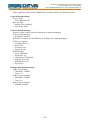
1
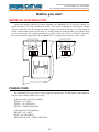
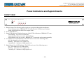
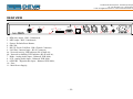
MAINTENANCE AND OPERATION
INSTRUCTION MANUAL
DB9000-STC
DSP-Based Stereo Generator
with
RDS/RBDS Encoder
Publish Date: 26-Nov-2012
Contents
Introduction......................................................................................................................................... 5
General Information........................................................................................................................... 6
Application....................................................................................................................................... 6
Product Features................................................................................................................................. 7
Technical Specifications................................................................................................................... 8
Block Diagram............................................................................................................................... 10
Safety Precautions............................................................................................................................. 11
Before you start................................................................................................................................. 12
Mains Voltage Selector . ................................................................................................................ 12
Power Cord ................................................................................................................................... 12
Operating Recommendations ........................................................................................................ 13
Radio Frequency Interference (RFI).............................................................................................. 13
Unpacking and Inspection................................................................................................................ 14
Mounting .......................................................................................................................................... 14
Rack Requirement ......................................................................................................................... 14
Heat Dissipation ........................................................................................................................... 14
Panel Indicators and Appointments................................................................................................ 15
Front View...................................................................................................................................... 15
Rear View....................................................................................................................................... 16
Connecting of DB9000-STC ............................................................................................................ 17
Analog Audio Inputs . .................................................................................................................... 17
Digital Audio Input......................................................................................................................... 17
LAN Port........................................................................................................................................ 17
RS-232 COM Port.......................................................................................................................... 17
Operation........................................................................................................................................... 18
Status.............................................................................................................................................. 20
General Configuration................................................................................................................... 22
Device Alias . ............................................................................................................................ 22
Date and Time........................................................................................................................... 22
Network Configuration................................................................................................................... 23
General Network Settings . ....................................................................................................... 23
IP Voice Announcement............................................................................................................. 24
WEB Server Settings . ............................................................................................................... 24
FTP Server Settings................................................................................................................... 24
SNMP Settings........................................................................................................................... 24
Backup Audio Configuration.......................................................................................................... 25
Audio Loss Settings .................................................................................................................. 25
Audio Recover Settings . ........................................................................................................... 25
MP3 Audio Player Settings ...................................................................................................... 26
RS-232 COM Port Configuration................................................................................................... 27
RS-232 Settings ........................................................................................................................ 27
Ethernet to RS-232 Redirector.................................................................................................. 27
Stereo Encoder Configuration........................................................................................................ 28
General Settings ....................................................................................................................... 28
Audio Input................................................................................................................................ 28
Injection Levels.......................................................................................................................... 28
Phase Adjustment...................................................................................................................... 29
MPX Limiter.............................................................................................................................. 29
Output Levels............................................................................................................................. 29
Audio Enhancement Configuration................................................................................................ 30
Automatic Gain Control Settings............................................................................................... 30
Audio Equalizer Settings........................................................................................................... 31
RDS Encoder Configuration.......................................................................................................... 32
RDS Encoder Settings................................................................................................................ 32
Program Station Name Settings................................................................................................ 32
Radio Text Settings.................................................................................................................... 33
General Settings........................................................................................................................ 33
Trafic Information...................................................................................................................... 34
Decoder Information................................................................................................................. 35
Date & Time Settings................................................................................................................. 35
Program Type Name Settings.................................................................................................... 35
Console Settings........................................................................................................................ 36
AF List Configuration.................................................................................................................... 37
Factory Defaults Settings . ............................................................................................................ 38
General Default Settings........................................................................................................... 39
Network Default Settings........................................................................................................... 39
Backup Audio Default Settings.................................................................................................. 39
COM Port Default Settings....................................................................................................... 40
Stereo Encoder Default Settings................................................................................................ 40
Audio Enhancement Default Settings........................................................................................ 40
RDS Encoder Default Settings................................................................................................... 41
AF List Default Settings........................................................................................................... 41
Hardware Reset.............................................................................................................................. 42
Network Default Settings........................................................................................................... 42
WEB Server Default Settings..................................................................................................... 42
Rebooting ...................................................................................................................................... 43
Firmware Update .......................................................................................................................... 44
RDS Console...................................................................................................................................... 45
Connecting to the RDS console...................................................................................................... 45
RDS Console Syntax....................................................................................................................... 45
List of available RDS Console commands and responses.............................................................. 46
UPnP discovery in Local Networks................................................................................................. 47
UPnP Activation................................................................................................................................ 48
WARRANTY TERMS AND CONDITIONS.................................................................................. 49
Product Registration Card............................................................................................................... 50
THIS PAGE
IS INTENTIONALLY
LEFT BLANK
65 Aleksandar Stamboliyski Str., 8000 Bourgas, Bulgaria
Tel: +359 56 820027, Fax: +359 56 836700
E-mail: [email protected] ,Web: www.devabroadcast.com
Introduction
DEVA Broadcast Ltd. was established in 1997 as a broadcasting and telecommunications
equipment importer for Bulgaria and Eastern Europe regions. Subsequently, DEVA Broadcast Ltd.
has developed and produced a wide range of low and mid power transmitters, RDS/RBDS Encoders
and Decoders, Modulation Monitors, Remote Controls, Site monitoring and other systems for
many companies. Our high degree engineers accomplish their bright ideas through successful
engineering, marketing and management in DEVA Broadcast Ltd.’s Headquarter in Bulgaria.
During the last ten years the company products have become our partners’ best sellers. After
detailed marketing analysis, our team has decided to launch its own brand products based on the
latest technologies in the broadcasting business. The company’s main goal is to design, develop
and offer a complete line of high quality and competitive products for FM and Digital Radio,
Radio Networks, Telecommunication Operators and regulation authorities. We base our market
authority position on our good after sales support and relation with the clients.
Since 2003 DEVA Broadcast Ltd. has been ISO 9001 certified .
The contractors of DEVA Broadcast Ltd. are satisfied with the permanent business comfort
and to their own confession they owe it to a great extent as well as their prosperity to the loyal
partnership of our company.
-5-
65 Aleksandar Stamboliyski Str., 8000 Bourgas, Bulgaria
Tel: +359 56 820027, Fax: +359 56 836700
E-mail: [email protected] ,Web: www.devabroadcast.com
General Information
DB9000-STC is a high-performance, 32bits DSP based Stereo Generator with built-in RDS/
RBDS encoder. It has been accurately designed to satisfy the most demanding requirements in FM
Stereo generation and advanced RDS/RBDS encoding. This Stereo Encoder accept both of types,
Analog and Digital AES/EBU audio sources. DB9000-STC comes with easy to use and password
protected Web Server and a comprehensive remote control features. It supports SNMP, RS232,
UDP, TCP/IP communication protocols. Its digital architecture guarantees long term reliability and
easy firmware updates, directly on field or from remote.
The built-in RDS encoder can ‘parse’ scrolling text, automatically breaking phrases into word
groups. It gives dynamic, on-the-fly programming access with its built-in USB, TCP/IP, UDP/
IP interfaces. This connectivity permits full integration of RDS/RBDS transmissions with the
station’s other networked functions, including message streams for digital radio and Webcasting. It
can be easily interfaced to various Automation Systems and offers an ASCII protocol for broadcast
song/artist information.
Another great feature of the DB9000-STC is that it can fight the dreaded dead air problem.
The DB9000-STC provides additional uncompromising security in case of loss of audio at the
audio inputs. The audio backup is presented as an integrated built-in MP3 audio player. The basic
principle of operation is that this unit can detect the silence and switch the output to the alternative
MP3 Player. The MP3 backup audio files and play lists can be uploaded in the device from your
PC using any FTP client. The audio storage capacity of DB9000-STC is 2 Giga Bytes.
Based on the latest DSP technology, the DB9000-STC is fully digital design for 24/7/365
operation. This product is the most cost effective, versatile and reliable solution designed for the
broadcasters looking for a complete solution for a single, or a multiple transmitter sites.
APPLICATION
•
•
•
•
On site DSP-Based Stereo and RDS encoding
Ethernet to RS-232 Redirector
Audio Backup on connection or audio loss
Audio Rebroadcast
-6-
65 Aleksandar Stamboliyski Str., 8000 Bourgas, Bulgaria
Tel: +359 56 820027, Fax: +359 56 836700
E-mail: [email protected] ,Web: www.devabroadcast.com
Product Features
•
•
•
•
•
•
•
•
•
•
•
•
•
•
•
•
•
•
•
•
•
•
Fully Digital 32 bits DSP Stereo Encoder
Excellent Audio Performances
Digital Volume Control of all Audio Inputs
Adjustable Pilot, L-R, RDS phases
Selectable pre-emphasis 0, 50µs, 75µs
Digitally adjustable Pilot & RDS injection levels
Fully Digital Synthesis of the RDS Signal
Intelligent Silence Detector and Backup Audio Player
Configuration and Monitoring via SNMP Ver.2C & WEB
Alert Notifications via E-mail, SNMP in case of Audio Loss
Lots of Storage for over 24 hours of non-repeating audio playback
Always Fresh Backup Audio Tracks with Embedded FTP server
Professional Balanced Stereo Analog Input on XLR connectors
Professional Digital AES/EBU Audio input on XLR connectors
Headphones Jack for local monitoring of the Audio Signal
Built-in MP3 Player with built in 2GB SD Card
UPnP for easy discovery in Local Networks
Professional 19 inches, 1U Professional rack mount chassis
Remote Firmware Upgrade for future-proof operation
Protected access to the device settings
Easy installation and operation
2 Years Warranty
-7-
65 Aleksandar Stamboliyski Str., 8000 Bourgas, Bulgaria
Tel: +359 56 820027, Fax: +359 56 836700
E-mail: [email protected] ,Web: www.devabroadcast.com
TECHNICAL SPECIFICATIONS
ANALOG AUDIO INPUT
Connector
Type
Impedance
Level
Sample rate
Dynamic range
DIGITAL AUDIO INPUT
Connector
Type
Resampling
AUDIO BACKUP
Trigger
Threshold
Trigger time
Storage
Supported file types
Playback modes
Remote file management
STEREO ENCODER
Type
Pre-emphasis
AGC
Equalizer
Stereo separation
Phase Adjust
Injection Levels Adjust
Output Connector
Output Level Adjust
Composite MPX Limiter
RDS ENCODER
Supported RDS Applications
Configuration
Automation control
Output Connector
Output Level Adjust
2 x XLR, Stereo
Balanced
600Ω or High Impedance
+6dBu / +12dBu, user selectable
96 kHz; Build-in sample rate converter used to produce lower
sample rates
>100dB
XLR
AES/EBU (IEC 60958)
Thru build-in sample rate converter
Audio Silence
Adjustable, -90dBFs to 0dBFs
Adjustable, 5s to 240s
SD Card, up to 2GB
*.MP3, *.AAC, *.M4A, *.M3U
Alphabetical ascending and descending, Shuffle, Playlist and
Shuffled playlist
Build-in FTP Server
Fully DSP Stereo Encoding
0, 50, 75µs
5 presets, 2 user defined
3-Band, ±12dB range
>55dB (typically >60dB)
Pilot, L-R, RDS
Pilot, RDS
BNC, Unbalanced
Digitally, up to 0dBu
6 presets, 3 user defined
PI, PS, Dynamic PS AF, RT, TP, TA, DI, M/S, PIN, PTY, PTYN
Web Interface
Remote TCP console
BNC, Unbalanced
Digitally, up to -6dBu
-8-
65 Aleksandar Stamboliyski Str., 8000 Bourgas, Bulgaria
Tel: +359 56 820027, Fax: +359 56 836700
E-mail: [email protected] ,Web: www.devabroadcast.com
PHONES AUDIO OUTPUT
Connector
Type
USER INTERFACE
Indicators
Web interface
RS-232
Type
Connector
Baud rates
Password protection
NETWORK
Connector
Type
1/4” (6.3mm) Phone Jack, Stereo
Headphones
4 LEDs on front panel, 2 LEDs on rear panel
Full control and status information
TCP/IP to RS-232 Redirector
DB-9, female
9600 to 115200
Yes
RJ-45
Ethernet
-9-
65 Aleksandar Stamboliyski Str., 8000 Bourgas, Bulgaria
Tel: +359 56 820027, Fax: +359 56 836700
E-mail: [email protected] ,Web: www.devabroadcast.com
BLOCK DIAGRAM
A simplified block diagram of DB9000-STC is shown below
POWER
LAN
RS-232
S/PDIF
RX
DSP
BACKUP PLAYER
WEB SERVER
FTP SERVER
RS-232 REDIRECTOR
RDS CONSOLE
SD CARD
DIGITAL
AUDIO
ADC
L ANALOG
R AUDIO
DAC
PHONES
D/A
COMPOSITE
MPX
DSP
STEREO ENCODER
RDS ENCODER
MPX LIMITER
AGC
EQUALIZER
RDS
Because of the all-digital, minimalist-discrete-component nature of device circuitry, we have not
provided schematic diagrams of the DB9000-STC in this Manual. Please, note that:
NO USER-SERVICEABLE COMPONENTS INSIDE.
REFER ALL SERVICING TO
QUALIFIED TECHNICAL PERSONNEL.
- 10 -
65 Aleksandar Stamboliyski Str., 8000 Bourgas, Bulgaria
Tel: +359 56 820027, Fax: +359 56 836700
E-mail: [email protected] ,Web: www.devabroadcast.com
Safety Precautions
IMPORTANT: Carefully read this paragraph as it contains important instructions concerning
operator safety and directions regarding the installation, operation and maintenance of the
equipment. Failure to observe the safety instructions and information given in this manual
constitutes an infringement of the safety rules and design specifications provided for this piece
of equipment. DEVA Broadcast Ltd. declines all responsibility if any one of the safety rules given
herein is not observed. DEVA Broadcast Ltd. declines all responsibility if the end-user resells the
product. The equipment is to be used by people capable of operating it in a trouble-free manner
and it is assumed that they are aware of the following safety rules.
◊ Keep this manual with the utmost care and close at hand so that it can be consulted whenever
needed
◊ After unpacking the equipment, check its condition.
◊ Avoid banging the equipment.
◊ The packing material (plastic bags, polystyrene, nails, etc.) must never be left within reach of
children, as these items are potential sources of danger.
◊ Do not use the equipment in places where the temperature is not within the recommended
range, as specified by the manufacturer.
◊ Before connecting the equipment, make sure the nameplate specifications correspond to the
mains electricity supply (the nameplate is located on the equipment enclosure).
◊ Do not remove the sticker from the equipment as it contains important specifications and the
relevant serial number.
◊ To join the equipment to the mains supply, use the power cord purchased with the equipment.
◊ The equipment must be used only for the purposes it was designed for.
◊ Abuse or misuse of the equipment is extremely dangerous for people, pets and property. The
manufacturer declines all responsibility for damage and injury resulting from improper use and
mishandling.
◊ Certain basic safety rules must be observed when using electrical equipment, in particular:
- Never touch the equipment with wet and/or damp hands or other parts of the body.
- Keep the equipment away from drops of water or sprinkling systems.
- Never use the equipment near high heat sources or explosive material.
- Do not introduce any extraneous matter into the equipment.
- Do not allow children or untrained people to use the equipment.
◊ Before cleaning or servicing the equipment outside, disconnect its power supply and wait at
least 2 seconds before working on it, as recommended by current safety regulations.
◊ In the event of faults and/or improper operation, turn off the equipment, shut off the electrical
power and call your dealer.
◊ Do not attempt to make repairs and/or adjustments when covers/guards or circuit boards are to
be removed.
◊ Call your dealer for any repairs and be certain original spare parts are used. Failure to observe
this rule may adversely affect the safety level of your equipment.
◊ The equipment is to be connected to the mains supply and provided with adequate and efficient
earth conductors.
◊ When installing, leave a clearance of at least 1 cm around the equipment to allow air to pass
freely.
- 11 -
65 Aleksandar Stamboliyski Str., 8000 Bourgas, Bulgaria
Tel: +359 56 820027, Fax: +359 56 836700
E-mail: [email protected] ,Web: www.devabroadcast.com
Before you start
MAINS VOLTAGE SELECTOR
Unless specifically ordered for export shipment, the DB9000-STC is set at the factory for
operation from 115V/230V, 50/60Hz AC mains. This can be confirmed by checking the voltage
selector inside the unit. To change the mains voltage, first remove the top cover of the unit. A
clearly marked slide switch is next to the AC mains connector on the encoder circuit board. With
power disconnected, use a small screwdriver to set the switch for 115VAC or 230VAC operation.
Be sure to install the appropriate fuse, DB9000-STC is equipped at the factory with 1A fuse.
115V
230V
POWER CORD
The detachable IEC-type power cord is supplied with the unit. The individual cord conductors
may be color-coded in either of two ways:
1) In accordance with US standards:
BLACK = AC “HOT”
WHITE = AC NEUTRAL
GREEN = EARTH GROUND
2) To European CEE standards:
BROWN = AC “HOT”
BLUE = AC NEUTRAL
GREEN/YELLOW = EARTH GROUND
- 12 -
65 Aleksandar Stamboliyski Str., 8000 Bourgas, Bulgaria
Tel: +359 56 820027, Fax: +359 56 836700
E-mail: [email protected] ,Web: www.devabroadcast.com
OPERATING RECOMMENDATIONS
For the normal and reliable operation of the DB9000-STC device we recommend to follow the
next list of instructions:
• Please, install the unit only in places with good air conditioning. The unit has been designed
for operation within an ambient temperature range extending from 10 to 50°C. But because
adjacent, less efficient equipment may radiate substantial second-hand heat, be sure that the
equipment rack is adequately ventilated to keep its internal temperature below the specified
maximum ambient. When installing, leave a clearance of at least 1 cm around the equipment
to allow air to pass freely.
• We do not recommend installation in rooms with high humidity, dusty places or other
aggressive conditions.
• Although it is expected that a DB9000-STC will be installed close to exciters (or transmitters
of even higher-power!), please practice reasonable care and common sense in locating the
unit away from abnormally high RF fields.
• Please, use only already checked power supply cables and sources. The shielded cables
usage is strongly recommended.
• We strongly recommend connecting the device only to reliable power supply sources. In
case of unstable power supply, please use UPS (Uninterruptible Power Supply).
• Please, use the device only with placed top cover to avoid any electromagnetic anomalies
which may cause problems of the normal functionality of the unit.
• Please, connect DB9000-STC only to good quality Internet connection. This is very important
for the normal remote operation of the unit.
• Please, check if your network settings pass through all the data traffic required for the normal
operation of the DB9000-STC unit.
RADIO FREQUENCY INTERFERENCE (RFI)
Although we have anticipated DB9000-STC installation in the immediate proximity of broadcast
transmitters, please do practice some care using the unit away from abnormally high RF fields.
- 13 -
65 Aleksandar Stamboliyski Str., 8000 Bourgas, Bulgaria
Tel: +359 56 820027, Fax: +359 56 836700
E-mail: [email protected] ,Web: www.devabroadcast.com
Unpacking and Inspection
IT IS VERY IMPORTANT that the Warranty Registration Card found at the front of this
Manual be completed and returned. Not only does this assure coverage of the equipment under
terms of the Warranty and provide a means of tracing lost or stolen gear, but the user will be sent
specific SERVICE OR MODIFICATION INSTRUCTIONS issued by DEVA Broadcast Ltd.
As soon as the equipment is received, inspect carefully for any shipping damage. If damage is
suspected, notify the carrier at once, and then contact DEVA Broadcast Ltd.
We recommend that you retain the original shipping carton and packing materials, just in
case return or reshipment becomes necessary. In the event of return for Warranty repair, shipping
damage sustained as a result of improper packing for return may invalidate the Warranty!
Mounting
RACK REQUIREMENT
The DB9000-STC mounts in a standard 19-inch equipment rack and requires only 1¾ inches
(1U) of vertical rack space. The use of plastic washers is recommended to protect the painted finish
around the mounting holes.
HEAT DISSIPATION
Consuming less power than the light in a refrigerator, the DB9000-STC itself generates
negligible heat. The unit is specified for operation within an ambient temperature range extending
from freezing to 120°F/50°C. But because adjacent, less efficient equipment may radiate substantial
heat, be sure that the equipment rack is adequately ventilated to keep its internal temperature
below the specified maximum ambient.
- 14 -
65 Aleksandar Stamboliyski Str., 8000 Bourgas, Bulgaria
Tel: +359 56 820027, Fax: +359 56 836700
E-mail: [email protected] ,Web: www.devabroadcast.com
Panel Indicators and Appointments
FRONT VIEW
DIGITAL STEREO & RDS/RBDS ENCODER
1
POWER
LEFT
BUSY
RIGHT
MODEL DB9000-STC
PHONES
2
3
4
5
1 - Phones Output. The following audio signals are reproduced through the headphones:
Voice Announcement of DB9000-STC IP Audio Decoder IP address upon startup;
Audio signal identical to that of the outputs audio;
2 - Power LED Indicator;
3 - Status LED Indicator. Blinking frequency of this LED is indication of DB9000-STC state:
Fast blinking – in process of connection;
Approximately twice per second – data buffering;
Approximately once per second – DB9000-STC is connected and operating normally;
4 - Left Channel Level LED Indicator. This LED can be in one of the following states:
Off - the channel level is within norms;
Blinking – indication of low signal level;
Constantly lit – indication of high signal level;
5 - Right Channel Level LED Indicator. This LED can in one of the following states:
Off - the channel level is within norms;
Blinking – indication of low signal level;
Constantly lit – indication of high signal level;
- 15 -
65 Aleksandar Stamboliyski Str., 8000 Bourgas, Bulgaria
Tel: +359 56 820027, Fax: +359 56 836700
E-mail: [email protected] ,Web: www.devabroadcast.com
REAR VIEW
6
RDS
1
MPX
4
2
RESET
7
LAN
RS-232
COM PORT
FUSE
SD CARD
11
3
5
6a
1 - RDS only output - BNC, Unbalanced;
2 - MPX ouput - BNC, Unbalanced;
3 - Factory Defaults Reset Button;
4 - SD Card;
5 - RS-232 Serial COM Port - DB-9 Female Connector;
6 - LAN Port / Internet Input – RJ-45 Connector;
6a - Network Activity LED Indicator (RJ-45 built-in);
6b - Network Availability LED Indicator (RJ-45 built-in);
7 - Right - Analog Audio Input – Balanced XLR Male;
8 - Left - Analog Audio Input – Balanced XLR Male;
9 - AES/EBU - Digital Audio Input – Balanced XLR Male;
10 - Fuse;
11 - Main Power Supply;
- 16 -
6b
9
8
RIGHT
LEFT
10
AES/EBU
65 Aleksandar Stamboliyski Str., 8000 Bourgas, Bulgaria
Tel: +359 56 820027, Fax: +359 56 836700
E-mail: [email protected] ,Web: www.devabroadcast.com
Connecting of DB9000-STC
ANALOG AUDIO INPUTS
Using a cable ending with two standard XLR connectors connect the analog signal source to the
analog audio inputs of DB9000-STC.
WARNING: Do not exceed maximum input level. This may permanently damage DB9000-STC.
DIGITAL AUDIO INPUT
Using a cable ending with a standard XLR connectors connect the AES/EBU signal source to
the digital audio input of DB9000-STC.
NOTE: As only one input can be managed by the encoder at a time, please select the preferred
signal source input – either analog or digital one. Selecting the preferred input can be performed
under CONFIGURATION menu (see “Audio Input” on page 28).
LAN PORT
For normal operation it is necessary DB9000-STC to be connected to a local network or Internet
by cable with RJ-45 connector.
RS-232 COM PORT
Using standart DB-9 cable connect DB9000-STC to any RS-232 compatible equipment.
- 17 -
65 Aleksandar Stamboliyski Str., 8000 Bourgas, Bulgaria
Tel: +359 56 820027, Fax: +359 56 836700
E-mail: [email protected] ,Web: www.devabroadcast.com
Operation
DB9000-STC is controlled through the built-in web server and a standard web browser can be
used to monitor its status or make some adjustments. To connect to the device you need to know
its IP address and follow the next steps:
• Open a WEB Browser.
• Enter the device IP address in the browser’s address field.
NOTE: If the port is different than the default one (80), it is necessary to specify it, e.g.
htpp://192.168.20.20:9000
• Press <ENTER>.
If you do not know the IP address you can hear it through the headphones when you turn on the
device. The other option to find out the IP address is using UPnP discovery in local networks (see
“UPnP discovery in Local Networks” on page 47).
The web interface consists of the following pages:
• Status
• Configuration
- General
- Network
- Backup Audio
- COM port
• MPX
- Stereo Encoder
- Audio Enhancement
- RDS Encoder
- AF List
• Factory Defaults
• Reboot
• Firmware Update
At the top of each page is located the Navigational Menu and underneath, on the left side is the
section with relevant information and adjustment fields. There is a kind of help section on the right
side, containing brief information about each of the fields on the left.
Hover your mouse over any of the left side fields to bring out a field’s description next to the
mouse pointer.
- 18 -
65 Aleksandar Stamboliyski Str., 8000 Bourgas, Bulgaria
Tel: +359 56 820027, Fax: +359 56 836700
E-mail: [email protected] ,Web: www.devabroadcast.com
The picture below is illustrating STATUS page opened:
NOTE: As shown on the picture below a Username and Password may be requested if the
Access Control is turned on and a page other then STATUS is selected (see “WEB Server Settings”
on page 24). Default values are user and pass.
- 19 -
65 Aleksandar Stamboliyski Str., 8000 Bourgas, Bulgaria
Tel: +359 56 820027, Fax: +359 56 836700
E-mail: [email protected] ,Web: www.devabroadcast.com
STATUS
On the picture below is shown the page with current device status:
This page contains information regarding current status of DB9000-STC as follows:
•
•
•
•
Audio Status;
Backup Audio Status;
Network Status
Other;
NOTE: Audio Status and Backup Status show the Left and Right channels peak levels which
are dynamically updated.
- 20 -
65 Aleksandar Stamboliyski Str., 8000 Bourgas, Bulgaria
Tel: +359 56 820027, Fax: +359 56 836700
E-mail: [email protected] ,Web: www.devabroadcast.com
Under Network Status are shown MAC address and current IP address, Network mask and
Gateway and the method in which they are assigned: Static Allocation or allocated by DHCP
server. Shown are also the primary and secondary DNS servers.
Connection Status is the place showing which one of the three available URLs is currently used,
device status (connected or disconnected), connection time, stream parameters and name.
Please note that if a compressed stream is used, Sample rate and Bitrate will be taken from the
stream. If the stream is in uncompressed format (PCM) then what is displayed for Sample rate and
Bitrate is what is set in the Configuration page.
Under Other are displayed DB9000-STC date and time.
In the upper right corner is located LIVE DATA icon. Clicking on the icon will toggle live data
ON and OFF as follows:
- live data is ON
- live data is OFF.
- 21 -
65 Aleksandar Stamboliyski Str., 8000 Bourgas, Bulgaria
Tel: +359 56 820027, Fax: +359 56 836700
E-mail: [email protected] ,Web: www.devabroadcast.com
GENERAL CONFIGURATION
Device Alias
Alias – Name of the device. This name is used to identify the device in a local network and is
used as title on all web pages. Up to 63 alpha-numeric characters can be entered.
Date and Time
Internet Time – Enable or disable automatic time synchronization from Internet. Default value:
Enabled.
Time Zone – Select local time zone of the device. Default value: GMT.
Local Date – a field where local date is to be entered. This field is only used when Internet Time
is disabled. Must be in dd/mm/yyyy format. Example: 31/12/2020.
Local Time – a field where local time is to be entered. This field is only used when Internet Time
is disabled. Must be in hh:mm:ss format. Example: 23:10:00.
Applying New Settings
In order new settings to take effect, it is necessary to press the SAVE button. Please keep in
mind that some of the new settings can reset DB9000-STC.
- 22 -
65 Aleksandar Stamboliyski Str., 8000 Bourgas, Bulgaria
Tel: +359 56 820027, Fax: +359 56 836700
E-mail: [email protected] ,Web: www.devabroadcast.com
NETWORK CONFIGURATION
General Network Settings
DHCP – As DHCP Client is used to automatically obtain the Network Settings it can be enabled
or disabled. Default value is Enabled.
IP Address – A field where static IP address is to be entered in case that DHCP client is not used.
Example: 192.168.0.2.
Netmask – A field where static subnet mask is to be entered. This parameter is not used if the
DHCP Client is enabled. Example for Netmask is: 255.255.255.0.
Gateway – A field where static gateway is to be entered. This parameter is not used if the DHCP
Client is enabled. Example for Gateway is: 192.168.0.1.
DNS 1 – A field where Static primary DNS server is to be entered. It is not used if the DHCP
Client is enabled. Example: 192.168.0.1
DNS 2 – A field where Static secondary DNS server to be entered. It is not used if the DHCP
Client is enabled. Example: 192.168.0.1
- 23 -
65 Aleksandar Stamboliyski Str., 8000 Bourgas, Bulgaria
Tel: +359 56 820027, Fax: +359 56 836700
E-mail: [email protected] ,Web: www.devabroadcast.com
IP Voice Announcement
IP Address – Enable or disable voice announcement of DB9000-STC’s IP Address. This future
is useful when the IP address is unknown, for example when it is obtained from the DHCP Server.
Default is Enabled.
WEB Server Settings
Port – This is the TCP port of the WEB Server. Default value is 80.
Username – User name for the WEB Server. Default value is user.
Password – Password for the WEB Server. Default value is pass.
NOTE: Username and Password are used in order to restrict the access to all configuration
pages. You can define Username only, Password only or both of them. If both Username and
Password are left blank, NO security is used.
FTP Server Settings
Command Port – TCP port where FTP server listens for connection. Default value is 21.
Data Port – TCP port where FTP server transfers data with the client. Default value is 2020.
Username – User name for the FTP Server. Default value is user.
Password – Password for the FTP Server. Default value is pass.
NOTE: Username and Password are used in order to restrict the access to the storage card and
all files on it. You can define Username only, Password only or both of them. If both Username and
Password are left blank, NO security is used.
SNMP Settings
SNMP MIB File: Press the Download button to download DB9000-STC SNMP MIB file.
NOTE: The MIB file may change from one firmware revision to the other. Downloading this
file from the device ensures that you have the proper MIB file.
Specify Agent ID, Agent Port, Read/Write Communities, Manager IP and Manager Port.
NOTE: Agent ID is used to identify the device among others when a SNMP notification is send.
Agent - enables/disables SNMP Agent.
Applying New Settings
In order new settings to take effect, it is necessary to press the SAVE button. Please keep in
mind that some of the new settings can reset DB9000-STC.
- 24 -
65 Aleksandar Stamboliyski Str., 8000 Bourgas, Bulgaria
Tel: +359 56 820027, Fax: +359 56 836700
E-mail: [email protected] ,Web: www.devabroadcast.com
BACKUP AUDIO CONFIGURATION
DB9000-STC has built-in backup audio player. It plays tracks from SD Card storage in case of
main audio signal loss. These tracks can be preloaded on the SD Card or be uploaded through the
built-in FTP server while DB9000-STC is operational.
Audio Loss Settings
Threshold – Audio level threshold for determining if audio signal is lost. Default value is -50
dB.
Time – Time to wait before switching to backup audio in case of audio signal loss. Default value
is 10 s.
Audio Recover Settings
Threshold – Audio level threshold for determining if audio signal is present. Default value is
-50 dB.
Time – Time to wait before switching back to main audio in case of audio signal recovery.
Default value is 10 s.
- 25 -
65 Aleksandar Stamboliyski Str., 8000 Bourgas, Bulgaria
Tel: +359 56 820027, Fax: +359 56 836700
E-mail: [email protected] ,Web: www.devabroadcast.com
MP3 Audio Player Settings
Playback Order – Select the order in which tracks are played by the backup player. There are
5 options:
-A-Z – plays all tracks in alphabetical, ascending order;
-Z-A – plays all tracks in alphabetical, descending order;
-Shuffle – plays all tracks in random order;
-Playlist – plays only tracks from the M3U playlist file, in the order they appear in it;
-Shuffled Playlist – plays only tracks from the M3U playlist file, but in random order;
Default value is Shuffle.
NOTES:
• All backup audio files must be located in a single folder named Audio;
• The folder must be in the root of the SD Card;
• No subfolders are allowed in this folder;
• The playlist file must be named playlist.m3u.
Applying New Settings
In order new settings to take effect, it is necessary to press the SAVE button. Please keep in
mind that some of the new settings can reset DB9000-STC.
- 26 -
65 Aleksandar Stamboliyski Str., 8000 Bourgas, Bulgaria
Tel: +359 56 820027, Fax: +359 56 836700
E-mail: [email protected] ,Web: www.devabroadcast.com
RS-232 COM PORT CONFIGURATION
DB9000-STC also acts as Ethernet to RS-232 redirector. You can connect any RS-232 compatible
equipment to DB9000-STC and communicate with it over the Internet.
RS-232 Settings
Baud rate – Select baud rate of the RS-232 COM Port. The external equipment must be
configured to the same baud rate. Default value is 9600.
Ethernet to RS-232 Redirector
Port – a field where TCP port of the Ethernet to RS-232 redirector is to be entered. This is the
TCP port used to communicate with any external device connected to the RS-232 COM Port.
Default value is 8001.
Password – Password for the RS-232 server. These are the first symbols that must be sent to
authenticate to the Ethernet to RS-232 redirector, otherwise the connection is dropped. If left blank
NO security is used. Default value is blank (empty).
- 27 -
65 Aleksandar Stamboliyski Str., 8000 Bourgas, Bulgaria
Tel: +359 56 820027, Fax: +359 56 836700
E-mail: [email protected] ,Web: www.devabroadcast.com
STEREO ENCODER CONFIGURATION
General Settings
Stereo Mode – Switch between Stereo and Mono Mode for MPX signal. Mono Mode disables
the 38 kHz sub-carrier.
Emphasis – The pre-emphasis operation consists of amplifying the high audio frequency levels
as compared to the low audio frequencies. The purpose of this is to reduce the signal/noise ratio
in a proportion of 10 to 15dB by performing the inverse operation at the receiving level. There is
50µS for Europe and 75µS for USA options available.
Audio Input
Input - select analog or digital input to be used
A/D Amplifier Gain - Analog input gain in the range from -6 to +18 dB. Default level is 0 dB
Injection Levels
Pilot Tone – Here can be adjusted modulation level of the pilot tone as a component of the
MPX signal.
RDS – Modulation level of the RDS can be adjusted from 0 to 12% from the overall MPX
signal level.
- 28 -
65 Aleksandar Stamboliyski Str., 8000 Bourgas, Bulgaria
Tel: +359 56 820027, Fax: +359 56 836700
E-mail: [email protected] ,Web: www.devabroadcast.com
Phase Adjustment
Phase of the Pilot Tone, L-R sub-carrier (38 kHz) and RDS sub-carrier (57 kHz) are factory
adjusted. Additional adjustments can be made by the user providing more flexibility in DB9000-STC
settings.
MPX Limiter
Enable – Enable or Disable the MPX Limiter.
Preset – There are three factory and three user configurable presets available. Users can set their
own Limiter presets by changing following parameters:
- Attack time – the period when the limiter is decreasing gain to reach the level that is determined
by the ratio.
- Release time – the period when the limiter is increasing gain to the level determined by the
ratio, once the level has fallen below the threshold.
- Averaging time – the period between each of the input samples of the limiter.
- Threshold – the input level above which the signal is reduced.
- Ratio – determines the input/output ratio for signals above the threshold.
Output Levels
MPX output – Select output level of the MPX signal. It can be adjusted in the range -72 to +12
dBu in 1.5 dB steps. Default value is +6 dBu.
RDS output – Select output level of the RSD signal. It can be adjusted in the range -72 to +6
dBu in 1.5 dB steps. Default value is 0 dBu.
Applying New Settings
In order new settings to take effect, it is necessary to press the SAVE button. Please keep in
mind that some of the new settings can reset DB9000-STC.
- 29 -
65 Aleksandar Stamboliyski Str., 8000 Bourgas, Bulgaria
Tel: +359 56 820027, Fax: +359 56 836700
E-mail: [email protected] ,Web: www.devabroadcast.com
AUDIO ENHANCEMENT CONFIGURATION
Automatic Gain Control Settings
Enable – Enable or Disable the Automatic Gain Control.
Preset – There are three factory and two user configurable presets available. Users can set their
own AGC presets changing the following parameters:
- Attack time – the period when the AGC is increasing gain to reach the ‘Gain’ level, when the
input level is below the level set in ‘Gain’.
- Release time – the period when the AGC is decreasing gain to the level determined by the
‘Gain’, once the level has exceeded the level set in ‘Gain’.
- Gain – the input level above which the signal increases its gain. Note that applied gain is
only positive.
- Max gain up – To avoid excessive gains that can amplify the noise in a quiet program, ‘Max
gain up’ must be set according to the program.
- 30 -
65 Aleksandar Stamboliyski Str., 8000 Bourgas, Bulgaria
Tel: +359 56 820027, Fax: +359 56 836700
E-mail: [email protected] ,Web: www.devabroadcast.com
Audio Equalizer Settings
63 Hz – gain -12dB to +12dB.
630 Hz – gain -12dB to +12dB.
6300 Hz – gain -12dB to +12dB.
NOTE: Applied equalizer gain must be set according to the level of specified frequency and
overall level of this frequency. To avoid audio distortion the overall level of this frequency must
not exceed 0dB.
Applying New Settings
In order new settings to take effect, it is necessary to press the SAVE button. Please keep in
mind that some of the new settings can reset DB9000-STC.
- 31 -
65 Aleksandar Stamboliyski Str., 8000 Bourgas, Bulgaria
Tel: +359 56 820027, Fax: +359 56 836700
E-mail: [email protected] ,Web: www.devabroadcast.com
RDS ENCODER CONFIGURATION
RDS Encoder Settings
Enable – General Enable or Disable RDS Encoder.
Program Station Name Settings
PS Static – The 8-character PS field is for the “street name” of the station. This will appear on
the radio faceplate whenever a dynamic, scrolling – PS message is not being transmitted.
PS Dynamic – We provide Dynamic PS in block mode because of our concern over distracted
car drivers. Viewing a message in the block mode (complete words or groups of words), a driver
must pay close attention to the radio display, or risk missing part of the message. Although the
message may be repeated over and over, the driver may tune in at the end of a song, and in finding
out who sang the number could rear-end the car in front.
Dynamic PS ‘marches’ the message across the display screen one character at a time. The
message requires a much longer transmission time in this mode, but a glance at the radio display a
few seconds still allows the driver to get the full message without missing words.
DPS Scroll Step – DPS Scroll Step is used in the “block” mode of message transmission,
the more popular ‘grouped-word’ method. Once ‘DPS Scroll Step’ options are set, this encoder
function is valid for any scrolling-PS message, whether it is entered into the static DPS register,
- 32 -
65 Aleksandar Stamboliyski Str., 8000 Bourgas, Bulgaria
Tel: +359 56 820027, Fax: +359 56 836700
E-mail: [email protected] ,Web: www.devabroadcast.com
or received as ASCII text from station automation. Very short words are sent together in groups.
For instance, THIS IS constitutes seven characters that can be sent as a group. The same would
hold true for OF THE or NOW HERE. Longer words, up to and including 8 characters, are sent
individually: WARNING or DOUGHNUT or BICYCLE. The device can either center words that
are sent individually on the radio display or left-justify them. This will be covered along with the
function of the ‘DPS Scroll Step’. Words that exceed the available 8 characters are ‘sidestepped’
through two or more consecutive displays. Examples: EMERGENC followed by MERGENCY,
or SUPERMAR followed by UPERMARK and PERMARKE and ERMARKET. This method of
splitting words gives a good sense of continuity and readability.
Setting ‘DPS Scroll Step’ to 1 will scroll the message one character at a time, as described. Other
numbers also safe-scroll the message, but at 2, 3, 4, and up to 8 characters at a time. Selecting 9
will parse, as described, but text will be left-justified rather than centered on the display. 2 through
8 may be useful in some special RDS applications, but 0 and 1 are the primary ‘DPS Scroll Step’
selections. To recap: 0 will enable the more-popular, centered-auto-parsed block mode and 1 the
Dynamic PS, letter-by-letter option.
DPS Scroll Speed – The speed of dynamic PS messaging is set here, or dynamic PS messaging
can be turned off entirely. When OFF is selected, the dynamic PS message remains in the nonvolatile encoder memory, but only the 8-character default static “street name” typed into the PS
field will be displayed on the receiver faceplate. Setting the speed at 1 will result in the slowest
refresh rate of the ‘block’ message, or slowest Safe Scrolling. 9 is the fastest speed, but many RDS
radios display gibberish at high speed settings. The display should be stable with any radio at a
speed setting of 7 or lower.
Radio Text Settings
Radio Text – This is a 64-character block of plain text that the listener can select for visual
display on the faceplate of the radio by pressing an INFO button on the receiver. This function is
not available on many automobile radios for safety reasons, which has precipitated the frownedupon practice of scrolling the PS field instead. Most radios have limited alphanumeric display
capability, so the 64 characters of Radio Text march across the front panel, much akin those
annoying LED advertising signs found in airport buses or fast food emporia. Like the Dynamic PS
implementation, Radio Text can announce song titles and performers, run special promotions or
contests, or broadcast sponsors’ messages.
RT Speed – The Radio Text update rate is programmed by setting RT Speed =n , with n a number
between 1 and 9, corresponding to a refresh rate between slow and fast, respectively. Keeping
the throughput tradeoff in mind, unless Radio Text is being used for contests or for other quasidynamic activities, it is best to use a lower number. A rate of 1, 2 or 3 will make little difference in
the speed of other RDS functions.
NOTE: Radio Text can be turned off entirely by setting: RT Speed =0. A zero value in this field
turns the Radio Text message off, but does not delete any saved message from memory.
General Settings
PI – Program Identification: This block of data identifies the broadcast station with a
hexadecimal numerical code, which becomes the “digital signature” of the station. The code is
assigned by the broadcasting authority in most countries, but in the US it is calculated from a
numerical encoding of station call letters. The receiver processes the PI code to assist automatic
tuning features (station memories), and to prevent false switching to alternative frequencies that
might be shared by broadcasters in nearby regions.
PTY – Program Type: The PTY data flag identifies the station format from a collection of
pre-defined categories. Many RDS receivers are able to seek the listener’s preferred format
automatically. This means that a car radio can switch from a fading station to a stronger one
- 33 -
65 Aleksandar Stamboliyski Str., 8000 Bourgas, Bulgaria
Tel: +359 56 820027, Fax: +359 56 836700
E-mail: [email protected] ,Web: www.devabroadcast.com
that carries the same variety of music, though not the very same program, as provided by AF
switching. The PTY function of RDS helps a broadcaster catch ‘transient audience’ share. Under
some programming circumstances, the PTY identifier may be made ‘dynamic,’ changing between
categories for a station that “dayparts” (changes its format for specific time periods). The PTY
code is not meant to change from song to song or to accommodate a top-of-the-hour newscast,
however.
M/S – Music / Speech Switch: This flag simply indicates whether music or speech is the primary
broadcast programming. The purpose of this function is not well explained in the respective
Standards, hence it comes as no surprise that it is not widely used.
Trafic Information
TP – Traffic Program Identification: The TP flag identifies the station as one that routinely
broadcasts traffic bulletins for motorists as part of its normal, everyday programming. When the
TP flag is displayed on the receiver faceplate, the radio is searching for traffic announcements. The
radio keeps track of TP stations offering this service to speed up the search-and-switch process.
TA – Traffic Announcement: This is a temporary flag added to the RDS data stream only as a
traffic bulletin is being aired. Some RDS car radios can be set to search for traffic bulletins among
various TP stations (see TP) while tuned to a listener’s preferred program, or even while playing
a tape or CD. As soon as any TP station broadcasts a traffic bulletin, the receiver temporarily
switches-over to receive it. When the bulletin is finished, the receiver switches back to the original
program, tape or CD.
- 34 -
65 Aleksandar Stamboliyski Str., 8000 Bourgas, Bulgaria
Tel: +359 56 820027, Fax: +359 56 836700
E-mail: [email protected] ,Web: www.devabroadcast.com
Decoder Information
DI – Decoder Information: This is one of several ‘flags’ that convey yes/no or other very basic
data. This particular flag tells the receiver whether the broadcast is monaural, or is being transmitted
in any of several methods of stereo or binaural broadcasting. As many as 16 encoding options may
be accommodated! This is a rather esoteric function and, thus far, remains unused both in Europe
and in the US.
Date & Time Settings
Enable – Enable/Disable type 4A Group Transmission.
Program Type Name Settings
Enable – Enable/Disable type 10A Group Transmission. This group allows further description
of the current Program Type.
PTYN – Program Type Name (PTYN) (for display) is transmitted as 8-bit characters. PTYN
must only be used to enhance Program Type information and it must not be used for sequential
information.
- 35 -
65 Aleksandar Stamboliyski Str., 8000 Bourgas, Bulgaria
Tel: +359 56 820027, Fax: +359 56 836700
E-mail: [email protected] ,Web: www.devabroadcast.com
Console Settings
Port – a field where TCP port of the RDS console is to be entered. This console is used to edit
RDS settings in real time. Default value is 8000.
Password – Password for the RDS console. These are the first symbols that must be sent to
authenticate to the RDS console, otherwise the connection is dropped. If left blank NO security is
used. Default value is blank (empty).
NOTE: For more information about the RDS console see chapter “RDS Console”.
Applying New Settings
In order new settings to take effect, it is necessary to press the SAVE button. Please keep in
mind that some of the new settings can reset DB9000-STC.
- 36 -
65 Aleksandar Stamboliyski Str., 8000 Bourgas, Bulgaria
Tel: +359 56 820027, Fax: +359 56 836700
E-mail: [email protected] ,Web: www.devabroadcast.com
AF LIST CONFIGURATION
On the above picture is displayed Alternative Frequencies List Configuration Page, consisting
of 25 AF settings:
AF xx – Select alternative frequency of current program. You can choose from 207 standard AF
list options as defined in the RDS/RBDS standard.
-The first option is Disabled, meaning this AF is not used. The first disabled AF ends the AF
list;
-The second option is LW/MW Follows. This is not an AF, but a special symbol. It means the
next AF in the list is in the LW/MW frequency range.
-The third option is Filler. This is not an AF, but a special symbol used to pad the AF list to even
length;
-Each of the rest of the options corresponds to a specific FM or LW/MW frequency.
- 37 -
65 Aleksandar Stamboliyski Str., 8000 Bourgas, Bulgaria
Tel: +359 56 820027, Fax: +359 56 836700
E-mail: [email protected] ,Web: www.devabroadcast.com
FACTORY DEFAULTS SETTINGS
On the above picture is shown the Factory Defaults page. Restoring DB9000-STC to its Factory
Defaults can be done by following the next steps:
• Press the “Restore” button.
• A new window as the one shown below will appear:
• Confirm that you want to restore factory defaults.
• Wait for the process to complete.
NOTE: All the settings will be restored to their factory defaults except the Network Settings,
which will remain the same.
- 38 -
65 Aleksandar Stamboliyski Str., 8000 Bourgas, Bulgaria
Tel: +359 56 820027, Fax: +359 56 836700
E-mail: [email protected] ,Web: www.devabroadcast.com
Upon completion of the process DB9000-STC settings will have the following values:
General Default Settings
Device Alias:
• Alias: DB9000-STC
Date and Time:
• Internet Time: Enabled
• Time Zone: GMT
Network Default Settings
General: All the General Network Settings will remain unchanged.
IP Voice Announcement:
• IP Address: Enabled
WEB Server Settings: All the WEB server Settings will remain unchanged.
FTP Server Settings:
• Command Port: 21
• Data: 2020
• Username: user
• Password: pass
SNMP Settings:
• Agent : Disabled
• Agent Port: 161
• Community: DEVA9000
• Manager IP: 0.0.0.0
• Manager Port: 162
• Agent ID: 0
Backup Audio Default Settings
Audio Loss Settings:
• Threshold: -50 dBFs
• Time: 10 s
Audio Recover Settings:
• Threshold: -50 dBFs
• Time: 10 s
Backup Player Settings:
• Playback: Shuffle
- 39 -
65 Aleksandar Stamboliyski Str., 8000 Bourgas, Bulgaria
Tel: +359 56 820027, Fax: +359 56 836700
E-mail: [email protected] ,Web: www.devabroadcast.com
COM Port Default Settings
RS-232 Settings:
• Baud rate: 9600
Ethernet to RS-232 Redirector:
• Port: 8001
• Password: blank (empty)
Stereo Encoder Default Settings
General Settings :
• Stereo Mode: Stereo
• Emphasis: 50µS
Injection Levels:
• Pilot Tone: 10 %
• RDS: 5 %
Phase Adjustment: All phase are at 0º.
MPX Limiter:
• Enable: Disabled
• Preset: Mid
• Attack time: 100 ms
• Release time: 500 ms
• Averaging: 10 ms
• Threshold: -15 dB
• Ratio: 4:1
Output Levels:
• MPX output: +6 dBu
• RDS output: 0 dBu
Audio Enhancement Default Settings
Automatic Gain Control Settings:
• Enable: Disabled
• Preset: Mid
• Attack time: 3000 ms
• Release time: 10 ms
• Gain: -3 dB
• Max gain up: 10 dB
Audio Equalizer Settings:
• 63 Hz: 0dB
• 630 Hz: 0dB
• 6300 Hz: 0dB
- 40 -
65 Aleksandar Stamboliyski Str., 8000 Bourgas, Bulgaria
Tel: +359 56 820027, Fax: +359 56 836700
E-mail: [email protected] ,Web: www.devabroadcast.com
RDS Encoder Default Settings
RDS Encoder Settings:
• Enable: Enabled
Program Station Name Settings:
• PS Static: DB9000
• PS Dynamic: DB9000-STC Stereo Coder & RDS Encoder
• DPS Scroll Step: 0 – centered
• DPS Scroll Speed: 0 – DPS off
Radio Text Settings:
• Radio Text: DB9000-STC Stereo Coder & RDS Encoder
• RT Speed: 4
General Settings:
• PI: 1234
• PTY: 0
• M/S: Speech
Trafic Information:
• TP: Off
• TA: Off
Decoder Information:
• DI: Mono, Not Artificial Head, Not Compressed, Static PTY
Date & Time Settings:
• Enable: Disabled
Program Type Name Settings:
• Enable: Disabled
• PTYN: blank field
Console Settings:
• Port: 8000
• Password: blank (empty)
AF List Default Settings
All AFs are diasabled.
- 41 -
65 Aleksandar Stamboliyski Str., 8000 Bourgas, Bulgaria
Tel: +359 56 820027, Fax: +359 56 836700
E-mail: [email protected] ,Web: www.devabroadcast.com
HARDWARE RESET
This process will fully restore DB9000-STC to its Factory Defaults, including the Network
settings. Hardware Reset can be done by following the next steps:
• Disconnect the power supply cable from the unit.
• Locate the RESET button on Rear panel.
• Press and hold the RESET button.
• Connect the power supply cable to the unit.
• Keep the RESET button pressed until the POWER led starts blinking.
• Release the RESET button.
• Wait for DB9000-STC to reboot with the factory default settings.
Upon completion of the process DB9000-STC settings will have the following values:
Network Default Settings
• DHCP: enabled
WEB Server Default Settings
• Port: 80
• Username: user
• Password: pass
All other settings will have the factory default values described in chapter “Factory Defaults
Settings”.
NOTE: After the process completes the DHCP Client is enabled. The DB9000-STC will obtain
IP Address from DHCP server shortly.
ATTENTION: Please note that the WEB Server’s Port, Username and Password will be
changed, so it is possible the page not to be loaded after restoring factory defaults. You may be
asked to re-enter the encoder’s address and/or username and password.
- 42 -
65 Aleksandar Stamboliyski Str., 8000 Bourgas, Bulgaria
Tel: +359 56 820027, Fax: +359 56 836700
E-mail: [email protected] ,Web: www.devabroadcast.com
REBOOTING
On the above picture is shown the Reboot page. Rebooting of DB9000-STC can be done by
following the next steps:
• Press the “Reboot” button.
• The following dialog warning window will appear:
• Confirm that you want to reboot the device.
• Wait for the process to complete.
- 43 -
65 Aleksandar Stamboliyski Str., 8000 Bourgas, Bulgaria
Tel: +359 56 820027, Fax: +359 56 836700
E-mail: [email protected] ,Web: www.devabroadcast.com
FIRMWARE UPDATE
On the above picture is shown the Firmware Update page. To update the device firmware,
please follow the next steps:
• Select the new firmware file.
• Press the “Upload” button.
• The following dialog window will appear:
• Wait for the process to complete.
- 44 -
65 Aleksandar Stamboliyski Str., 8000 Bourgas, Bulgaria
Tel: +359 56 820027, Fax: +359 56 836700
E-mail: [email protected] ,Web: www.devabroadcast.com
RDS Console
CONNECTING TO THE RDS CONSOLE
The RDS Console is used to edit RDS settings in real time. For example it can be used by
automation software.
To use the console do the following steps:
1. Connect to the TCP port of the RDS console with a terminal program or an automation
software.
2. Wait to receive the welcome message.
3. Enter the password, if used.
4. Proceed with entering commands.
RDS CONSOLE SYNTAX
The picture above is a sample RDS console conversation. The red text represents user input
and black text represents the console’s responses. The symbol ‘8 ’ represent the Enter key on the
keyboard.
The first row is the welcome message from the RDS console. Next the user types in the password
(in this case ‘pass’), followed by Enter. The third row is the response meaning that the password is
accepted and user may proceed with commands.
The fourth row is a ‘set’ command. These types of commands are used to set new value to RDS
parameters. In the example above ‘PI’ is the Program Identification command, ‘=’ (equal sign)
means set new value and ‘1234’ is the new value. The Enter key represents command’s end and
signals the RDS console to execute the command. The fifth row is a positive response from the
RDS console. It means the command is accepted and executed successfully.
The sixth row is a ‘get’ command. These types of commands are used to return the current
value of RDS parameters. In the example above ‘PI’ is the Program Identification command, ‘?’
(question mark) means return PI’s value. The RDS console responds with the current value (in this
case ‘1234’) and positive response on the next row.
The ninth row is again a ‘set’ command. In this case: Set Traffic Program to 3. The response is
negative because the parameter TP can only have value 0 or 1.
- 45 -
65 Aleksandar Stamboliyski Str., 8000 Bourgas, Bulgaria
Tel: +359 56 820027, Fax: +359 56 836700
E-mail: [email protected] ,Web: www.devabroadcast.com
LIST OF AVAILABLE RDS CONSOLE COMMANDS
AND RESPONSES
PARAMETER
Program Identification
Program Service Name
Dynamic PS
COMMAND
PI
PS
DPS
Dynamic PS Speed
Dynamic PS Method
DPSS
PARSE
Program Type
Traffic Program
Traffic Alert
Alternative Frequencies
xx denotes AF number
between 1 and 25
Decoder Information
M/S
RadioText
RadioText Speed
PTY
TP
TA
AFxx
DI
MS
TEXT
DRTS
Command Echo
ECHO
SPECIAL COMMAND
=
MEANING
Set parameter value. Following a parameter command sets new value
to that parameter;
e.g.: PI=1234
Get parameter value. Following a parameter command returns status of
encoder memory for that parameter;
e.g.: AF3?
Returns all data in encoder memory.
Initializes the encoder to all factory defaults.
?
??
INIT
RESPONSE
HELLO
PASSOK
PASSFAIL
OK
NO
BYE
(NO RESPONSE)
DATA ENTRY
4 digit HEX number (station “digital address”)
8 (max) ASCII characters (station “street name”)
64 (max) ASCII characters (for messaging in PS
field)
0 to 9 (0 = Off, 1 = slow, 9 = fastest)
0 through 9 (0 = parsed, centered; 1-8 Safe Scrolling;
9 = parsed, left)
1 or 2 digit number (describes station format)
0 or 1 (0 = no, 1 = yes)
0 or 1 (0 = flag off, 1 = flag on)
0 to 204 (0 = blank; 1 to 204 = “channel” in 100 kHz
increments, 87.6 MHz to 107.9 MHz)
1 digit HEX number
0 or 1 (0 = speech-only, 1 = music)
64 (max) ASCII characters
0 to 9 (0 = Radiotext off; 1 to 9 = update rate, slow
to fast)
0 or 1 (0 = echo off, 1 = echo on)
MEANING
Welcome message when connection to the console is established.
If security is enabled proceed with entering the password. Otherwise
proceed with commands.
Password accepted, may proceed with commands.
Wrong password. Connection is dropped immediately.
Command received by encoder properly formatted and understood.
Command properly formatted but data not understood.
Console has been inactive for more than 30 minutes and the connection
will be dropped. User needs to connect again to enter more commands.
Data sent is ignored by DB9000-STC.
- 46 -
65 Aleksandar Stamboliyski Str., 8000 Bourgas, Bulgaria
Tel: +359 56 820027, Fax: +359 56 836700
E-mail: [email protected] ,Web: www.devabroadcast.com
UPnP discovery in Local Networks
DB9000-STC implements UPnP which lets you easily find it in your local network. For this
purpose your system should have UPnP enabled (see “UPnP Activation” on page 48). To discover
the device follow the next steps:
•
•
•
•
Connect the device to the local network.
Open “My Network Places” on your computer.
Find the decoder’s icon.
Double click it to open the DB9000-STC web interface.
- 47 -
65 Aleksandar Stamboliyski Str., 8000 Bourgas, Bulgaria
Tel: +359 56 820027, Fax: +359 56 836700
E-mail: [email protected] ,Web: www.devabroadcast.com
UPnP Activation
NOTE: The following explanations apply to Windows XP SP2 or SP3! If you use another
operating system, please contact your system administrator.
Open “My Network Places”. If you have the caption displayed in the picture below, click on it.
Then click “Yes” and wait for the process to complete. Now you should see the device. If you still
have troubles finding the device, please see
http://support.microsoft.com/kb/941206 or contact your system administrator.
- 48 -
65 Aleksandar Stamboliyski Str., 8000 Bourgas, Bulgaria
Tel: +359 56 820027, Fax: +359 56 836700
E-mail: [email protected] ,Web: www.devabroadcast.com
WARRANTY TERMS AND CONDITIONS
I. TERMS OF SALE: DEVA Broadcast Ltd. products are sold with an understanding of “full
satisfaction”; that is, full credit or refund will be issued for products sold as new if returned to the
point of purchase within 30 days following their receipt, provided that they are returned complete
and in an “as received” condition.
II. CONDITIONS OF WARRANTY: The following terms apply unless amended in writing
by DEVA Broadcast Ltd.
A. The Warranty Registration Card supplied with this product must be completed and returned
to DEVA Broadcast Ltd. within 10 days of delivery.
B. This Warranty applies only to products sold “as new.” It is extended only to the original enduser and may not be transferred or assigned without prior written approval by DEVA Broadcast Ltd.
C. This Warranty does not apply to damage caused by improper mains settings and/or power
supply.
D. This Warranty does not apply to damage caused by misuse, abuse, accident or neglect. This
Warranty is voided by unauthorized attempts at repair or modification, or if the serial identification
label has been removed or altered.
III. TERMS OF WARRANTY: DEVA Broadcast Ltd. products are warranted to be free from
defects in materials and workmanship.
A. Any discrepancies noted within TWO YEARS of the date of delivery will be repaired
free of charge, or the equipment will be replaced with a new or remanufactured product at
DEVA Broadcast Ltd. option.
B. Parts and labor for factory repair required after the one-year Warranty period will be billed
at prevailing prices and rates.
IV. RETURNING GOODS FOR FACTORY REPAIR:
A. Equipment will not be accepted for Warranty or other repair without a Return Authorization
(RA) number issued by DEVA Broadcast Ltd. prior to its return. An RA number may be obtained
by calling the factory. The number should be prominently marked on the outside of the shipping
carton.
B. Equipment must be shipped prepaid to DEVA Broadcast Ltd.. Shipping charges will be
reimbursed for valid Warranty claims. Damage sustained as a result of improper packing for return
to the factory is not covered under terms of the Warranty and may occasion additional charges.
- 49 -
65 Aleksandar Stamboliyski Str., 8000 Bourgas, Bulgaria
Tel: +359 56 820027, Fax: +359 56 836700
E-mail: [email protected] ,Web: www.devabroadcast.com
PRODUCT REGISTRATION CARD
• All fields are required, or warranty registration is invalid and void
Your Company Name
Contact
Address Line 1
Address Line 2
City
State/Province
ZIP/Postal Code
Country
E-mail
Phone
Fax
Which DEVA Broadcast Ltd. product did you purchase?
Product Serial #
Purchase date
/
/
Installation date
/
/
Your signature*
*Signing this warranty registration form you are stating that all the information provided to DEVA Broadcast Ltd. are truth and correct.
DEVA Broadcast Ltd. declines any responsibility for the provided information that could result in an immediate loss of warranty for
the above specified product(s).
Privacy statement: DEVA Broadcast Ltd. will not share the personal information you provide on this card with any other parties.
- 50 -