1
VLT ELECTRONIC CABINET
COOLING SYSTEM
USER MANUAL
VLT-MAN-ESO-17130-1603
Issue: 1.0
Date: 27 Apr. 98
Page: 19of 57
The results of these checks are stored in the FEPROM status register.
In case of failure, a warning message is displayed. In this case the controller is faulty and should be
substituted.
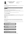
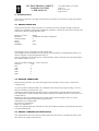
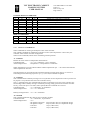
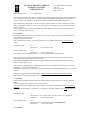
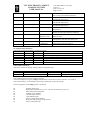
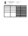
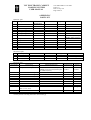
The structure of the FEPROM status register is as follows:
b0
writing on FEPROM
b1
block identifier
b2
block identifier
b3
reserved
b4
reserved
b5
write error
b6
no more space available in FEPROM
b7
checksum error on block specified by b1,b2
7.2.4 PI REGULATOR CHECKS
Some checks are performed on the level of the numeric signals inside the PI regulator.
If the (absolute value of the) input to the regulator (i.e. the tracking error) exceeds the parameter in PI
regulator/Regulator params/Err lim (default 5°C), the output of the controller is saturated to the
maximum or minimum value.
The absolute value of the integrator is also checked. If its value exceeds the value of the parameter in
regulator/Regulator params/Int sat, (default: about 500E6), the integrator is saturated.
No warning messages are displayed when these conditions are detected.
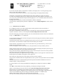
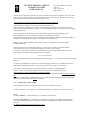
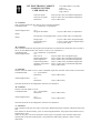
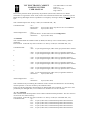
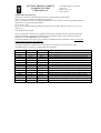
The structure of the corresponding status register is:
b0
main integrator overflow flag
b1
main integrator underflow flag
b2
main error overflow flag
b3
main error underflow flag
b4
PI regulator enable
b5
reserved
b6
reserved
b7
reserved
This status register cannot be accessed from the local interface; it is readable from the host.
Only bit b4, which enables/disables the PI regulator, can be set/cleared from menu PI
regulator/status.
7.2.5 COMMUNICATIONS STATUS
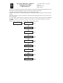
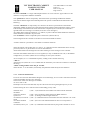
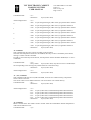
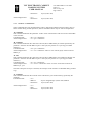
Errors detected during the communication are reported in the communication status register, whose
structure is as follows:
b0
reserved
b1
reserved
b2
rlost: character received before last message read
b3
rovferr: too long message received
b4
recmess: received message ready
b5
chkerr: checksum error in received message
b6
rxon: header received
b7
txon: transmitting a message
No warning errors are displayed in case these errors are detected. This register is read-only.
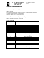
7.2.6 POWER-UP RESET
The controller contains a watch-dog circuit which resets the microprocessor if the execution of the
firmware for any reason jams.