1
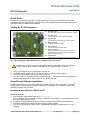
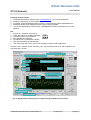
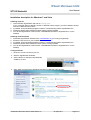
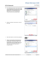
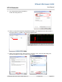
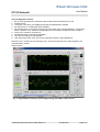
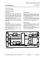
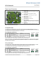
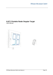
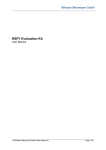
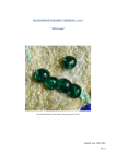
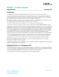
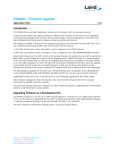
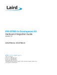
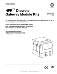
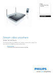
ST100 Starterkit User Manual © 2010 RFbeam Microwave GmbH www.rfbeam.ch 05-April-2011 Page 1/17 User Manual ST100 Starterkit Quick Start RFbeam ST100 Starterkit consists of a PCB motherboard, a K-LC1 radar module and a flexible acquisition software called RFbeam SignalViewer. ST100 hardware serves as "USB sound system" without the need of installing driver software. Setting Up ST100 Hardware X1 High Gain Input For native radar modules without integrated IF amplifier X4 X2 Low Gain Input For radar modules with integrated IF amplifier X5 X3 Direct IF Input For modules with integrated high gain IF amplifier X2 X4 9VDC (optional) If ST100 is used without USB X3 X6 X1 Sel X5 USB-1 Interface For use with RFbeam SignalViewer X6 Signal Testpoints Connect multimeters and oscilloscope to view raw signals. Contains also analog outputs to playback recorded radar waveforms. Sel Input Selector Signals to be sent to RFbeam SignalViewer Software Fig. 1:ST100 Starterkit with RFbeam K-LC1 plugged into X1 connector RFbeam K-LC1 radar module is susceptible to electrical discharge . Before plugging the module, please touch first the ST100 board and then insert the K-LC1 device. 1. 2. 3. 4. Plug in your RFbeam K-LC1 module into connector X1. Set all DIP switch positions to "OFF". This will select X1 with high gain amplifier. Connect ST100 hardware with a USB cable to your PC. Your PC will show messages like "new hardware found" ... ST100 acts as an audio subsystem. Windows will assign native audio system drivers to the USB port. SignalViewer Software Installation RFbeam SignalViewer is a Windows® 2000/XP/Vista/Win7 program and runs under a LabVIEW® runtime system. Please use the installation description according to your operating system. First installation will take some minutes. Installation description for Windows XP Installing from CD 1. Insert RFbeam SignalViewer CD and run setup.exe. If your computer does not already contain a LabVIEW runtime engine, you will be asked to accept licences of National Instruments. 2. If possible, accept all default program locations. Troubleshooting will be simplified like this. 3. Please be patient while LabVIEW runtime system is being installed. 4. You will find SignalViewer under START->PROGRAMS->RFbeam->SignalViewer or on the Desktop. © RFbeam Microwave GmbH www.rfbeam.ch 05-April-2011 Page 2/17 User Manual ST100 Starterkit Installing from Download 1. Download SignalViewer Software from www.RFbeam.ch (you must get registered) 2. Extract the zip-archive to your harddisk. 3. If possible, accept all default program locations. Troubleshooting will be simplified like this. 4. Please be patient while LabVIEW runtime system is being installed. 5. You will find SignalViewer under START->PROGRAMS->RFbeam->SignalViewer or on the Desktop. Go! 1. Plug K-LC1 module to connector X1 SWITCH 2. Check DIP switch for position |off|off|off| 3. Connect ST100 to your USB port 1 2 3 4. Start SignalViewer software 5. Set the Device to “USB Audio CODEC” 6. Play with the settings of SignalViewer 7. Use context help from menu: move over frontpanel controls to get explanations Remark: K-LC1 module has one channel (I) only. The picture below shows I and Q signals of a 2 channel K-MC1 module. Select a ST100 Starterkit Get context help: place cursor over objects Peak mark 3 Cursors: peak detection range Freeze FFT Enables Speed Display Save FFT as reference FFT frequency domain display Triggerlevel for time display Time domain display: 2 traces for stereo modules Forward signals to output Rewind [left cursor] Play/Pause [space key] Fig. 2: SignalViewer showing a person approaching the K-MC1 stereo sensor. © RFbeam Microwave GmbH www.rfbeam.ch 05-April-2011 Page 3/17 User Manual ST100 Starterkit Installation description for Windows 7 and Vista Installing from CD 1. Insert RFbeam SignalViewer CD and run setup.exe. If your computer does not already contain a LabVIEW runtime engine, you will be asked to accept licences of National Instruments. 2. If possible, accept all default program locations. Troubleshooting will be simplified like this. 3. Please be patient while LabVIEW runtime system is being installed. 4. You will find SignalViewer under START->PROGRAMS->RFbeam->SignalViewer or on the Desktop. Installing from Download 1. Download SignalViewer Software from www.RFbeam.ch (you must get registered) 2. Extract the zip-archive to your harddisk. 3. If possible, accept all default program locations. Troubleshooting will be simplified like this. 4. Please be patient while LabVIEW runtime system is being installed. 5. You will find SignalViewer under START->PROGRAMS->RFbeam->SignalViewer or on the Desktop. Configure ST100 1. Be sure to connect ST100 to your PC. 2. Start the SignalViewer Software. 3. Set the Device to “Microphone(USB Audio CODEC)” if it isn't. 4. Goto “Start->Control Panel->Hardware and Sound->Manage audio devices” © RFbeam Microwave GmbH www.rfbeam.ch 05-April-2011 Page 4/17 User Manual ST100 Starterkit 5. In the Playback tab search the ST100 (mostly named as speakers with the description “USB Audio CODEC”) and check that it is not set as default device. The default device has a green hook in his icon. Then select the ST100 and press the Properties button. 6. Goto the Levels tab, set the level to 100 and press OK. 7. Set the DIP switch on the ST100 to |on|on|on| SWITCH ON 1 2 3 8. Switch to the Recording tab and search the ST100 (mostly named as microphone with the description “USB Audio CODEC”) and check that it is not set as default device. The default device has a green hook in his icon. Then select the ST100 and press the Properties button. © RFbeam Microwave GmbH www.rfbeam.ch 05-April-2011 Page 5/17 User Manual ST100 Starterkit 9. In the General tab change the Name to ST100 and change the icon. 10. Goto the Levels tab and place the SignalViewer beside it. Now adjust the level until the level in the Signal Viewer is -120dBm. Then close the Signal Viewer. 11. Switch to the Advanced tab, set the format to “2 channel, 16 bit, 44100 Hz (CD Quality) and press the OK Button for twice to close the control panel. © RFbeam Microwave GmbH www.rfbeam.ch 05-April-2011 Page 6/17 User Manual ST100 Starterkit Test Configuration and Go! 1. Be sure the SignalViewer is closed and the ST100 is disconnected from your PC 2. Restart the PC 3. Connect the ST100 to your USB port and start the SignalViewer software 4. Set the Device to “ST100 (USB Audio CODEC)” 5. Set the DIP switch on ST100 to |on|on|on| and check the level in the SignalViewer. It should be about -120dBm. If not, repeat the config steps from the Chapter Configure ST100 on Page 4. 6. Plug K-LC1 module to connector X1 7. Set the DIP switch on ST100 to |off|off|off| 8. Play with the settings of SignalViewer 9. Use context help from menu: move over frontpanel controls to get explanations Remark: K-LC1 module has one channel (I) only. The picture below shows I and Q signals of a 2 channel K-MC1 module. Please refer to Fig. 3: SignalViewer showing a person approaching the K-MC1 stereo sensor. © RFbeam Microwave GmbH www.rfbeam.ch 05-April-2011 Page 7/17 User Manual ST100 Starterkit About ST100 Starterkit RFbeam ST100 Starterkit consists of a PCB motherboard, a K-LC1 radar module and a flexible acquisition software. ST100 hardware serves as "USB soundsystem" without the need of installing driver software. The system works with native radar modules as well as with modules containing IF amplifiers. Hardware allows frequency control of our FM sensors, but not FMCW or FSK. FM may be accomplished by our DAC Control software available for download on our website. For FMCW and FSK, consider using our ST200 Evaluation kit. Typical Applications • • • • • Evaluation and Optimisation of Short Range Radar Front-Ends On-Site Analysis of Real Signals Data Logging Playback of Real Signals into Sensor Systems Getting Doppler Radar Experience with "Learning by Doing" System Requirements • • • • • • • RFbeam ST100 Starterkit including USB cable RFbeam SignalViewer Software Windows 2000/XP/Vista/Win7 Personal Computer Min. 512MB RAM Min. Pentium 4 Processor with >=1.8GHz Clock USB 1.1 Interface Optional USB FTDI cable for digital output © RFbeam Microwave GmbH www.rfbeam.ch 05-April-2011 Page 8/17 User Manual ST100 Starterkit ST100 Hardware Circuit description Overview DAC Outputs ST100 Starterkit consists of two dual-channel low noise amplifiers, a dual 16Bit ADC, a dual 16Bit DAC and an USB interface. ADC and DAC are parts of an audio codec, that behaves like an USB sound device. No driver software is required to operate the codec. All important signals are wired to connector X6. These signals may be used to connect additional measurement equipment like scopes and multimeters. DAC outputs may be used for generating VCO control voltages for FMCW or FSK operation of RFbeam radar modules. One channel of DAC is level-shifted and wired to all radar connectors to provide VCO control. On the other hand, both DAC outputs may also be used to playback recorded radar signals. These signals are buffered and available as low impedance signals at connector X6. ADC Inputs Power Supply ST100 provides 3 inputs (X1...X3) for radar front-ends. The inputs differ in sensitivity and physical outline. Input signals may be selected by a DIP switch and are routed via a multiplexer to the ADC codec. There is always an input pair called “HI” and "LO". This refers to the gain or signal amplitude at the ADC input. Power supply is normally derived from the USB port and converted to low noise supply voltage. Codec and radar modules at X1...X3 are supplied by this low noise voltage. If there is a heavy load (>150mA) at the X1...X3 connectors, an additional 9VDC power supply may be plugged in at X4. RFbeam ST100 Starterkit X2_HI 40dB 5V X5 5V FM: -0.5 ... 2V X3_HI I, Q X3_LO USB I, Q 9V 9V X2_LO 9V I, Q X4 Low Noise Supply Input select 2 I, Q 61μV/Bit 16 Bit ADC FM: 0...4V 2x X1 I, Q 5 Pin High Gain 20dB 40dB X6 16 Bit DAC X1_HI 12 X1_LO x_LO, x_HI FM: -0.5 ... 2V Level Shifter Buffer 2 Raw Signals 2 x MUX 2x Audio Codec 5 Pin Low Gain X3 2 x 4 Pin Direct Line Radar Module Connectors X2 Fig. 4: Block diagram © 2010 RFbeam Microwave GmbH www.rfbeam.ch 19-May-2010 Page 9/17 User Manual ST100 Starterkit Sensor Input Connectors X1 High Gain Input For native radar modules without integrated IF amplifier X4 X2 Low Gain Input For radar modules with integrated IF amplifier X5 X3 Direct IF Input For modules with integrated high gain IF amplifier X2 X4 9VDC (optional) If ST100 is used without USB X3 X6 X1 X5 USB-1 Interface For use with RFbeam SignalViewer X6 Signal Testpoints Connect multimeter and oscilloscope to view raw signals. Contains also analog outputs to playback recorded radar waveforms. Sel Sel Input Selector Signals to be sent to RFbeam SignalViewer Software Fig. 5: ST100 Starterkit Connectors X1 High Gain Input X1 high gain input is optimized for using radar modules without IF amplifier (RFbeam K-LC1 e.g.). Two gains may be selected by DIP Switch. Low gain often is used for FMCW operation, because high gain amplifiers will clip signals resulting from VCO sweep. Pin Configuration / Gain Setting Pin 1 2 3 4 5 Signal IF Q Vcc IF I GND VCO I/O I O I I/O O Description Doppler signal Q(qadrature) +5V, 150mA max Doppler Signal I (in phase) Remark not used with 1 channel modules -0.5 ... 2V FM output from DAC 0.8V if not used used by single channel modules H Gain 60dB 61nV/Bit SWITCH L Gain 20dB 6.1μV/Bit SWITCH 1 1 2 3 2 3 Pin configuration allows direct plug in of RFbeam radar sensors like K-LC1. Note: In ST100 Rev A, radar module must provide a DC output offset of >10mV for proper operation. This is true for all RFbeam modules without integrated IF amplifier. For modules with no or negative DC offset, use X2 connector. X2 Low Gain Input X2 low gain input is used for radar sensors with integrated low gain IF amplifier (typically 20 - 26dB). This inputs are also interesting for FMCW operation, if gain of X1 leads to signal clipping. Pin configuration allows direct plug in of RFbeam radar sensors like K-LC1. Pin Configuration / Gain Setting Pin 1 2 3 4 5 Signal IF Q Vcc IF I GND VCO I/O I O I I/O O Description Doppler signal Q(qadrature) +5V, 150mA max Doppler Signal I (in phase) -0.5 ... 2V FM output from DAC Remark not used with 1 channel modules used by single channel modules SWITCH 0.8V if not used 12 July 2011 L Gain 0dB 61μV/Bit SWITCH Pin configuration allows direct plug in of RFbeam radar sensors like K-LC1. © RFbeam Microwave GmbH www.rfbeam.ch H Gain 40dB 610nV/Bit 1 2 3 1 2 3 Page 10/17 User Manual ST100 Starterkit X3 Direct Input This input is intended for use of radar sensors with integrated high gain IF amplifier like the RFbeam K-MC1 module. You may select different inputs by DIP switch. This corresponds to the different outputs of RFbeam KMCx series modules. Pin Configuration / Gain Setting Pin 1 2 3 4 5 6 7 8 Signal GND Vcc GND IF HI_Q IF_HI_I VCO IF LO_I IF LO_Q I/O O O I/O I I O I I Description 0V to sensor /enable input +5V, 150mA max 0V Doppler Signal Q (quadrature) Doppler Signal I (in phase) 3.8V ... 0V output Doppler Signal I (in phase) Doppler Signal Q (quadrature) Remark /Enable signal alwais active Gain 0dB 61μV/Bit X3 pins 4,5 from high gain sensor output from high gain sensor output 2.5V if not used from low gain sensor output from low gain sensor output SWITCH Gain 0dB 61μV/Bit X3 pin 7,8 SWITCH 1 2 3 1 2 3 Pin configuration allows flat cable connection to RFbeam radar sensors like K-MC1. X6 Raw Signals All important radar signals are available at connector X6. This allows signal analysis by standard measurement equipment like multimeter and oscilloscope. DAC signals are also routed to X6. These signals may be used to playback recorded radar waveforms and by connecting to your signal processing hardware. This is useful to simulate and analyse sensor behaviour with real world signals. Pin 1 3 5 7 9 11 13 15 17 19 Signal Vcc X1_HI_I X1_LO_I X2_HI_I X2_LO_I X3_HI_I X3_LO_I DAC_Q DAC_I GND Pin 2 4 6 8 10 12 14 16 18 20 Signal Vcc X1_HI_Q X1_LO_Q X2_HI_Q X2_LO_Q X3_HI_Q X3_LO_Q --GND I/O O I I I I I I O O O Description Low noise supply output Amplified signals from X1 Amplified signals from X1 Amplified signals from X2 Direct signals from X2 Direct signal from X3 Direct signal from X3 DAC, "left" channel, buffered DAC, "right" channel, buffered Remark Max 100mA 60dB 20dB 40dB Unbuffered, 0dB Unbuffered, 0dB Unbuffered, 0dB 0.75 .. 3V 0.75 .. 3V Refer to block diagram X4 Ext. Power Connector ST100 is normally fed by USB interface. The USB 5V supply is calmed by a step-up followed by a linear regulator (see block diagram in Fehler: Referenz nicht gefunden). Nevertheless, an external 9VDC supply may be useful in some situations: • • • You need more than 150mA from X1..X3 Your PC has a very poor USB supply You use ST100 as a standalone pre-amplifier without USB connection. If possible, use a linear 9VDC supply and not a switched mode supply to minimize noise. © RFbeam Microwave GmbH www.rfbeam.ch 12 July 2011 Page 11/17 User Manual ST100 Starterkit External Digital Output ST100 can output its „Peak Found“ Signal (refer to 2 via a 2nd USB interface to an external hardware. The signal allows controlling external devices such as alarms and lighting system by ST100 Signal Viewer. For this purpose, an external USB-to-TTL signal converter cable from FTDI is required: http://www.ftdichip.com/Products/Cables/USBTTLSerial.htm Use 5V or 3.3V types, depending on your external Hardware. Connect to USB PC Port Colour Pin Name Description ST100 use Black 8 GND Device ground supply pin not used Brown 7 CTS# CTS output not used Red 6 VCC +5V or 3.3V output External Hardware Orange 5 TXD Connect to RXD, Pin 4 Yellow 4 RXD Connect to TXD, Pin 5 Green 3 RTS# Peak Signal Out , max. 50mA Loopback for indentifying cable as ST100 extension External Hardware. Low, if peak detected Fig. 6: Digital output via USB port Please note: TXD and RXD signals must be tied together. This loopback serves as identification, if multiple FTDI devices (K-TS1 e.g.) are connected to the same computer. SignalViewer software checks the presence of this cable at the startup of the software and turns on the "Peak Out" LED, if the cable is detected. Otherwise, the LED is grayed out. Fig. 7: Signal cable is connected © RFbeam Microwave GmbH www.rfbeam.ch 12 July 2011 Page 12/17 User Manual ST100 Starterkit SignalViewer RFbeam SignalViewer software is a LabVIEW ® application for visualizing Doppler Radar signals in frequency and time domains. Features • • • • • • • FFT Power Spectrum Display from 5Hz to 20kHz Graphically Configurable Frequency and Peak Detection 2 Channel Time Domain Display (scope) with Trigger and Filter Functions Streaming to Standard 16Bit Audio Wave Files Realtime or Manually Controlled File Playback Function File Playback to Analog Output of ST100 Digital Output via USB-to-TTL Cable Characteristics Acquisition Interface Samples / channel FFT sampling bins FFT freq. resolution Input frequency range Input scaling Output scaling USB Audio 16Bit Stereo, sampling rate 44.1kHz 8192 1 Buffer (8192 Words) 5.4 Hz 0 ... 20kHz (with ST100 Hardware 5Hz to 20kHz) 61μV/Bit at ADC input 33.9 μV/Bit at DAC output (with audio mixer at 100%) Getting Help 1. Select "Get Context Help" from SignalViewer Menu. 2. Place cursor on object of interest. 3. Select “User Manual” to start PDF reader with manual. Streaming Data 1. Press STREAM key 2. Select file. SignalViewer overwrites existing files! 3. Press STOP key to end recording SignalViewer allows to record data to standard *.wav files. Caution 1: Recording data takes a lot of disk space: 10.5MByte per minute. Caution 2: Processor overload may lead to buffer overrun. This may happen when starting another program while recording, moving around windows etc. SignalViewer will try to recover the file. Maybe you have to restart a new stream. Data will be recorded by the levels displayed by SignalViewer (i.e. the signals at ADC input. Filters and triggers do not apply to the recorded signals). Pause key will freeze recording. Press "continue" to resume recording, © RFbeam Microwave GmbH www.rfbeam.ch 12 July 2011 Page 13/17 User Manual ST100 Starterkit Playback Data 1. Press PLAY File to playback files. 2. Select file 3. Press STOP key to return in realtime mode In "Play Mode", SignalViewer can display *.wav files streamed from ST100 Starterkit or other standard 44.1kHz 16Bit Stereo WAV files. Analysing Data 1. Press PAUSE key to interrupt playing. 2. Move around in the file with the blue slider. 3. Resume to playback with PAUSE/CONTINUE key There will always be 8192 samples in the display buffer for scope and FFT display. Writing To DAC Output This feature may be used to simulate radar signals from a radar frontend like K-LC1. 1. 2. 3. 4. Check "File to DAC" checkbox to output file data on connector X6 (see chapter X6 Raw Signals). Set "Master Volume" and "WAV Volume" of Windows audio mixer to maximum. Press PLAY File Signals are output continuously Data appears with 33.9uV/Bit at X6, if audio volume is set to maximum. 5. Toggle PAUSE key to freeze output and loop 8192 samples (frame time = 185ms) Simulate Radar Front End You may playback recorded radar signals and use them instead of your radar front end. This allows you to replay difficult situations over and over to analyse sensor behaviour or to optimise your acquisition software. 1. Record data (see chapter Streaming Data) You may connect ST100 Starterkit in parallel to your sensor electronics. 2. Connect X6, pins 15 and 17 to your sensor electronic. Normally you must reduce signal level by an external voltage divider. (see tip below) 3. Connect ST100 to USB port 4. Set Windows audio mixer (master and wave) to desired level (normally to 100%) 5. Press PLAY to begin 6. Press PAUSE to loop 8192 samples 7. Move around in data stream with blue slider Tip: Use an external resistive voltage divider to adapt levels to your sensor input. External division ratio = selected gain - 5.1dB. For gains see chapter Sensor Input Connectors . Attenuating DAC signal by audio mixer is possible, but means a loss of resolution. Example: You have recorded Signals at X1 with high gain set (see chapter X1 High Gain Input). External divider should attenuate 60dB - 5.1dB = 54.9dB or factor 438. © RFbeam Microwave GmbH www.rfbeam.ch 12 July 2011 Page 14/17 User Manual ST100 Starterkit Characteristics Parameter Conditions / Notes Symbol Min Typ Max Unit Supply voltage Derived from USB Vcc 4.75 5.0 5.25 V Supply Voltage At supply connector X4 Vext Supply current No load at X1 .. X3 Icc Input voltage at any input Absolute maximum ratings VIN Operating conditions 20 -0.5 30 5.25 mA V Input X1 Channels I and Q channel 2 Input resistance Required voltage offset RiX1 not required for ST100 Rev. B ++ Note 1 Frequency range 1 VOSX1 5 fIN 5 Gain Selectable. See X1 High Gain Input GX1 Resolution Selectable. See X1 High Gain Input dX1ADC 50 kOhm 200 mV 16k Hz 20 60 dB 6.1μV/Bit 61nV/Bit Input X2 Channels I and Q channel Input resistance Required voltage offset 2 RiX2 1 kOhm no offset required Frequency range fIN 5 Gain Selectable. See X2 Low Gain Input GX1 Resolution Selectable. See X2 Low Gain Input dX1ADC 16k Hz 0 40 dB 61μV/Bit 610nV/Bit Input X3 Channels I and Q channel 2 Input resistance RiX3 50 Input voltage range -0.15 Frequency range fIN 5 Gain See X3 Direct Input GX1 Resolution See X3 Direct Input dX1ADC FM Output X1 .. X3 V 20k 0 Hz dB 61μV/Bit Not used in SignalViewer FM voltage range at X1, X2 DAC values 32767 ... -32768 (inverted!) VFM1_2 FM voltage at X1, X2 , no operation no signal sent to DAC Note 2 VFM1_2 FM voltage range at X3 DAC values 32767 ... -32768 (inverted!) VFM3 FM voltage at X3, no operation no signal sent to DAC Note 2 VFM3 FM frequency range sampling rate 44.1kHz DAC Output X6 kOhm 3.85 -0.7 2 0.8 -0.3 V 5.0 2.55 0 V V V 20k Hz 3.0 V Not used in SignalViewer Output voltage range DAC values -32767 ... +32768 VDAC Output voltage, no operation no signal sent to DAC Note 2 VDAC FM frequency range sampling rate 44.1kHz 0.75 1.75V 0 V 20k Hz Note 1: ST100 Hardware before Rev B: X1 requires a positive offset as delivered by K-LCx modules. This is not the case with some radar modules of our competitors Note 2: Sending "0" to the DAC does not correspond to the "no signal" DAC output value © RFbeam Microwave GmbH www.rfbeam.ch 12 July 2011 Page 15/17 User Manual ST100 Starterkit FAQ Q: A: Do I need external power at DC plug X4? Normally not. ST100 and the modules connected to X1 ... X3 are powered by USB. You only need external power, if supply current at X1 .. X3 is > 150mA. Q: A: What type of radar modules can I connect to ST100 Starterkit? At X1, you may connect RFbeam modules of the K-LCx series and other devices with low IF output level. At X2 and X3, modules with higher IF output levels meeting the specifications (chapter Sensor Input Connectors ) may be used. Q: A: How do the ST100 ADC and DAC work? DAC and ADC are recognized by Windows as USB audio devices. So you may read and write to the ADC / DAC with any software capable of driving audio devices. We recommend to use 16Bit, 44.1kHz audio setting. Q: A: Can I perform FMCW or FSK with ST100? Hardware of ST100 permits FMCW operation. SignalViewer software is not capable to drive FMCW outputs. You may use a separate software to drive the DAC outputs. This software must be able to generate audio output signals. Q: A: Why do I do not get any DAC analog output? First, you must connect ST100 to the USB port. ST100 will become „primary audio device“ and will be recognized as „USB Audio Codec“. Be sure to set analog output level to 100%. Use Windows Audio Mixer and set „master volume“ and „wav“ volume to maximum. Q: A: Is there a FMCW support software by RFbeam? No because of synchronization problems in Windows Vista and Windows7 Consider using RFbeam ST200 for FMCW and FSK. Q: A: What are the changes in ST100 hardware, Rev. B? Difference is mainly a capacitive AC instead of DC coupling of the „HI“ signals at connector X1. Therefore these inputs become independent of mixer DC offset voltages of the radar transceiver. This allows connections of non-RFbeam radar sensors at X1. Q: A: Why is my SignalViewer so slow in Windows Vista? Windows Vista is very resource hungry. Try using a Windows XP or Windows 7 computer with at least a Dual Core processor. © RFbeam Microwave GmbH www.rfbeam.ch 12 July 2011 Page 16/17 User Manual ST100 Starterkit SignalViewer Software Update History Changes from Version 1.x to Version 2.0 1. All Buttons are accessible also by keyboard „Fx“ keys. 2. No more program exit in case of buffer overflow. Instead, a new indicator „Read Buffer State“ has been introduced. In case of buffer overflow, it changes to red color. Buffer overflow may happen, if processing power is restricted, windows are dragged around or additional programs are started. 3. Function with Checkbox „File To DAC“ is reliable now. At program start, „File To DAC“ is always disabled. 4. During „Stream“ operation, elapsed time is displayed. 5. When selecting an existing file to stream, a warning message appears. 6. There are new Buttons „Rewind“ and „Pause“ for play control. 7. Previous Button „Pause“ is called now „Freeze“ and freezes displays only. Acquisition continues un background. 8. Help contains this manual now and is accessible also by [F1] key. Changes from Version 2.0 to Version 3.0 1. There is a new speed viewer that you can enable or disable. 2. Now you can manually set the input device over a drop down list. 3. State of the checkbox „File to DAC“ and the path of the stream file dialog will be saved and restored, when you restart the SignalViewer. 4. The speed display works now correctly at speeds higher than 100 km/h Changes from Version 3.x to Version 3.2 Control for external digital output of „Peak Found“ signal added. See chapter External Digital Output User Manual Revision History Version 1.0 2.0 Date 18-Oct-2007 04-Jan-2008 3.0 3.1 3.1a 3.2 23-Mar-2010 19-May-2010 05-April-2011 12-July-2011 Changes initial release 1. New signal names at connectors (“DC” become “LO”, “AC” become “HI”. These changes correspond to ST100 Rev. B Hardware. 2. Adaptations to SignalViewer Software Version 2.0 and higher. Adaptions to SignalViewer Software Version 3.0 Bugfix in Figure 4 Remark in the introduction: FMCW and FSK: Not possible with ST100 Software V3.2: Digital Output added. See chapter External Digital Output RFbeam does not assume any responsibility for use of any circuitry described, no circuit patent licenses are implied and RFbeam reserves the right at any time without notice to change said circuitry and specifications. © RFbeam Microwave GmbH www.rfbeam.ch 12 July 2011 Page 17/17