1
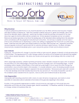
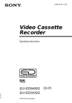
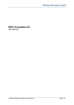
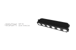
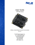
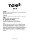
K-DT1 Portable Radar Doppler Target
User Manual
© RFbeam Microwave GmbH www.rfbeam.ch
Page 1/9
User Manual
K-DT1 DopplerTarget
Features
•
•
•
•
•
•
•
•
•
•
Handheld K-Band Doppler Target Simulator
Battery Operation
Programmable Speed Range 1 ... 200km/h
Programmable Movement Direction
Programmable Signal Time
3 Programmable Presets
Standalone or Hosted Operation
USB Interface to Hostcomputer
Compact and Rugged Construction
DT1-Remote PC Software included
Applications
•
•
•
•
Mobile Test Equipments
Production Final Inspection
Incoming Components Inspection
System Tuning and Adjustment
Overview
K-DT1 is a portable moving target simulator for
K-band Radar transceivers. It can be used for
calibrating and testing speed displays, door
openers, safety systems and other radar based
Doppler sensors. K-DT1 uses a circular
polarized antenna. You can use K-DT1 in any
orientation independently of the sensor
orientation.
A software generated modulation signal allows
generation of low distortion and directional
Doppler
signals
from
44Hz
to
9kHz
corresponding to speeds from 1km/h to 200km/h.
Getting Started
This chapter explains the first steps of using the K-DT1 device and the DT1-Remote Software.
Equipment Needed
●
●
●
●
●
RFbeam K-DT1 Device
Four Size AA Batteries
RFbeam USB Stick with DT1-Remote Software
PC with Windows 2000/xp/vista
Optionally an RFbeam ST100 Starterkit
DT1-Remote Software
K-DT1 may be connected via USB to any Windows PC. The included DT1-Remote software allows
realtime remote controlling and configuring the presets of the K-DT1.
© 2009 RFbeam Microwave GmbH www.rfbeam.ch
Page 2/9
K-DT1 DopplerTarget
User Manual
Installing from USB Stick
1. Remove any K-DT1 system connected to your system
2. Insert RFbeam USB memory stick and start setup.exe.
If your computer does not already contain the actual LabVIEW runtime engine, you will be asked
to accept licences of National Instruments.
3. If possible, accept all default program locations. Troubleshooting will be simplified like this.
4. Please be patient while LabVIEW runtime system is being installed.
5. You will find DT1-Remote under START-PROGRAMS-RFbeam-DT1 Remote
6. Plug your K-DT1 system to a USB port of your PC. There should appear a “New USB Hardware
Found” message from Windows.
7. Windows will ask you for a hardware driver. Select to install it manually and chose the drive letter
of the USB stick. Ignore the Windows logo test message.
8. Start DT1-Remote Software.
As soon as K-DT1 system has been connected, the search LED stops flashing and DT1-Remote
software is ready.
If K-DT1 will not be found, please reinstall the hardware driver and try again. (See chapter FAQ
for more details).
DT1-Remote Screen
After launching the DT1-Remote Software, the screen below should appear.
Fig. 1: K-DT1 Screen
See chapter DT1-Remote Software for details on this software.
© 2009 RFbeam Microwave GmbH www.rfbeam.ch
Page 3/9
User Manual
K-DT1 DopplerTarget
K-DT1 Handheld Operation
Controls
(1) USB Connector
(4) Power Indicator
(5) Active Preset
(2) Preset Selector
(6) Antenna
(3) Power On
Fig. 2: Controls and Displays
Using K-DT1
General Remarks
Prepare the settings as described in section Configuring K-DT1
Maximum distance depends on the radar sensitivity and the amplitude settings of K-DT1.
Using Default Preset
The default preset will be executed, until the programmed duration elapses.
1. Align the antenna (6) against the transceiver
2. Press the Power switch (3) for 0.5 seconds
> K-DT1 begins simulating the programmed speed, amplitude and direction
> K-DT1 stops after the programmed duration or after switching off manually with (3)
Selecting Another Preset
The selected preset will become the new default preset and will be executed, until the programmed
duration elapses:
1. Press Power switch (3) while pressing the Preset selector (2)
> K-DT1 default preset LED (5) blinks
2. Repeat pressing the Preset selector (2) until the desired preset LED (5) flashes
> after 1 second, the selected LED (5) stops blinking and K-DT1 runs the selected preset
> the selected preset will become the new default preset
Playing Around
If you own an RFbeam Starterkit (http://www.rfbeam.com/81.0.html), you may test all the K-DT1
features by running the ST100 SignalViewer with a K-LC1 or even better a K-LC2 sensor.
© 2009 RFbeam Microwave GmbH www.rfbeam.ch
Page 4/9
User Manual
K-DT1 DopplerTarget
DT1-Remote Software
Legend of Controls
(1) Doppler Signal ON/OFF
(2) Direction of Movement
5
1
(3) Doppler Amplitude (simulates
object distance)
8
2
3
(4) Object Speed parallel to (5)
6
(5) Object Speed parallel to (4)
4
7
9
10
(6) Select Speed Display Unit
(7) Copy Settings to Preset Memory
(8) Select Standard Preset
Fig. 3: DT1-Remote Software Screen
(9) Duration of Doppler Signal
(10) Save Presets to K-DT1
This software allows real time control and configuring the K-DT1 target. You can get help by moving
the mouse over the control elements. Menu „Help-Show Context Help“ opens a small window with
additional information.
Remote Controlling K-DT1
K-DT1 may be remotely controlled by the DT1-Remote software. The realtime remote control part is
called Live Setting on the left half of the Software panel. Please connect K-DT1 to a USB port before
changing any controls.
Switching ON/OFF
Click [Target ON] key (1) to toggle speed simulation on and off. Shortcut key [F2].
Setting Speed
Speed setting may be controlled by different methods:
- Move needle (5)
- Type value or use spin controls in (4)
- Use [PageUp] and [PageDown] keys on PC keyboard
- Shortcut key: [F4], then cursor up/down
Setting Movement Direction
Toggle the direction with control (3). This control changes the sign of the 90° phase shift between the
I and Q channel.
Note: Direction is only detectable by „stereo“ sensors like K-LC2, K-MC1, K-MC2 etc.
Setting Signal Amplitude
Simulate object distances by adjusting the signal amplitude (3).
This may be useful for testing system sensitivity. Please note, that a 100% amplitude produces not a
big Doppler signal at the sensor system:
In 1m distance, you get approximately:
200mVpp at the “High Gain Output” of K-MC1
120uVpp at the output of a K-LC1
60uVpp at the output of a K-LC2
© 2009 RFbeam Microwave GmbH www.rfbeam.ch
Page 5/9
K-DT1 DopplerTarget
User Manual
Configuring K-DT1
K-DT1 starts up with a “default preset”. This is one of three configurable presets. All presets can be
configured by means of the DT1-Remote software or with a terminal software.
Default preset can also be selected manually directly with the K-DT1. See chapter Selecting Another
Preset.
Storing Settings as Presets
1. Select the desired parameters in the Live Setting section with controls (1) to (6)
2. Copy these parameters to the desired preset with selector (7)
3. Save presets with control (10)
Set Signal Duration
K-DT1 sends a Doppler signal, until signal duration has elapsed and then switches off.
1. For each preset, you may select an individual duration with control (9).
Value range is 0.1 to 60sec. Value 0 means 'unlimited' (switches off after 3 minutes timeout for
battery saving).
2. Save presets with control (10)
Set Default Preset
Default preset will be active after normal power on of the K-DT1. It may later be altered directly at the
K-DT1.
1. Select default preset with (8)
2. Save presets with control (10)
Getting Help
Get help by selectig Menu-Help.
Get tips by moving cursor over the controls.
K-DT1 USB Serial Interface
K-DT1 can optionally be operated by a terminal program or by customer software.
The USB port is represented as serial interface by the driver software, that has been installed
according to chapter Installing from USB Stick.
1. Connect K-DT1
2. Start DT1-Remote software or check the windows control panel to get the assigned COM port.
Close DT1-Remorte software before opening terminal software!
3. Open a terminal program like Windows Hyper Terminal
4. Select the appropriate COM port. All other settings are not used.
5. Press [Enter]. Now, the following screen (Fig. 4) should appear:
© 2009 RFbeam Microwave GmbH www.rfbeam.ch
Page 6/9
User Manual
K-DT1 DopplerTarget
Terminal Mode: Remote Control
RFbeam K-DT1 24GHz Doppler Target #09200100
==============================================
Program Version V1.00 Aug 21 2009
Default Preset
:
[d]
[s]
[r]
[t]
:
0
:
3
: 100
:
1
Direction of Motion
Speed
Reach
Target On/Off
1
[0=none, 1..3=Preset]
[0=Forward, 1=Backward]
[001..200km/h]
[001..100%]
[0=Off, 1=On]
[p] Presets Setup
[x] Back to manual mode
->
Fig. 4: K-DT1 Terminal Remote Control Dialog
These settings are directly executed, as long as K-DT1 remains connected to the USB port.
With [p], you will be able to configure the preset memory.
Terminal Mode: Preset Setting
For using presets please refer to chapter Using K-DT1.
Presets Setup Page
==================
[q]
[w]
[e]
[r]
P1
P1
P1
P1
Direction of Motion
Speed
Reach
Time
:
:
:
:
0
3
100
0
[0=Forward, 1=Backward]
[001..200km/h]
[001..100%]
[001..600x100ms, 0=endless]
[t]
[z]
[u]
[i]
P2
P2
P2
P2
Direction of Motion
Speed
Reach
Time
:
:
:
:
0
113
100
60
[0=Forward, 1=Backward]
[001..200km/h]
[001..100%]
[001..600x100ms, 0=endless]
[o]
[p]
[a]
[s]
P3
P3
P3
P3
Direction of Motion
Speed
Reach
Time
:
:
:
:
0
9
100
10
[0=Forward, 1=Backward]
[001..200km/h]
[001..100%]
[001..600x100ms, 0=endless]
[c] Default Preset
:
[l] Save and Leave Preset Setup
1
[0=none, 1..3=Preset]
->
Fig. 5: K-DT1 Preset Terminal Dialog
Refer to chapter Configuring K-DT1 for parameter explanations.
© 2009 RFbeam Microwave GmbH www.rfbeam.ch
Page 7/9
User Manual
K-DT1 DopplerTarget
Characteristics
Parameter
Conditions / Notes
Symbol
Min
Typ
Max
Unit
Battery
USB
VccBatt
3.6
6
7
V
VccUSB
4.5
5
5.5
Operating
Icc
340
V
mA
Standby
Icc0
50
uA
Battery Lifetime
Daily use 50 seconds, Alcaline cells
Top
1
Year
Operating temperature
non condensing
Top
0
+60
°C
Tst
-20
+80
°C
Operating conditions
Supply voltage
Supply current
Storage temperature
Doppler Simulator
Frequency range
Transmit frequency of UUT
fTG
24.000
24.250
Doppler frequency range
Digitally adjustable
fDoppler
44
8800
Hz
Simulated speed range
Digitally adjustable
vDoppler
1
200
km/h
Output power range
Adjustable simulated object distance
Pout
1
100
%
Antenna gain
Antenna polarization
Overall gain
14
Right hand circular polarized
dBi
RHCP
For circular polarized tranceivers
38
For linear polarized tranceivers
32
Out of band spurious
Aequivalent reflectivity
GHz
dB
dB
-30
dBm
For circular polarized tranceivers
RCScirc
800
cm2
For linear polarized tranceivers
RCSlin
200
cm2
68x128x24
mm3
Host Interface
USB
Serial USB, Mini-USB connector
Body
Outline Dimensions
Weight
Including batteries
185
g
Accessories
Case protection, Softcase, USB Cable, USB Memory Stick, 4 AA-size Alkaline Cells, Windows Software “DT-1 Remote”
Ordering Information
Part #: RFbeam K-DT1
© 2009 RFbeam Microwave GmbH www.rfbeam.ch
Page 8/9
K-DT1 DopplerTarget
User Manual
FAQ
Q:
A:
Why does K-DT1 not connect to the DT1-Remote software?
Please try the following:
• Close DT1-Remote software and disconnect-reconnect K-DT1. Restart the software.
• Close DT1-Remote software and connect K-DT1 to an other USB port.
• Reinstall the driver file 'RFbeam_K-DT1.inf'. This file resides on the installation media and
also in the program file directory.
Q:
A:
What is the usable distance range?
This depends on your radar system. For traffic speed displays, a typical range will be around 3
to 5 meters.
Q:
A:
Why do I get different output amplitudes at the same radar transceiver?
For precision sensitivity tests, K-DT1 and also the unit under test (UUT) should be
mechanically fixed.
You should also prevent objects nearby the direct link between K-DT1 and the UUT.
Use distances >=30cm between K-DT1 and the UUT.
Use absorber material (e.g. Ecosorb AN or Ecosorb LS from Emerson&Cuming) , if the testsetting is placed on a table or in a test chamber.
A:
What is the expected battery life?
With a daily use of 50 seconds, Alkaline cells should last about 1 year.
Q:
A:
Is battery loaded while K-DT1 is connected on USB port?
No. K-DT1 is powered by the USB port during a host connection.
Q:
A:
How can I measure frequency and RF power of my transceivers?
K-DT1 is only a Doppler Simulator. For power and frequency mesurements, you may use the
RFbeam K-TS1 system.
User Manual Revision History
Version
1.0
1.1
Date
15-Sept 2009
15-Oct 2009
Changes
initial release
corrected chapter Selecting Another Preset
RFbeam does not assume any responsibility for use of any circuitry described, no circuit patent licenses are implied and
RFbeam reserves the right at any time without notice to change said circuitry and specifications.
© 2009 RFbeam Microwave GmbH www.rfbeam.ch
Page 9/9