1
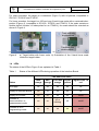
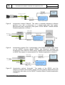
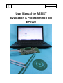
User Manual for ASSIST Evaluation & Programming Tool
EPT002 V2B
Page 1 of 52
User Manual for ASSIST
Evaluation & Programming Tool
EPT002
User Manual for ASSIST Evaluation & Programming Tool
EPT002 V2B
Page 2 of 52
CONTENTS
1. Hardware ....................................................................................................................... 3
1.1 Contents................................................................................................................ 3
1.2 Interface Board ..................................................................................................... 4
1.3 Targets: codewheels and linear scales ................................................................. 4
1.4 LEDs ..................................................................................................................... 5
2. Operation without PC .................................................................................................... 6
3. Software installation ...................................................................................................... 7
3.1 Installation on a PC with LabViewTM ..................................................................... 7
3.2 Installation on a PC without LabView .................................................................... 8
4. ASSIST software user guide ......................................................................................... 9
4.1 Configuration......................................................................................................... 9
4.1.1 Measurement configuration ...................................................................... 10
4.1.2 Encoder configuration............................................................................... 10
4.1.2.1 Interpolation ............................................................................... 10
4.1.2.2 LookUp Table ............................................................................ 11
4.1.2.3 Encoder ID ................................................................................. 11
4.2 Evaluation ........................................................................................................... 11
4.3 Linearization........................................................................................................ 12
4.4 Debug ................................................................................................................. 15
4.4.1 Interface Board Firmware ......................................................................... 15
4.4.2 Interface Board Supply Voltage ................................................................ 15
4.4.3 Encoder connection test ........................................................................... 15
4.4.4 Encoder supply test .................................................................................. 16
4.5 Encoder operating modes ................................................................................... 16
4.6 Encoder RAM and OTP memories ...................................................................... 17
4.7 Encoder status .................................................................................................... 17
4.8 Operate encoder with Default LUT or LUT from file or OTP................................ 18
4.9 Measure linearity with Default LUT or LUT from file or OTP ............................... 19
4.10 Program a LUT directly into OTP ........................................................................ 21
4.11 Export linearity measurement data to spreadsheet ............................................. 21
4.12 Adapting scales and line properties in graphs..................................................... 22
4.13 LUT file format .................................................................................................... 23
4.14 Result file format ................................................................................................. 25
Annex 1 Manual linearization ............................................................................................ 26
Annex 2 Linearization with external DAQ system.............................................................. 31
Annex 3 Automatic linearization ........................................................................................ 36
Annex 4 Linearization of a rotary encoder......................................................................... 41
Annex 5 Schematics ......................................................................................................... 42
Annex 6 Electrical connections POSIC- and Reference-encoders .................................... 44
Annex 7 Troubleshooting .................................................................................................. 47
Annex 8 Glossary .............................................................................................................. 51
User Manual for ASSIST Evaluation & Programming Tool
EPT002 V2B
Page 3 of 52
1. Hardware
1.1 Contents
The contents of the Evaluation and Programming Tool EPT002 is shown in Figure 1.
Interface Board
2 Encoders
USB cable
USB cable
Enclosure
Target
Holder
Codewheel
or
Linear Scale
Interface Board
Figure 1
Evaluation and Programming Tool EPT002 (left) and the Programming Tool
PT002 (right).
The Evaluation and Programming Tool EPT002 is intended for “new customers”. It allows:
- basic evaluation and demonstration (without a PC)
- detailed evaluation and linearization using the ASSIST software on a PC
- programming of the encoder’s volatile and non-volatile memories
The Programming Tool PT002 is intended for customers who already have POSIC
encoders and only need the Interface Board and its enclosure. The Programming Tool
PT002 has the exact same functionality as the Evaluation and Programming Tool EPT002,
but does not include the evaluation-encoders nor a target.
User Manual for ASSIST Evaluation & Programming Tool
EPT002 V2B
Page 4 of 52
1.2 Interface Board
The most important elements on the Interface Board are shown in Figure 2. The
schematics are given in Annex 5.
DIP switches
POSIC
Encoder
Signal LEDs
Reference
Encoder
Power LED “PWR”
Encoder LED “ENC”
USB
System LED “SYSTEM”
OTP Prog LED “PROG”
Start/Stop button
Reset button
Scale
RS422 Receiver
Terminal block
Signal TestPins “TP”
Microcontroller
Ground connection
Target-holder
Figure 2
The Interface Board.
1.3 Targets: codewheels and linear scales
The Interface Board contains a target-holder, which holds the target and the encoder in the
correct position with respect to each other.
Target-holder
Figure 3
Target-holder with codewheel.
Codewheel
EPT002 V2B
User Manual for ASSIST Evaluation & Programming Tool
Page 5 of 52
For rotary encoders, the target is a codewheel (Figure 3) with 64 periods, compatible to
ID1101C, ID1301C and IT3401C.
For linear encoders, the target is a 100 mm long 2-track linear scale with a centered indexpositon (Figure 4), compatible to ID1101L, ID1301L and IT3401L. If the scale contains a
double period (location of Index-pulse for an IT3401L), the scale should be oriented as
shown in Figure 4.
Track with only
single periods
a)
Target-holder
Figure 4
Linear Scale
Track with one
double period
b)
a) Target-holder with linear scale. b) Orientation of the 2-track linear scale
inside the target-holder.
1.4 LEDs
The status of the LEDs in Figure 2 are explained in Table 1.
Table 1
Status of the different LEDs during operation of the Interface Board.
LED name and color
PWR
orange
ENC
orange
SYSTEM
orange
PROG
yellow
Signal LEDs 1-8
red
No supply
off
off
off
off
off
Supply to Interface Board
on
off
off
off
off
Supply to Encoder
on
on
off
off
on/off
Encoder in
communication- or
measurement-mode
on
on
off or
blinking
off
on/off
Encoder in OTP
programming mode
on
on
on
on
on/off
Status
User Manual for ASSIST Evaluation & Programming Tool
EPT002 V2B
Page 6 of 52
2. Operation without PC
For basic evaluation and demonstration purposes, the Interface Board can be operated
without a PC. The operation without PC is described in the sequence below and is
illustrated in Figure 5.
Encoder signals
Figure 5
PWR
ENC
Start/Stop button
Operation of the Interface Board without PC.
Operation without PC:
1) Connect the Interface Board to a USB power-source (not a PC). The LED “PWR”
will light up.
2) Press the “start/stop” button on the Interface Board. The encoder is activated and
the LED “ENC” lights up. The encoder is now active and the Signal LEDs show the
encoder signals.
3) Place the encoder in front of the target and move the target gently. The A quad B
encoder output signals are displayed by the Signal LEDs and can be measured on
the Signal TestPins (see also Figure 2)
4) Press the “start/stop” button again. The encoder is stopped (LED “ENC” turns off
and Signal LEDs turn off). The encoder and/or the USB power-supply may now be
unplugged.
User Manual for ASSIST Evaluation & Programming Tool
EPT002 V2B
Page 7 of 52
3. Software installation
The ASSIST software has been developed for operation on a PC with a MicroSoft
WindowsTM XP, 7 or 8 operating system.
The ASSIST Software is either provided on a USB-key or can be downloaded from the
POSIC website. Access to the download page is granted upon purchase of the Evaluation
and Programming Tool EPT002.
If LabView™ is installed on your PC or if a previous version of ASSIST has been installed,
please carry out the installation according to Section 3.1.
If LabView™ is not installed on your PC and if ASSIST has not been installed previously,
please carry out the installation according to Section 3.2.
3.1 Installation on a PC with LabViewTM
This installation should be carried out if LabViewTM is installed on your PC or if a previous
version of ASSIST has been installed on your PC.
ASSIST Installation
1) Download and unzip ASSIST_Vx.x.x.zip
2) Copy the directory ASSIST_Vx.x.x to the
desired location in your PC. It is not
necessary to carry out an installation or to reboot your PC.
3) In the directory ASSIST_Vx.x.x launch the
application Posic.exe (it is recommended to create a shortcut on your desktop)
Vx.x.x designates the version of the ASSIST software and may for example be: V0.0.4
USB Driver
1) Download and unzip the file driver.zip
2) Connect the Interface Board via the USBcable to your PC. A USB-driver installation
wizard will appear.
3) Use the browser of the installation wizard to
select “mchpcdc”,the wizard will carry out the
installation.
User Manual for ASSIST Evaluation & Programming Tool
EPT002 V2B
Page 8 of 52
3.2 Installation on a PC without LabView
This installation should be carried out if LabViewTM is not installed on your PC and ASSIST
has not been installed on your PC previously.
LabViewTM Runtime
The ASSIST Software is written in LabView™. LabView™ Runtime is required to execute
the ASSIST software. LabView™ Runtime is about 250 MB, downloading may take up to
several minutes and installation may take up to several tens of minutes.
ASSIST installation including LabViewTM Runtime
1) Download and unzip ASSIST_Vx.x.x.zip
2) Go to \ASSIST_Vx.x.x_Install\Volume\
3) Launch “setup.exe”, a wizard installs ASSIST
4) Go to the directory \ASSIST_Vx.x.x\
5) “Posic.exe” starts the ASSIST software
Vx.x.x designates the version of the ASSIST software and may for example be: V0.0.4
USB Driver
1) Connect the Interface Board via the USBcable to your PC. A USB-driver installation
wizard will appear.
2) Use the browser of the installation wizard to
select “mchpcdc”,the wizard will carry out the
installation.
User Manual for ASSIST Evaluation & Programming Tool
EPT002 V2B
Page 9 of 52
4. ASSIST software user guide
The ASSIST software consists of four windows that can be selected by means of four tabs
as shown in Figure 6.
Figure 6
Four tabs to select one of the four windows Configuration, Evaluation,
Linearization or Debug.
4.1 Configuration
ASSIST starts up in the Configuration window. Initially an hourglass will be visible, during
which the USB-connection with the Interface Board is established. Depending on the
number of USB-ports and their use, it may take several (tens of) seconds to establish the
USB-connection. As long as the USB-connection has not been established, the ASSIST
software remains inactive.
Figure 7
Configuration window.
EPT002 V2B
User Manual for ASSIST Evaluation & Programming Tool
Page 10 of 52
The top-half of the configuration window defines the measurement configuration (Section
4.1.1), whereas the lower part defines the POSIC-encoder configuration (Section 4.1.2).
4.1.1
Measurement configuration
1) Select whether the system is linear
or rotary.
2) Define the target of the POSIC
encoder. Linear: scale period length
(1.2
or
1.28
mm).
Rotary:
codewheel number of periods
(standard codewheel: 64).
1
2
3
3) Define resolution of the Reference
encoder. Linear: step size (e.g 0.1
um). Rotary: increments / revolution
(e.g. 16’384 incr/rev if the encoder
resolution is 14 bits = 4’096 CPR).
4.1.2
Encoder configuration
When the ASSIST software is started and each time a new encoder is connected, the
Read Encoder Configuration button
must be pressed, so that
ASSIST reads the encoder configuration stored in the encoder’s OTP memory.
4.1.2.1
Interpolation
The interpolation factor
is expressed in bits per period and in
cycles per period (CPP). Table 2 explains the relation between the interpolation factor and
the resolution for certain cases. The interpolation factors that are possible for a given
encoder can be selected from a pulldown menu. Typically the interpolation factor can be
set to either 3 – 8 bits or 10 – 12 bits.
User Manual for ASSIST Evaluation & Programming Tool
Table 2
EPT002 V2B
Page 11 of 52
Resolution for a given target as a function of the adjusted interpolation value.
Interpolation value
Resolution depending on target (codewheel/scale)
Bits
Increments
Per Period
Cycles
Per
Period
Resolution
linear scale
1.2 mm period
Resolution
linear scale
1.28 mm period
Resolution
codewheel
64 periods
3
23 = 8
2
150 um
160 um
128 CPR
4
24 = 16
4
75 um
80 um
256 CPR
5
25 = 32
8
37.5 um
40 um
512 CPR
6
26 = 64
16
18.75 um
20 um
1’024 CPR
7
27 = 128
32
9.375 um
10 um
2’048 CPR
8
28 = 256
64
4.6875 um
5 um
4’096 CPR
10
210 = 1024
256
1.171875 um
1.25 um
16’384 CPR
11
211 = 2048
512
0.5859375 um
0.625 um
32’768 CPR
12
212 = 4096
1024
0.29296875 um
0.3125 um
65’538 CPR
One A quad B cycle consists of 4 increments.
The linear resolution is typically expressed as the length of one increment.
The rotary resolution is typically expressed as the number of A quad B Cycles Per
Revolution (CPR).
4.1.2.2
LookUp Table
The encoder contains a LookUp Table (LUT) that can be used to correct the
encoder’s non-linearities. One of three options can be selected:
- Default: Default LUT-file stored in the ASSIST software. This LUT is a
general-purpose LUT and does not compensate non-linearities of a specific target.
- File: file selected using a browser. This could e.g. be a “typical LUT” for a specific
target or the LUT previously generated in the Linearization window
- OTP: the LUT stored in the encoder’s OTP memory will be used.
4.1.2.3
Encoder ID
The Encoder Identification number consists of three 16-bit numbers.
Each number can be programmed to a value between 0 and 65535.
The encoder ID has no influence on the encoder operation.
4.2 Evaluation
The evaluation window allows you to:
- check whether the POSIC- and Reference-encoder are working correctly
- operate the POSIC- (and Reference-) encoder in a closed-loop control system by
using POSIC encoder signals available on the Interface Board.
User Manual for ASSIST Evaluation & Programming Tool
1) The reference encoder (if available)
can be activated by pressing the
ON/OFF button prior to starting the
POSIC encoder.
2
EPT002 V2B
Page 12 of 52
1
2) The POSIC encoder can be started
and stopped by pressing the
Start/Stop button.
3) The graph displays the POSIC
encoder position (white) and the
Reference encoder position (white)
as a function of time.
3
The vertical scale in the Evaluation window is automatically adjusted to one period-length.
In the example above, a codewheel with 64 periods is used, each period corresponds to
360°/64 = 5.625°.
4.3 Linearization
Table 3 and Figure 8 until Figure 10 provide an overview of the three linearizationmethods, which are explained in detail in Annex 1 until Annex 3. The Automatic
linearization method is the most efficient one, because it does not require manual
adjustment (method Manual) and does not require the preparation and transfer of a
measurement file (method File).
Table 3
Linearization methods.
Linearization Measurement
method
reference
Scale
movement
Data Acquisition
system
Information
Manual
Microscrew
or caliper
Manual with
fixed precise
steps
ASSIST Interface
Board
Figure 8
Annex 1
File
Reference
encoder
Motorized or
manual
External DAQ system
with two A quad B +
Index interfaces
Figure 9
Annex 2
Automatic
Reference
encoder
Motorized or
manual
ASSIST Interface
Board
Figure 10
Annex 3
EPT002 V2B
User Manual for ASSIST Evaluation & Programming Tool
Page 13 of 52
Meas. data
ASSIST
Software
Config + LUT
Movement of scale
Position (mm)
0.000
USB
POSIC
Encoder
Reference Encoder
Meas. data
POSIC Encoder
Config + LUT
Figure 8
ASSIST Interface Board
Linearization method “Manual”. The scale is manually adjusted to different
positions (e.g. with a microscrew or a stepper-motor with fixed steps).
Measurement and configuration take place via the ASSIST Interface Board.
Detailed explanation in Annex 1.
Meas. data
Movement
Reference
Encoder
Config + LUT
Meas. data
of scales
Data
Acquisition
(DAQ) System
USB
POSIC
Encoder
Reference Encoder
Meas.
file
POSIC Encoder
Config + LUT
Figure 9
ASSIST Interface Board
Linearization method “File”. Configuration of the POSIC encoder takes place
via the ASSIST Interface Board. POSIC- and Reference encoders are
measured by the customer’s DAQ system. Measurement data are transferred
to ASSIST by means of a measurement file. Detailed explanation in Annex 2.
Meas. data
Movement
ASSIST
Software
Meas. data
ASSIST
Software
Reference
Encoder
Config + LUT
of scales
USB
POSIC
Encoder
Meas. data
Reference Encoder
POSIC Encoder
Config + LUT
Figure 10
ASSIST Interface Board
Linearization method “Automatic”. The scales of the POSIC- and the
reference-encoders are moved by means of a drive system. Measurement and
configuration take place via the ASSIST Interface Board. Detailed explanation
in Annex 3.
Recommendations for linearization
User Manual for ASSIST Evaluation & Programming Tool
EPT002 V2B
Page 14 of 52
-
Minimum range The absolute minimum range is one scale-period. It is
recommended to linearize over multiple periods, the LUT will be calculated using
the average values, thus reducing the influence of noise or target errors. For a
linear application it is recommended to linearize over the complete range or at least
over the range where the highest linearity is required. For a rotary application it is
recommended to linearize over one full rotation (in order to take into account a
potential runout)
-
Maximum range For a linear application: length of scale with a margin of 2 complete
scale-periods at each end of the scale. For a rotary application: one complete
rotation of the codewheel
-
Direction of movement During the linearization, the target must move in only one
direction with respect to the encoder. This is a precaution to avoid potential
problems with the hysteresis of the reference encoder. Changes in direction during
the calibration are not allowed
-
Maximum speed It is recommended to stay at least a factor 10 below the maximum
speed (lowest of the reference- and POSIC-encoder) in order to avoid effects due to
bandwidth limitations. For the method “automatic”, the maximum speed is given in
Annex 3.
-
Number of calibration-points It is recommended to use at least 20 calibration-points
per target-period. For the manual linearization method with a linear scale, this
corresponds to a step size of approximately 0.05 mm. The LUT is calculated using
an 8th-order polynomial fitting-procedure: additional calibration points above 20 will
not significantly improve the resulting LUT.
-
Spacing between calibration points For optimum linearization, it is recommended to
use equidistant calibration points (e.g. 1.2 mm / 24 points = 0.05 mm between two
calibration points). However, non-equidistant calibration points are acceptable as
long as the maximum distance between two calibration points does not exceed the
period length/20 (see previous point on the number of calibration points). Nonequidistant calibration points may occur due to non-constant speed of a linear
actuator or due to non-constant readout-frequency of the reference- and POSICencoders. It is not required that the period length is an integer multiple of the
calibration point spacing. Example: the combination of period length = 1.2 mm and
calibration point spacing = 0.018 mm would be perfectly OK, although their ratio is
not an integer number: 66.67.
-
Linearity of reference encoder The result of the linearization will by definition not be
better than the linearity of the reference encoder. It is recommended to use a
reference encoder with a linearity that is at least 10 times higher than the desired
linearity of the POSIC encoder after linearization.
User Manual for ASSIST Evaluation & Programming Tool
EPT002 V2B
Page 15 of 52
4.4 Debug
The Debug window is shown in Figure 11 and allows you to check whether the
InterfaceBoard and the encoder are working correctly.
Figure 11
4.4.1
The Debug window.
Interface Board Firmware
The Interface Board Firmware is the firmware in the dsPIC microcontroller (see Figure 2).
4.4.2
Interface Board Supply Voltage
The Interface Board receives a 5V USB supply voltage. The USB supply voltage is
boosted to the Interface Board Supply Voltage with a level between 7.5 and 9 V (Annex 5).
The Interface Board Supply Voltage is measured when the board is powered-up (it is not
continuously measured) and displayed in the Debug window.
4.4.3
Encoder connection test
The encoder connection test allows you to check whether all electrical connections (supply
and outputs) are correct. The test is activated by pressing the “Start Test” button and
stopped by pressing the “Stop Test” button.
When the electric test is active, the outputs toggle on and off with a frequency around 1
Hz. This can be observed on the signal LEDs on the interface Board (Figure 2 in Section
1.2). If the LEDs are not toggling correctly, see Annex 7 on Troubleshooting.
LEDs that are not connected to the encoder’s outputs are continuously on (emitting light)
during this test.
User Manual for ASSIST Evaluation & Programming Tool
4.4.4
EPT002 V2B
Page 16 of 52
Encoder supply test
The encoder supply test allows you to check whether the encoder supply voltage and
current are correct. The test is activated by pressing the “Start Test” and stopped by
pressing the “Stop Test” button.
During this test, the encoder is activated, its output signals can be observed/measured on
the Interface Board and the supply voltage and current are measured continuously and
displayed at the top right side of the window.
4.5 Encoder operating modes
The 4 modes in which the encoder can be operated using ASSIST are listed in Table 4.
Table 4
Operating modes of the encoder.
Mode
Description
In/outputs
Communication
mode
2-wire serial communication to read data
from the encoder and to store configuration
data and LUT in the encoder’s RAM (volatile
memory)
A = clock (input)
B = data (bidirectional)
Measurement
mode
Encoder measures incremental position and
outputs via ABI interface
A, B, I incremental
encoder output signals
Programming
mode
2-wire serial communication to program
configuration data and LUT in OTP (One
Time Programmable non-volatile memory)
A = clock (input)
B = data (bidirectional)
Connection test
mode
All outputs toggle on/off
A, B, I toggle on/off
(all outputs)
The communication mode is employed in the following cases:
- Configuration Window, Read Encoder Configuration (read data from encoder)
- Evaluation Window, Start (send configuration data and LUT to encoder)
- Linearization Window, Measure Default LUT and Measure RAM LUT (send
configuration data and LUT to encoder)
The measurement mode is employed in the following cases:
- Evaluation Window, Start (after encoder has been configured)
- Linearization Window, Measure Default LUT and Measure RAM LUT (after encoder
has been configured)
- Debug window, Encoder supply test
The programming mode is employed in the following cases:
- Configuration window, “Program in OTP” of the interpolation factor, the LUT or the
EncoderID
- Linearization window, “Program LUT in OTP”
The connection test mode is employed in the following cases:
- Debug window, encoder connection test
EPT002 V2B
User Manual for ASSIST Evaluation & Programming Tool
Page 17 of 52
4.6 Encoder RAM and OTP memories
The encoder’s configuration data and LUT can be stored in RAM (Random Access
Memory). The RAM is volatile: any data written into the encoder’s RAM will be lost when
the encoder-power is turned off.
The encoder’s configuration data and LUT can be stored in OTP memory (One Time
Programmable). The OTP memory is non-volatile: any data programmed into the
encoder’s OTP memory is permanently stored and cannot be re-programmed or erased.
Therefore each OTP programming sequence is preceded by a dialog-box with a warning
that OTP programming is irreversible and asking a confirmation to continue.
When the encoder is operated using ASSIST, it is always operated using RAM data (the
contents of OTP memory is ignored).
When the encoder is operated without ASSIST, it is always operated using OTP data.
Non-programmed OTP memory contains all ones. A non-programmed 16-bit number has
therefore the hexadecimal value FFFF = decimal value 216 -1 = 65’535 (see Encoder ID,
Figure 7).
4.7 Encoder status
At the top right side of each window, the encoder status is displayed (see Figure 12):
- Indicator showing whether the encoder is on or off.
- Encoder supply voltage (VDD)
- Encoder supply current (IDD)
The supply voltage and current are measured when the encoder is started up and when it
goes from one operating mode to another (e.g. from communication mode to
measurement mode).
When the encoder indicator is off, the encoder can be disconnected (replaced by another
encoder). While the indicator is on, the encoder should not be disconnected.
a)
Figure 12
b)
c)
d)
e)
Zoom-in of the top right side of all ASSIST windows showing the supply status
of the encoder. a) Encoder has not been activated yet. b) Encoder has been
activated, but is not powered at this moment. c) Encoder is working. d) OTP
Programming ongoing. e) Short-circuit detected, encoder has been turned off.
The typical supply voltage and current levels are listed in Table 5.
User Manual for ASSIST Evaluation & Programming Tool
Table 5
EPT002 V2B
Page 18 of 52
Encoder supply voltage and current levels in different operation modes.
Current IDD is measured with no load on the encoder outputs.
Mode
VDD
IDD
Communication
5V
< 10 mA
Measurement
5V
OTP Programming
Short circuit*
Comment
10 – 15 mA
ID1101, ID1301
20 – 30 mA
IT3401
6 - 6.5 V
< 10 mA
<5V
> 50 mA
Encoder automatically turned off**
* When the current measured during startup of the encoder is well above the typical level,
it is assumed that a short-circuit has occurred between supply and ground or between an
output and ground. In this case, the supply to the encoder is cut off and the IDD indicator
turns red. The short-circuit should be eliminated before turning the encoder on again.
**When the Interface Board is connected to a low-power USB connection (typically on a
USB-hub or at the side of a PC-screen with current limited to 100 mA), the current drawn
during the short-circuit may exceed the maximum current of the USB-connection and
supply to the Interface Board may be cut off. In that case, the ASSIST software may be
halted before it signals the short-circuit. If this happens, disconnect the Interface Board
from the PC and close the ASSIST software. Eliminate the short-circuit, re-connect the
Interface Board and re-start the ASSIST software.
4.8 Operate encoder with Default LUT or LUT from file or OTP
This mode of operation is useful if the encoder has already been linearized and has to be
operated e.g. in a closed-loop system with a controller. Please make sure that the POSICand the Reference-encoder have been correctly configured prior to launching the
procedure explained below.
1) Select the appropriate LookUp
Table: Default, File or OTP.
2) If “File” is selected, use the browser
to select the LUT file.
The selected LUT will be uploaded
in the RAM LUT.
1
2
User Manual for ASSIST Evaluation & Programming Tool
EPT002 V2B
Page 19 of 52
3) If desired, turn on the reference
encoder.
4) Start the POSIC encoder.
4
The POSIC and reference encoder
remain working until the POSIC
encoder is stopped. During
operation, the results are
continuously displayed in the graph
and the encoder output signals can
be measured on the Interface
Board.
3
After step 4, ou can connect the A, B and I outputs of the encoder to another system (a
counter, a controller or other equipment) using the Signal Test Pins or the Terminal Block,
see Figure 2.
4.9 Measure linearity with Default LUT or LUT from file or OTP
This mode of operation is useful if the linearity of the encoder has to be measured
repeatedly or if a “general purpose” LUT has to be tested with several encoders.
Prior to executing the steps in the table below, please make sure that the POSIC encoder
(and the reference encoder if applicable) has been configured correctly in the configuration
window (Section 4.1).
1) Select the appropriate LookUp
Table: Default, File or OTP.
2) If “File” is selected, use the browser
to select the LUT file.
The selected LUT will be uploaded
in the RAM LUT.
1
2
EPT002 V2B
User Manual for ASSIST Evaluation & Programming Tool
Page 20 of 52
3) Select Linearization Method
Automatic.
4) Define number of periods (copper
strips on the target) over which the
linearity measurement has to be
carried out.
5
3
4
5) Start the measurement with RAM
LUT (do not activate “Measure
Default LUT”); it takes a few
seconds to upload the encoder
configuration and the RAM LUT.
6) The green sign indicates that the
measurement with RAM LUT has
been completed.
7) The measured position (white) and
non-linearity (green) are displayed.
6
7
7
EPT002 V2B
User Manual for ASSIST Evaluation & Programming Tool
Page 21 of 52
4.10 Program a LUT directly into OTP
This method can be used if a LUT stored in a file has to be programmed into the OTP
memory of one or more encoders without any linearity measurement.
1) Read Encoder Configuration.
2) Select the LookUp Table: File.
3) Use browser to specify the filename.
4) Program in OTP.
1
The programming of OTP memory
is irreversible, therefore a dialog box
will appear to confirm the command.
4
2
After completion of the OTP
programming, the encoder can be
disconnected and another encoder
can be connected for programming.
3
4.11 Export linearity measurement data to spreadsheet
1) Right-click in the icon of the measurement that you want to export, see Figure 13 a.
2) Select Export
3) Select whether you want to export the date to the clipboard (so you can paste it in
any application) or to Excel (Excel will be opened with the measurement data in the
first worksheet), see Figure 13 b.
1
2
3
a)
Figure 13
b)
Export measurement data by right-clicking on the icon (a), selecting Export
and then selecting your preferred export destination (b).
User Manual for ASSIST Evaluation & Programming Tool
EPT002 V2B
Page 22 of 52
4.12 Adapting scales and line properties in graphs
Figure 14
Automatically adapt scales by right-clicking on a value in the X- or Y-scale.
a)
b)
Figure 15
Manually adapt the Y-scale by writing a new value at the top or bottom of the
scale. a: while changing the value at the top of the scale from 0.05 to 0.01. b:
after top- and bottom values have been changed.
User Manual for ASSIST Evaluation & Programming Tool
EPT002 V2B
Page 23 of 52
a)
b)
c)
Figure 16
Manually adapt the X-scale by writing a new value on the scale. a: while
changing the maximum value of the scale from 1.5 to 1.28. b: while changing
the unit of the scale from 0.1 to 0.16. c: after maximum- and unit-values have
been changed.
4.13 LUT file format
During the linearization procedure (Annex 1 - Annex 3), the filename proposed for the
LUT-file contains the encoder-ID (Section 4.1.2.3 and Figure 7) in hexadecimal format:
FFFF_FFFF_FFFF.txt for an encoder in which the Encoder-ID has not been programmed.
This is only a recommendation, any other filename may be used.
User Manual for ASSIST Evaluation & Programming Tool
Figure 17
EPT002 V2B
Page 24 of 52
Pop-up window at the end of the linearization procedure asking for the LUT
filename.
A LUT file contains the LUT of one encoder and consists of 258 lines: 2 header-lines
followed by 256 LUT-values. The LUT-values are expressed in electrical degrees; 360
electrical degrees correspont to one period of a target. An example is shown in Figure 18.
During a Save-operation in the Linearization-window: if an existing filename is used, the
values will be overwritten.
LUT_FFFF-FFFF-FFFF.txt
LUT [deg]
0.57128906250
0.08789062500
-0.39550781250
-0.83496093750
-1.25244140625
-1.64794921875
-2.02148437500
-2.37304687500
-2.70263671875
-3.03222656250
-3.31787109375
-3.58154296875
-3.82324218750
-4.02099609375
-4.21875000000
-4.37255859375
-4.50439453125
-4.61425781250
-4.68017578125
-4.70214843750
…
Figure 18
Example of a LUT-file with filename LUT_FFFF_FFFF_FFFF.txt. Only the
initial 20 values are shown (a complete LUT contains 256 values).
EPT002 V2B
User Manual for ASSIST Evaluation & Programming Tool
Page 25 of 52
4.14 Result file format
During the linearization procedure (Annex 1 - Annex 3), the filename proposed for the
Result-file is Result.dat. This is only a recommendation, any other filename may be used.
Figure 19
Pop-up window at the end of the linearization procedure asking for the
filename for the measurement results.
The Result file contains the identification information and the measurement results of one
or more encoders. Each row corresponds to one encoder. The data are stored as text and
can easily be imported into a spreadsheet program. An example of a result file is shown in
Figure 20.
During a Save-operation in the Linearization-window: if an existing filename is used, the
values will be added to the file as the last line (existing data will not be overwritten).
It is recommended to use one result-file per production batch up to several thousand
encoders, so that measurement results can easily be analysed using a spreadsheet
program.
Encoder ID1 Encoder ID2 Encoder ID3 NL Calibration
[mm]
0
0
0
3.28E-02
0
0
1
4.64E-02
0
0
2
4.92E-02
Figure 20
NL Control
[mm]
7.85E-03
6.30E-03
4.90E-03
NL Final
[mm]
7.86E-03
6.30E-03
4.86E-03
File name
result.dat
result.dat
result.dat
Date
jj.mm.aa
12.12.2013
12.12.2013
13.12.2013
Time
hh.mm.ss
12:00:08
17:40:06
15:50:04
Commentary
Example of a Result-file (result.dat) imported into a spreadsheet program.
User Manual for ASSIST Evaluation & Programming Tool
EPT002 V2B
Page 26 of 52
Annex 1
Manual linearization
The linearization method “Manual” is listed in Table 6 and is most suitable when the scale
is moved by means of a manual system with fixed steps. An example with a microscrew is
shown in Figure 21.
Meas. data
ASSIST
Software
Config + LUT
Movement of scale
Position (mm)
0.000
USB
POSIC
Encoder
Meas. data
Reference Encoder
Config + LUT
ASSIST Interface Board
POSIC Encoder
Figure 21
Linearization method “Manual” using a microscrew to adjust fixed steps.
EPT002 V2B
User Manual for ASSIST Evaluation & Programming Tool
Table 6
Page 27 of 52
Linearization procedure “Manual”.
1) Select linearization method: Manual.
2) Define step size that will be applied.
3) Start the measurement with Default
LUT (it takes a few seconds to
upload the encoder configuration
and the Default LUT) and move the
target until at least one Index-pulse
has been observed on the
corresponding signal-LED.
4) Move the target until at least one
index-pulse has been generated.
This allows the ASSIST software to
know the reference position, which
is required to calculate the LUT.
1
3
2
5+6
5) Go to the initial position and record
the first datapoint by pressing
“Measure Point”. A first white
datapoint appears in the graph.
6) Move to the second position, record
the second datapoint etc. Continue
until at least one complete scaleperiod has been covered.
7) If an error occurs, the last datapoint
can be eliminated by pressing
“Remove Point”.
8) When all measurement points have
been recorded, Press “Stop Meas”.
8
7
EPT002 V2B
User Manual for ASSIST Evaluation & Programming Tool
Page 28 of 52
9) The green sign indicates that the
measurement with Default LUT has
been completed.
10) The measured position (white) and
non-linearity (red) are displayed.
Based on the measurement with
Default LUT, a LUT is calculated
that compensates the encoder’s
non-linearity. This LUT is uploaded
in RAM memory during the next
step.
11) Start the measurement with RAM
LUT (it takes a few seconds to
upload the encoder configuration
and the RAM LUT) and move the
scale until at least one Index-pulse
has been observed on the
corresponding signal-LED.
9
10
10
12
11
13
1
12) Then carry out the same procedure
as in steps 4-6.
13) When all measurement points have
been recorded, Press “Stop Meas”.
14) The green sign indicates that the
measurement with RAM LUT has
been completed.
15) The measured position (white) and
non-linearity (green) are displayed.
If the linearity with RAM LUT is OK,
continue with the next step; if the
result is not OK, check your
measurement setup and re-start
with step 1.
14
15
15
EPT002 V2B
User Manual for ASSIST Evaluation & Programming Tool
Page 29 of 52
16) Program the LUT in the encoder’s
OTP memory (One Time
Programmable).
17) The programming of OTP memory
is irreversible, therefore a dialog box
will appear to confirm the command.
16
17
18) Wait until the box to the left of the
command “Program LUT in OTP”
turns green, which means that the
OTP programming has been
completed successfully.
19) Save the measurement data and the
LUT in two files on your PC.
18
19
20) A first a dialog box appears that
asks you to specify the LUT file.
Each LUT is stored in a separate
file, the suggested filename contains
the encoder ID (three 16-bit
hexadecimal numbers) and has the
suffix .txt.
Details about the LUT file in Section
4.13.
20
EPT002 V2B
User Manual for ASSIST Evaluation & Programming Tool
Page 30 of 52
21) A second dialog box appears that
asks you to specify the file in which
the measurement results are stored.
The results are stored in a line that
is added to the file Results.dat.
Details about the results file in
Section 4.14.
21
22) The complete linearization, including
storage in the encoder’s OTP
memory and storage of the
linearization results on your PC has
been completed.
22
EPT002 V2B
User Manual for ASSIST Evaluation & Programming Tool
Page 31 of 52
Annex 2
Linearization with external DAQ system
The linearization method “File” is listed in Table 7 and is most suitable when the scale is
moved by means of a drive system (can also be moved manually) and an external DAQ
system is used. A reference encoder and a data acquisition system with two ABI-interfaces
(other than the ASSIST Interface Board) are required. The linearization data are
transferred from the DAQ system into the ASSIST software by means of a measurement
data file (Meas. file in Figure 22).
Meas. data
Movement
Reference
Encoder
Config + LUT
Meas. data
of scales
Data
Acquisition
(DAQ) System
USB
POSIC
Encoder
Reference Encoder
Meas.
file
POSIC Encoder
Config + LUT
Figure 22
ASSIST Interface Board
ASSIST
Software
Linearization method “File” using an external DAQ system.
In the “File” method, the POSIC and the Reference encoders are measured in parallel
using a DAQ system with two A quad B interfaces (not the Interface Board). The measured
data has to be converted into a text file with two columns, the first column containing the
reference position in mm and the second column containing the POSIC encoder position in
mm (see Figure 23). The Assist software asks for this data file in a dialog box in order to
calculate the LUT and to display the measurement data in the graph. The POSIC encoder
position must be reset to zero at each rising edge of the Index-pulse. The reference
encoder position should not be reset to zero during the measurement.
2.923712
2.936015
2.948600
2.962975
2.975995
2.988247
3.003565
3.016359
3.030359
3.046360
3.060330
3.074860
3.086988
Figure 23
0.3184
0.3302
0.3422
0.3545
0.3665
0.3785
0.3902
0.4025
0.4143
0.4263
0.4383
0.4503
0.4623
Example of the measurement data file: the left column is the reference- and
the right column is the POSIC-encoder. The encoder positions are in mm.
EPT002 V2B
User Manual for ASSIST Evaluation & Programming Tool
Table 7
Page 32 of 52
Linearization procedure “File”.
1) Select linearization method: File.
2) Start the measurement with Default
LUT (it takes a few seconds to
upload the encoder configuration
and the Default LUT).
1
2
3) Move the target over the
measurement range.
4) Stop the POSIC encoder when the
linearity measurement has been
completed.
4
5) A dialog box appears that asks for
the file containing the measurement
data. This dialog box will be
completed in step 7.
6) Convert the measurement results
into a text file with two columns
containing the reference encoder
and POSIC encoder positions in
mm, see Figure 23.
7) Fill in the measurement results
filename in the dialog box.
7
EPT002 V2B
User Manual for ASSIST Evaluation & Programming Tool
8) The Default LUT measurement has
been completed when the green
indicator turns on.
Page 33 of 52
8
9) The position (white) and nonlinearity (red) measured with the
Default LUT are displayed.
9
9
10) Start the measurement with RAM
LUT. Fill in the file generated in
steps 2-4 and press OK (it takes a
few seconds to upload the encoder
configuration and the RAM LUT).
12
10
11) Move the target over the
measurement range.
12) Stop the POSIC encoder when the
linearity measurement has been
completed.
Convert the measurement results
into a text file as in step 6.
13) After step 12 a dialog box appears
that asks for the file containing the
measurement data. Fill in the file
generated in steps 10-12 and press
OK.
13
EPT002 V2B
User Manual for ASSIST Evaluation & Programming Tool
Page 34 of 52
14) The RAM LUT measurement has
been completed when the green
indicator turns on.
14
15) The position (white) and nonlinearity (green) measured with the
RAM LUT are displayed.
15
15
16) Program the LUT in the encoder’s
OTP memory (One Time
Programmable).
17) The programming of OTP memory
is irreversible, therefore a dialog box
will appear to confirm the command.
16
17
18) Wait until the box to the left of the
command “Program LUT in OTP”
turns green, which means that the
OTP programming has been
completed succesfully .
19) Save the measurement data and the
LUT in two files on your PC.
18
19
EPT002 V2B
User Manual for ASSIST Evaluation & Programming Tool
Page 35 of 52
20) A first a dialog box appears that
asks you to specify the LUT file.
Each LUT is stored in a separate
file, the suggested filename contains
the encoder ID (three 16-bit
hexadecimal numbers) and has the
suffix .txt.
Details about the LUT file in Section
4.13.
20
21) A second dialog box appears that
asks you to specify the file in which
the measurement results are stored.
The results are stored in a line that
is added to the file Results.dat.
Details about the results file in
Section 4.14.
20
23) The complete linearization, including
storage in the encoder’s OTP
memory and storage of the
linearization results on your PC has
been completed.
23
User Manual for ASSIST Evaluation & Programming Tool
EPT002 V2B
Page 36 of 52
Annex 3
Automatic linearization
The linearization method “Automatic” is listed in Table 8 and is most suitable when the
scale is moved by means of a drive system (can also be moved manually) and no external
DAQ system is used. A reference encoder is required. The method is illustrated in Figure
24.
The requirements and remarks for this method are:
- A reference encoder is required and must be connected to the Interface Board as
explained in Annex 6.
- During each measurement of the linearization procedure, the scale must be moving
over the linearization trajectory, always in the same direction (in order to avoid
problems related to the hysteresis of the reference encoder)
- The maximum speed should not exceed 10 periods (of the POSIC scale/codewheel)
per second. For a linear scale with period length 1.28 mm this corresponds to 12.8
mm/s. For a codewheel with 64 periods, this corresponds to 0.15 RPM.
Meas. data
Movement
Meas. data
ASSIST
Software
Reference
Encoder
Config + LUT
of scales
USB
POSIC
Encoder
Meas. data
Reference Encoder
POSIC Encoder
Config + LUT
Figure 24
Linearization method “Automatic”.
ASSIST Interface Board
EPT002 V2B
User Manual for ASSIST Evaluation & Programming Tool
Table 8
Page 37 of 52
Linearization method “Automatic”.
1) Select linearization method:
Automatic.
2) Define number of periods (copper
strips on the target) over which the
measurement will be carried out.
3
1
2
3) Start the measurement with Default
LUT (it takes a few seconds to
upload the encoder configuration
and the Default LUT).
4) Move the target over the
measurement range.
5) The measurement data are
dynamically shown in the graph
while the measurement takes place.
5
6) The green sign indicates that the
measurement with Default LUT has
been completed.
7) The measured position (white) and
non-linearity (red) are displayed.
Based on the measurement with
Default LUT, a LUT is calculated
that compensates the encoder’s
non-linearity. This LUT will be
uploaded in RAM memory during
the next step.
6
7
7
EPT002 V2B
User Manual for ASSIST Evaluation & Programming Tool
8) Start the measurement with RAM
LUT (it takes a few seconds to
upload the encoder configuration
and the RAM LUT).
Page 38 of 52
8
9) The measurement data are
dynamically shown in the graph
while the measurement takes place.
9
10) The green sign indicates that the
measurement with RAM LUT has
been completed.
11) The measured position (white) and
non-linearity (green) are displayed.
If the linearity with RAM LUT is OK,
continue with the next step; if the
result is not OK, check your
measurement setup and re-start
with step 1.
10
11
11
12) Program the LUT in the encoder’s
OTP memory (One Time
Programmable).
13) The programming of OTP memory
is irreversible, therefore a dialog box
will appear to confirm the command.
12
13
EPT002 V2B
User Manual for ASSIST Evaluation & Programming Tool
14) Wait until the box to the left of the
command “Program LUT in OTP”
turns green, which means that the
OTP programming has been
completed successfully.
15) Save the measurement data and the
LUT in two files on your PC.
Page 39 of 52
14
15
16) A first a dialog box appears that
asks you to specify the LUT file.
Each LUT is stored in a separate
file, the suggested filename contains
the encoder ID (three 16-bit
hexadecimal numbers) and has the
suffix .txt.
Details about the LUT file in Section
4.13.
16
17) A second dialog box appears that
asks you to specify the file in which
the measurement results are stored.
The results are stored in a line that
is added to the file Results.dat.
Details about the results file in
Section 4.14.
17
User Manual for ASSIST Evaluation & Programming Tool
18) The complete linearization, including
storage in the encoder’s OTP
memory and storage of the
linearization results on your PC has
been completed.
18
EPT002 V2B
Page 40 of 52
User Manual for ASSIST Evaluation & Programming Tool
EPT002 V2B
Page 41 of 52
Annex 4
Linearization of a rotary encoder
Linearization of a rotary encoder with a codewheel that has a negligible eccentricity will
lead to linearity graphs similar to those shown in Annex 1 until Annex 3.
Figure 25 and Figure 26 show the linearization results of a standard codewheel with 64
periods with an eccentricity of 0.021 mm. The readout-radius is 12.2 mm, so the angle
corresponding to the maximum eccentricity is 0.20°
Source of NL
Default LUT
RAM LUT
Remark
Noise
0.02°
0.02°
Depends on filter, drive, mech. p lay etc.
Eccentricity
0.20°
0.20°
Not influenced by lineariz ation
Periodic NL
0.12°
0°
Total NL
0.34°
0.22°
Eliminated by linearization
Figure 25
Measurement with Default LUT with standard codewheel (64 periods) with an
eccentricity of 0.021 mm. The non-linearity (NL) consists of a periodic NL
(double sine-wave) and an eccentricity NL (vertical shift over 0.18°).
Figure 26
Measurement with RAM LUT (green curve) after linearization. The
linearization has eliminated the periodic NL, what remains is the NL due to the
eccentricity of the codewheel.
User Manual for ASSIST Evaluation & Programming Tool
Annex 5
Schematics
Figure 27
Schematic diagram of the Programming Board.
EPT002 V2B
Page 42 of 52
User Manual for ASSIST Evaluation & Programming Tool
EPT002 V2B
Page 43 of 52
The schematic diagram of the Interface Board is provided in Figure 27, a short explanation
of the different components is given below.
Integrated circuits:
- The microcontroller uC U2 is a dsPIC33EP with two A quad B interfaces and a USB
interface. In communication mode, the uC converts the USB-protocol to the serial
communication protocol of the encoder. During encoder-operation, the uC reads out
the POSIC-encoder (and a reference-encoder) and transfers the data via the USB
connection to the PC.
- The booster U8 increases the USB supply voltage to the Board Voltage between
7.5V and 9V.
- The uC-regulator U11 provides a 3.3V supply voltage to the uC.
- The encoder-regulator U7 provides a 5V supply during communication and normal
operation and provides a 6.5V supply during OTP-programming of the encoder. The
digital potentiometer U10 is controlled by the uC and is used to set the output
voltage the encoder-regulator to the correct value.
- The bidirectional level shifters U3, U4, U5, U9 interface between the uC (signal
levels 0 - 3.3V) and the encoder (signal levels 0 - 5V or 0 - 6.5V).
- The current measurement chip U6 is used to measure the encoder supply current
(Figure 12).
- The RS422 line receiver U12 receives the differential signals from the reference
encoder and converts them to single-ended signals than are connected (via levelshifters) to the uC.
Diodes and LEDs:
- The red signal-LEDs D1 – D5 indicate the status of the POSIC encoder signals (IO0
– IO5 = TP3 – TP8) and D6 – D7 indicate the status for the reference encoder
signals (IO6 – IO7 = TP9 – TP10).
- The red LED D9 POWER ON (PWR on board) indicates whether the USB power
supply is correct.
- The red LED D11 SYSTEM is activated when the uC is reading the POSIC and/or
reference encoder.
- The red LED D10 ENCODER ON (ENC on board) indicates whether the encoder is
powered.
- The yellow LED D12 PROG ON (PROG on board) indicates that programming of
the OTP memory of the encoder is ongoing.
- The reference diode U1 provides a reference voltage to the uC.
Connectors:
- J1 is the USB-connector.
- J2 is the connector for the Reference encoder.
- J3 is the connector for the POSIC encoder.
- J4 is the green terminal-block.
- J5 is used by POSIC to load the code into the uC.
EPT002 V2B
User Manual for ASSIST Evaluation & Programming Tool
Page 44 of 52
Annex 6
Electrical connections POSIC- and Reference-encoders
DIP switches
8-pin connector for
POSIC encoder
Pin 1
12-pin green
terminal block
Pin 12
6-pin connector for
Reference encoder
Figure 28
Interface Board with the connectors for POSIC- and Reference-encoder, green
terminal block and DIP-switches.
Table 9
Pinout of the 8-pin connector for the POSIC encoder, see Figure 28 and
schematics in Figure 27.
Pin nr.
Signal
1
VDD
POSIC encoder supply voltage
2
GND
Ground
3
A1
Signal A
4
B1
Signal B
5
I1
Signal I
6
A2
Signal A2 (only for IT3401)
7
B2
Signal B2 (only for IT3401)
8
I2
Signal I2 (only for IT3401)
Comment
User Manual for ASSIST Evaluation & Programming Tool
EPT002 V2B
Page 45 of 52
The POSIC Encoder is powered by the Interface Board (see Figure 27) via pin 1 of the 8pin connector according to Table 9. Do not apply an external supply voltage to the POSIC
Encoder while it is connected to the Interface Board. Permanent damage may occur if the
POSIC Encoder or the Interface Board are powered otherwise than via the USBconnection.
Tables 9 - 11 provide the pinouts of the encoder connectors and the green terminal block.
The POSIC Encoder connections are in green, the Reference Encoder connections in red
and the GND in blue (common GND between POSIC and Reference Encoders).
Table 10
Pinout of the 6-pin connector for the Reference encoder, see Figure 28 and
schematics in Figure 27.
Pin nr.
Signal
All DIP switches off (default)
All DIP switches on
1
5Vusb
Not connected
5V USB supply voltage
2
GND
3
A+
Differential signal A, positive
Signal A
4
A-
Differential signal A, negative
Not connected
5
B+
Differential signal B, positive
Signal B
6
B-
Differential signal B, negative
Not connected
Ground
Table 11
Pinout of the 12-pin green terminal block, see Figure 28 and schematics in
Figure 27.
Pin nr.
Signal
1
A1
POSIC encoder signal A
2
B1
POSIC encoder signal B
3
I1
POSIC encoder signal I
4
A2
POSIC encoder signal A2 (only for IT3401)
5
B2
POSIC encoder signal B2 (only for IT3401)
6
I2
POSIC encoder signal I2 (only for IT3401)
7
GND
8
5Vusb
9
All DIP switches off (default)
All DIP switches on
Ground (common ground for POSIC and reference encoders)
Not connected
Supply for Ref encoder
A+
Ref encoder diff signal A, positive
Ref encoder signal A
10
A-
Ref encoder diff signal A, negative
Not connected
11
B+
Ref encoder diff signal B, positive
Ref encoder signal B
12
B-
Ref encoder diff signal B, negative
Not connected
Important: 5Vusb (terminal block pin 8) is NOT the supply for the POSIC encoder
The POSIC-encoder supply VDD is not available on the green terminal block,
it is only available on the POSIC encoder connector (pin 1 in Table 9)
5Vusb may be used to supply the Reference encoder, see Table 12.
User Manual for ASSIST Evaluation & Programming Tool
EPT002 V2B
Page 46 of 52
Reference encoder configurations
The DIP switches on the Interface Board allow you to configure the supply of the reference
encoder and the type of outputs of the reference encoder according to the table below.
Table 12
Configuration of the Reference Encoder by means of the DIP switches.
DIP Switches
1
2
3
4
Reference encoder
supply
Reference encoder
outputs
off
off
off
off
External supply
RS422 differential
on
off
off
off
5V USB supply to Ref enc.
RS422 differential
off
on
on
on
External supply
5V TTL single-ended
on
on
on
on
5V USB supply to Ref enc.
5V TTL single-ended
When DIP switch 1 is off, the Interface Board does not provide a supply voltage to pin 1 of
the Reference Encoder connector.
When DIP switch 1 is on, the Interface Board provides the 5V USB supply voltage to pin 1
of the Reference Encoder connector.
When DIP switches 2-4 are off, the RS422 line receiver on the Interface Board is enabled.
When DIP switches 2-4 are on, the RS422 line receiver on the Interface Board is disabled,
its inputs are connected to the corresponding outputs, thus allowing single-ended 5V TTL
encoder signals to pass to the uC.
User Manual for ASSIST Evaluation & Programming Tool
EPT002 V2B
Page 47 of 52
Annex 7
Troubleshooting
USB-connections lost and re-established
Q: During “Read Encoder Configuration” or other communication with the encoder, the
USB-connection is lost and re-established (USB-connection and –disconnection
sounds are heard), then the LabView program does not respond anymore.
A: If there is a short-circuit between the encoder-connections, a large current (approx 100
mA) is drawn when the encoder is started. If the USB-cable is connected to a highcurrent USB connection (typically the USB connectors in a PC, max current 500 mA),
the ASSIST software automatically turns off the encoder and provides a warning that a
short-circuit has been detected (See Figure 12 in Section 4.7). However, if the USBcable is connected to a low-current USB connection (typically a USB-hub or a USBconnection at the side of a computer screen, max current 100 mA), the short-circuit
current during startup exceeds the USB-current limit and the USB connection is lost
(stopped by the PC). Directly after the USB connection has been lost, it is reestablished, but the ASSIST-software has not been re-initialized. First the ASSIST
software should be stopped and the USB connection unplugged. Then the short-circuit
should be eliminated. Finally the USB connection should be established and the
ASSIST software re-started.
Warning when launching Posic.exe
Q: After launching Posic.exe, the warning
shown to the right appears.
A: The operating system on your PC does
not recognize the publisher of the
ASSIST
software
and
therefore
generates this warning. Press “Run” and
the ASSIST software will start.
Program not responding, impossible to close the window
Q: The program is not responding and it is not possible to close the window.
A: The LabView program has encountered a problem and has to
be halted by pressing the stop-button as shown to the right.
After pressing the stop-button, the execution of the program
has been halted and the window can be closed by pressing
the close-button at the right top side.
User Manual for ASSIST Evaluation & Programming Tool
EPT002 V2B
Page 48 of 52
Evaluation window, POSIC- and Reference-encoder activated
Q: The POSIC- and the Reference encoder are not synchronous. Each time the encoders
are activated, the difference between the two encoders (in mm or in degrees) is
different.
A: This
observation
is
correct.
The
POSIC
encoder is operated as an
incremental encoder with
an index-pulse, which
appears
once
every
period. The Reference
encoder is operated as a
purely incremental encoder (if there is an index-pulse, it is ignored). Upon activation of
the encoders, the counters for both encoders start at zero, so they are synchronized.
As soon as the POSIC-encoder provides an index-pulse, it is reset to zero (in the
example at X-value 110). From that moment on, the two encoders are not
synchronous anymore. The difference (in mm or angle) between the encoders
depends on the start-position. So if the start-position is not always equal, the
difference between the two encoders won’t be equal either.
Linearization window, white measurement curves
Q: During the measurement “Measure Default LUT”, the white curves that are drawn
during the measurement seem to be quite non-linear.
A: The white curves that are
drawn
during
the
measurement with Default
LUT show indeed a nonlinearity that is higher than
the actually measured
non-linearity. The correct
non-linearity is displayed
after the measurement
has been completed.
Linearization window, automatic linearization method, right-end value of scale
Q: During linearity measurement, the white measurement curves are drawn from right to
left and the right-end of the scale is at a very large value.
A: When the encoder is
moved
in
negative
direction (of the reference
encoder),
the
measurement starts with
the counter at zero and
then counts down. As the
429'496.74
User Manual for ASSIST Evaluation & Programming Tool
EPT002 V2B
Page 49 of 52
counter in the Interface Board is a 32-bit counter, it will count down from 232. If the
reference encoder has a resolution of 0.1 um, the maximum value of the counter is
429’496.74 mm. This value will be the right-end of the scale when the movement is in
the negative direction.
Linearization window, automatic linearization method, wide scale
Q: During linearity measurement, the white measurement curves are drawn drawn as
vertical lines.
A: See previous Q and A.
When the counter starts
at zero and then moves in
the negative direction, the
graph shows both the
value at zero and at the
maximum counter-value.
Hence, the graph is
automatically scaled to
the full 32-bit counter-range and the curves appear as vertical lines. After completion
of the measurement, the scale is adapted.
Linearization window, automatic linearization method, number of curves
Q: During linearity measurement, one more period is measured than indicated.
A: The linearity measurement is always carried out over complete scale-periods from one
index-pulse to the next. Hence, a linearity measurement is started upon the first indexpulse that is measured. For optimum measurement results, sometimes the first index
is not taken into account and the measurement is only started upon the second indexpulse. In that case, the correct number of periods is measured, and the first complete
period is discarded.
Configuration window, modification of parameter
Q: When I change a parameter in the configuration window (e.g. resolution of the
reference encoder or number of periods of the codewheel), the value is not taken into
account during measurement in the Evaluation and Linearization windows.
A: The values that are typed into boxes (resolution, period length, number of codewheel
periods etc) are only taken into account if the value has been completed by an “enter”
or if the cursor has been put into another location.
Debug window, electrical connection test
Q: Some LEDs are toggling on and off, but not all.
A: This behavior is correct, because not all signal LEDs are connected to encoder
outputs. Check in Annex 6 which signal LEDs are connected to encoder outputs. The
User Manual for ASSIST Evaluation & Programming Tool
EPT002 V2B
Page 50 of 52
signal LEDs that are not connected to encoder outputs are continuously on (emitting
light) during the electrical connection test.
Colors of text boxes
Q: What is the meaning of the colors of the text boxes?
A: The color scheme used in the ASSIST software is as follows:
- Values displayed in a yellow box (
) have been read from the encoder or have
been measured and cannot be modified by the user.
-
Values displayed in a yellow box with up/down arrows (
) have been
read from the encoder’s OTP memory. These values cannot be re-programmed in
OTP memory, but can be modified in the encoder’s RAM memory.
-
Values displayed in a blue box (
) can be defined (or selected from a list) by
the user. In some cases (e.g.Encoder ID, Section 4.1.2.3) these are unprogrammed
values read from the encoder’s OTP memory. These unprogrammed values can be
programmed into the encoder’s OTP memory by filling in the right number and
pressing the “Program in OTP”-button (
).
Reference encoder
Q: The reference encoder does not seem to work.
A: Check whether the supply and the signal levels of the reference encoder are defined
correctly according to Annex 6.
POSIC Encoder supply
Q: There is no POSIC Encoder supply connection on the green Terminal Block.
A: The POSIC Encoder supply voltage VDD is provided by the Interface Board. Hence,
no external encoder supply is required and therefore there is no encoder supply
connection on the green Terminal Block. More detailed information on the schematic
diagram in Annex 5 and on the encoder connectors in Annex 6.
User Manual for ASSIST Evaluation & Programming Tool
EPT002 V2B
Page 51 of 52
Annex 8
Glossary
ASSIST
Name of the software that runs on a PC and communicates with the
Interface Board
Binary
Binary 1111 1111 = Hexadecimal 0xFF = Decimal 255
Codewheel
Disc or ring containing copper strips that is rotated on front of the
encoder in order to measure the rotary position
Decimal
Binary 1111 1111 = Hexadecimal 0xFF = Decimal 255
Default LUT
LUT that corrects electronic non-linearities, but does not correct nonlinearities due to the encoder and scale/codewheel.
ENC
Encoder: LED on the Programming Board indicating that the encoder
receives its supply voltage
Hexadecimal
Binary 1111 1111 = Hexadecimal 0xFF = Decimal 255
LED
Light Emitting Diode. The Programming Board contains red LEDs for
the encoder signals, orange LEDs for the power supply and a yellow
LED that lights up during OTP programming.
LUT
LookUp Table to linearize the encoder.
OTP
One Time Programmable memory. This non-volatile memory in a
POSIC encoder contains the configuration and calibration data and can
be programmed only once.
OTP LUT
LUT stored in the encoder’s OTP memory
PROG
Programming: warning LED that turns on during (irreversible)
programming of the encoder’s OTP memory
PWR
Power: LED indicating that the Programming Board is powered via the
USB-cable
RAM LUT
LUT calculated (by ASSIST software) from linearity-measurement
(carried out by the user) that is stored in RAM for verification purposes.
The RAM LUT is stored in volatile memory, which means that the RAM
LUT is erased when the encoder supply is turned off.
RESET
Reset of the microcontroller on the Interface Board. This switch should
not be used.
User Manual for ASSIST Evaluation & Programming Tool
EPT002 V2B
Page 52 of 52
Scale
Linear scale or ruler containing copper strips that is linearly moved in
front of the encoder in order to measure the linear position
START/STOP
Start/stop button that allows to operate the encoder without PC
SYSTEM
System: LED indicating that the microcontroller is active
Target
Object that moves in front of an encoder. For rotaty applications, the
target is a codewheel, for linear applications the target is a linear scale.
USB
Universal Serial Bus. Connection between the PC (with ASSIST
software) and the Interface Board. The Interface Board receives its
power supply from the PC via the USB.