1
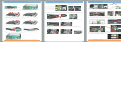
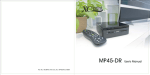
Accessories List
Upgrade / Install CPU
Mainboard Overview
Rear Panel
Riser Card
Connector
DIO Connector x 1
Battery
Easy Installation Guide
EIG
Power DVD
V.7.0
Driver CD
NTI Media
Maker
Option
Riser Card
Option
Socket P Support
Intel Core 2 Duo /
Celeron Processor
CPU’s Power
Consumption ɩ35W
miniCard slot x 1
(for TV Tuner Module)
LPC Connector x 1
Dual Channel Mode,
SODIMM x 2
DDRII 667/800
Max. 4GB
BIOS
90W DC 20V
Power Adapter
S/PDIF
Converter
Power Cord
DVI to DVI+VGA
Y Cable
(MP45-DR only) (MP45-D/MP45-DU)
(by Territory)
DVD Eject Button
DVI to VGA
Converter
Optical Device Drive
DVI to HDMI
Converter
Remote Control
(by Territory)
(MP45-DR only)
Screw of HDD
(4pcs)
Screw of SATA
Card (2pcs)
miniCard slot x 1
(for Wireless Module)
This socket supports FCPGA6 package CPU (Socket P), which is the
latest Core 2 Duo (Penryn) package developed by Intel.
Please don’t put the other CPU.
Rib
CPU Cooler
5
1
3
Front Panel Connector
4
CPUFAN Connector
Screw of
Bluetooth (1pcs)
1. There're tabs which located in the side of SODIMM holder.
Detach the existing memory from the memory slot.
Lock
Fan Duct
USB2.0 Connector x 1
Intel PCIe Gigabit
LAN Chip
2
6
3. Move over the CPU Cooler carefully. Avoid damaging the
component of the mainboard.
Note: When screw the socket. You will hear a slight sound
"Dock". That means you already installed CPU successfully.
7. Fit the CPU Cooler into their respective holes of the mainboard
and use the Phillips(+) screwdriver to tighten screw 1-2-3-4-5-6.
make sure the CPU Cooler is fastened to the mainboard evenly.
Note:
There is one cable connected to
board. Please keep it connected.
If you remove it by accident,
please connect it again.
Intel ICH9M Chipset
IR indicator (MP45-DR only)
HDD indicator
Power indicator
Power Button
Optional Expansion Items
4. Use the Slotted(-) screwdriver to turn CPU socket screw toward
the unlock mark. (Anticlockwise direction)
Disassemble XC mini
Wireless 802.11
Antenna hole
Security Lock
TV Tuner
Antenna hole
Lock
Unlock
3
5
4
2
Top Cover
TV Tuner Kit (ATSC)
TV Tuner Kit (DVB-T)
Top Cover
Key
6
8. Install the Fan Duct Vertically.
Rib
3. Plug in memory module into SODIMM slot with angle 20 ~ 30Ą.
Make sure memory module plug into slot completely.
Fan Duct
CPU Cooler
Unlock
30Ą
1. Disassemble the Top Cover carefully to avoid
scratching the Top Cover.
USB 2.0 Ports
2. Put the memory module with correct direction. Notice there's
one key position to make sure direction is correct.
Realtek HD Audio Codec
1
USB 2.0 Ports
Upgrade / Install Memory Modules
SODIMM slots are designed in high and low positions which are
very easy to recognize. Insert the module straight down to the
SODIMM slot with fingers and press down firmly until the SODIMM
module is securely in place.
1. Take the chassis Module. Use the rib of fan duct to detach the
fan duct.
2. Detach 6 screws of the CPU Cooler by the Phillips(+) screwdriver.
The sequence of operationis 1-2-3-4-5-6.
Intel GM45 Chipset
IR Receiver Connector x 1
3.3V USB 2.0 Connector x 1
(for 3.3V Bluetooth Module)
USB2.0 Port x 2
6. Use the Slotted(-) screwdriver to turn CPU socket screw toward
the Lock mark. (Clockwise direction)
30mm
Rear
Wireless Kit
30mm
Line in
(S/PDIF Out)
Line Out
Front
Microphone
20V DC Jack
DVI-I Port
eSATA Port
Bluetooth Kit
RJ45 LAN Jack
Wireless Antenna
802.11 b/g
AOpen reserves the right to revise all the
specifications and information contained in this
document, which are subject to change without notice.
Wireless 802.11n
Antenna
2. Use the Phillips(+) screwdriver to detach the sheet
metal screws (4pcs).
3. Disassemble the product to two modules (Upper module and
Chassis module).
4
1
DVI to DVI +
D-Sub Cable
Socket Screw
2
Socket Pin1
5. Remove existing CPU, then install new CPU.
Locate Pin 1 in the socket and look for a golden arrow on the
CPU upper interface. Match Pin 1 and golden arrow. Then
insert the CPU into the socket.
3
Processor Number
Architecture
Clock Speed
Front Side Bus
L2 Cache
Support BIOS
Version
Intel Core 2 Duo (Penryn) CPU
Core 2 Duo T9600
45nm
2.80 GHz
1066 MHz
6MB
From R1.00
Core 2 Duo T9400
45nm
2.53 GHz
1066 MHz
6MB
From R1.00
Core 2 Duo P9500
45nm
2.53 GHz
1066 MHz
6MB
From R1.00
Core 2 Duo P8600
45nm
2.4 GHz
1066 MHz
3MB
From R1.00
Core 2 Duo P8400
45nm
2.26 GHz
1066 MHz
3MB
From R1.00
DVI to HDMI Cable
* GM45 support front side BUS 667/800/1066MHz.
Golden Arrow
Part No.: 49.MB401.A110
Doc. No.: MP45DR-EG-E0807B
4. User finger to push memory module vertically until the tabs lock
memory module tightly. Now, the memory modules have been
plugged properly with horizontal flat.
CPU Frequency Table
(Upper module)
(Chassis module)
Socket Pin1
Note: If you do not match the CPU Socket Pin1 and CPU Golden arrow well,
you may damage the CPU.
Note: With CPU speed changing rapidly, there might be faster CPU on the
market by the time you received this installation guide.
This table is kindly for your references only.
Tab
Tab
Upgrade / Installing hard disk drive
1. Take the upper module. Use the Phillips(+) screwdriver to detach
the Riser Card screws and disassemble the Riser Card.
ODD
Connector
XC mini provides two miniCard slots for users to upgrade this PC
functions. Now, the miniCard can have digital TV Tuner and
Wireless LAN miniCard Module …etc. for expansion.
1. Put the upper module on the accessory box or JIG accord the photo.
2. The Bluetooth card.
Antenna Hole (suggest to
assemble the Wireless antenna)
Riser Card
Bluetooth Cable
1. Take the upper module and chassis
module.
2. Fit the golden finger of the upper
module to the Riser Card slot of
the chassis module.
3. The Antenna wire of the Bluetooth card.
4. The Antenna wire was fixed into the wire clip.
5. Take away the Antenna from the wire clip.
2. Use the Phillips(+) screwdriver to detach the HDD screw.
Remove the existing HDD from the upper module.
Antenna Hole (suggest to
assemble the TV Tuner antenna)
1
3
Wire chip
Note: Arrange the wire or fix it by tapes to avoid interfering
with the Riser Card slot from damaging the wire.
3. Use the Phillips(+) screwdriver to fix the sheet metal screws (4pcs).
2
4
1
3
2
4
2
1
4
3
3
6. Take away the protection tube of the Antenna wire.
7. The Bluetooth module and 1pcs BT screw.
Screw size: M2*L4.6 (Torque: 1.0 ² 0.1 Kgf. cm)
8. Fix the Bluetooth module on the holder of the upper module.
9. Tighten the Bluetooth module with screw.
Metal cover
Antenna wire
3. Use the screw driver to detach the miniCard screw of mainboard.
4. Arrange the wireless LAN wire or TV Tuner wire under the
miniCard module.
1
Antenna wire
3.5" FDD
Diskette
LCD Monitor
DVI to HDMI Connector
(by Territory)
Wireless 802.11 Antenna hole
TV Tuner Antenna hole
Line in (S/PDIF out)
4. Press <S> after "S=Specify Additional Device" appears.
5. Use the arrow keys to select "Intel(R) ICH9M-E/M SATA AHCI
Controller".
6. After the SATA driver installation is completed, you can proceed
with the Windows XP installation.
Line out
Security lock
Microphone (MIC)
Internet
Note1:
If installing under Windows
Vista OS, it doesn't have to
do anything for setting.
Protection tube
11. The 3.3V USB connector of the main board.
Concave part
Note:
The Concave part of the Top Cover is toward the front side.
4 pin 5V USB connector
BIOS Setup
5. Insert the miniCard module and fix it with the miniCard screw.
6. Buckle the Antenna wire on the miniCard module and arrange the
wire.
7. Install the antenna.
NoteǺAvoid scratching the golden finger of the Riser Card.
HDMI TV
4. Install the Top Cover carefully to avoid scratching it.
Bluetooth
screw
6. Connect the Riser Card with the connector of the ODD
drive and HDD.
USB FDD
Device
For 3.3V Bluetooth
2
7. Use the Phillips(+) screwdriver to tighten two screws to fix
Riser Card with ODD drive and HDD.
CRT Monitor
Wire chip
1. Remove the metal cover of the antenna hole by the screw driver.
2. Install the antenna wire into the Antenna hole of rear panel.
3. Install the new HDD into the upper module.
4. The hard disk device has to be fixed to the white plastic fixture
with four HDD screws.
5. The operation order is screw 1-2-3-4
DVI to
VGA & DVI
Adapter
(MP45-DR
only)
Bluetooth Module
Antenna wire
4
Projector
Please prepare:
Riser Card Slot
miniCard slot
(suggest to assemble
the Wireless Module)
Golden Finger
Rear Panel Connections
Golden finger
miniCard slot
(suggest to assemble
the TV Tuner Module)
SATA HDD
Connector
Install eSATA when the Windows XP are installed
The following details regarding the eSATA drivers installation with
Windows XP.
1. Prepare USB FDD Device , 3.5" FDD Diskette and Driver CD.
2. Copy eSATA driver into 3.5"FDD Diskette from Driver CD.
3. Boot from the Windows XP setup disk. Press <F6> after the
message "Press F6 if you need to install a third party SCSI of
RAID driver" appears.
Assemble the Top Cover
Bluetooth Assembly
Expansion Slot Installation
4 pin 3.3V USB connector
(to 3.3V Bluetooth)
12. Plug the Bluetooth cable with the connector of the main board.
14. Plug the Bluetooth cable with the connector of the Bluetooth card.
15. Buckle the Bluetooth card with the Antenna wire and arrange
the wire accord the photo.
Note: The 4 pin 5VUSB connector don’t install the 3.3V
Bluetooth module
BIOS Setup when 1st Power On
After finishing the setting of
connect correct cable, power on
and enter the BIOS Setup
screen, then press <DEL>
during POST (Power On Self
Test). Choose "Load Optimized
Defaults" for recommended
optimal performance.
Select ODD name if installing the Windows Vista/XP via ODD
Before the Windows Vista/XP
are installed, please select your
ODD name : Advanced BIOS
Features > First Boot Device to
ODD name. ex. P1MATSHITADVD.
Note2:
If you don't have FDD device, you
must set SATA mode to IDE mode,
but the external HDD can not
support HOT PLUG.
1. Turn on your computer. Press
<Del> to enter BIOS setup.
2. Set OnChip IDE mode >
SATA mode to IDE.
3. Save and exit BIOS Setup.
eSATA Port
DSL (Cable) Modem
USB 2.0 Port
Expander (USB HUB)
Wall Outlet
FAX/Scanner/Printer
Bluetooth Dongo
Wireless Lan Card
USB TV Tuner BOX
USB HDD
Dual Display Arrangement
Install Driver
You can use the autorun menu of Bonus CD disc. Choose the utility
and driver from the icons at left side, and then click on the "GO"
button to complete installation automatically.
Install
Driver
DVI to DVI +
VGA Cable
(MP45-DR only)
Install
Utility
Browse CD
Contents
LCD Monitor
Support DVI
Readme
Exit CD
CRT Monitor
Support VGA
PDA
Card reader/Flash memory
Web camera
Joystick
Mouse/Keyboard