1
4.8. COUPLING ALGORITHMS - SEQ AND LAG CONCEPTS
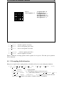
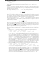
Model B timestep = 6
12
6
0
F1
F2
F1 F3
F1
F2 F3
F3
F2 F1 F3
18
17
24
F2
F1 F3
F1
F2 F3
F2 F1 F3
30
F2
120
F1 F3
F2
F2
F3
0
F1 F2 F3
6
12
Model A timestep = 6
Cpl_period(F1) = 12
Cpl_period(F2) = 12
Cpl_period(F3) = 12
LAG(F1) = 6
LAG(F2) = 6
LAG(F3) = 0
18
F1 F2 F3
24
F2 F3
F1
120
prism_put_proto/prism_get_proto leading to
writing/reading to/from coupling restart file
prism_put_proto/prism_get_proto leading to
sending/receiving actions
prism_put_proto/prism_get_proto NOT leading to
sending/receiving actions
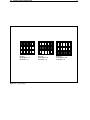
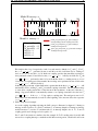
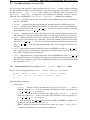
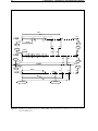
Figure 4.5: LAG concept second example
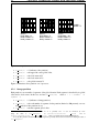
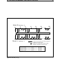
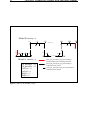
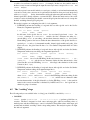
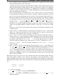
This implies that a lag of respectively 4 and 6 seconds must be defined for F 1 and F2 . For F1 ,
the prism put proto performed at time 8 and 20 by model A will then lead to sending actions (as 8 + 4 = 12 and 20 + 4 = 24 which are coupling periods) that match the receiving actions performed at times 12 and 24 below the prism get proto called by model B. For F 2 , the
prism put proto performed at time 18 by model B then leads to a sending action (as 18 + 6
= 24 which is a coupling period) that matches the receiving action performed at time 24 below the
prism get proto called by model A.
At the beginning of the run, as their LAG index is greater than 0, the first prism get proto will
automatically lead to reading F1 and F2 from their coupling restart files. The user therefore have
to create those coupling restart files for the first run in the experiment. At the end of the run, F 1
having a lag greater than 0, is automatically written to its coupling restart file below the last F 1
prism put proto if the date + F1 lag equals a coupling time. The analogue is true for F 2 .
These values will automatically be read in at the beginning of the next run below the respective
prism get proto .
2. LAG concept second example
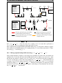
A second coupling algorithm exploiting the LAG concept is illustrated on figure 4.5. During its
timestep, model A receives F2 , sends F3 and then F1 ; its timestep length is 6. During its timestep,
model B receives F1 , receives F3 and then sends F2 ; its timestep length is also 6. F1 , F2 and F3
coupling periods are both supposed to be equal to 12.
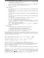
For F1 and F2 the situation is similar to the first example. If F 1 /F2 sending action by model A/B
was used at a coupling timestep to match the model B/A receiving action, a deadlock would occur