1
RT-MaG ToolBox
User’s guide
Augustin Manecy
March 21, 2014
Contents
1 Description
1.1 Application structure . . . . . . . . . . . . . . . . . . . . . . . . . . . . . . . . . . . . . . . . . . .
1.2 Toolbox’s workflow . . . . . . . . . . . . . . . . . . . . . . . . . . . . . . . . . . . . . . . . . . . .
2 Starter guide
2.1 Requirements . . . . . . . . . . . . . . . .
2.2 RT-MaG tools for your COM . . . . . . .
2.2.1 Development computer tools . . .
2.2.2 COM tools . . . . . . . . . . . . .
2.2.3 Other tools . . . . . . . . . . . . .
2.3 Create a model . . . . . . . . . . . . . . .
2.3.1 Simulink configuration parameters
2.3.2 The I/Os blocks . . . . . . . . . .
2.3.3 COM configuration block . . . . .
2.4 Generate the Standalone application . . .
2.4.1 GenereCOM . . . . . . . . . . . .
2.4.2 GenereHost . . . . . . . . . . . . .
2.5 Run your application . . . . . . . . . . . .
2.5.1 COM part . . . . . . . . . . . . . .
2.5.2 Host part . . . . . . . . . . . . . .
.
.
.
.
.
.
.
.
.
.
.
.
.
.
.
.
.
.
.
.
.
.
.
.
.
.
.
.
.
.
.
.
.
.
.
.
.
.
.
.
.
.
.
.
.
.
.
.
.
.
.
.
.
.
.
.
.
.
.
.
.
.
.
.
.
.
.
.
.
.
.
.
.
.
.
.
.
.
.
.
.
.
.
.
.
.
.
.
.
.
.
.
.
.
.
.
.
.
.
.
.
.
.
.
.
.
.
.
.
.
.
.
.
.
.
.
.
.
.
.
.
.
.
.
.
.
.
.
.
.
.
.
.
.
.
.
.
.
.
.
.
.
.
.
.
.
.
.
.
.
.
.
.
.
.
.
.
.
.
.
.
.
.
.
.
.
.
.
.
.
.
.
.
.
.
.
.
.
.
.
.
.
.
.
.
.
.
.
.
.
.
.
.
.
.
.
.
.
.
.
.
.
.
.
.
.
.
.
.
.
.
.
.
.
.
.
.
.
.
.
.
.
.
.
.
.
.
.
.
.
.
.
.
.
.
.
.
.
.
.
.
.
.
.
.
.
.
.
.
.
.
.
.
.
.
.
.
.
.
.
.
.
.
.
.
.
.
.
.
.
.
.
.
.
.
.
.
.
.
.
.
.
.
.
.
.
.
.
.
.
.
.
.
.
.
.
.
.
.
.
.
.
.
.
.
.
.
.
.
.
.
.
.
.
.
.
.
.
.
.
.
.
.
.
.
.
.
.
.
.
.
.
.
.
.
.
.
.
.
.
.
.
.
.
.
.
.
.
.
.
.
.
.
.
.
.
.
.
.
.
.
.
.
.
.
.
.
.
.
.
.
.
.
.
.
.
.
.
.
.
.
.
.
.
.
.
.
.
.
.
.
.
.
.
.
.
.
.
.
.
.
.
.
.
.
.
.
.
.
.
.
.
.
.
.
.
.
.
.
.
.
.
.
.
.
.
.
.
.
.
.
.
.
.
.
.
.
.
.
.
.
.
.
.
.
.
.
.
.
.
.
.
.
.
.
.
.
.
.
.
.
.
.
.
.
2
2
3
4
4
4
4
4
4
4
5
5
6
6
7
10
10
10
11
3 Advanced functionalities
12
3.1 The debug modes . . . . . . . . . . . . . . . . . . . . . . . . . . . . . . . . . . . . . . . . . . . . . 12
3.2 The synchronization protocols . . . . . . . . . . . . . . . . . . . . . . . . . . . . . . . . . . . . . . 12
1
1
Description
This toolbox consists of a rapid prototyping tool chain for autonomous robotic applications using Matlab
Simulink. This toolbox allows to program and monitor directly a Computer On Module (COM) through
Matlab Simulink. RT-MaG toolbox frees the users from writing low level language code. RT-MaG toolbox
gives direct access to the I/Os through intuitive masked Simulink blocks. Finally, the user just needs to design
its Simulink model with the wished I/Os, as done for example with dSPACE, or MPLAB 16-Bit Device Blocks
for Simulink. Then a simple call to a function allows to generate the complete standalone real-time application
of this Simulink model. To summarize the RTMAG toolbox allows to:
• automatically generate a multi-rate real-time application from a Simulink model for a real-time embedded
Linux environment,
• make the developments really easy, fast and bug free,
• develop the Gumstix Simulink model directly in 32-bits floating point,
• monitor, log and plot data sent by the COM in real-time via a Serial or a Wifi connection,
• design applications fully compatible with all Simulink blocks (embedded matlab function, s-function,
matlab data-structure...),
• send in real time high level set-points for the controllers embedded on the COM,
• tune in real time controller’s gains and parameters thanks to a Simulink host computer’s application,
• have the possibility to start and stop the application at any time (thanks to the wireless connection),
• monitor continuously the CPU load, overruns and the execution time of each task,
• have an access to a ”debug mode”: detailed execution time of each task, time of I/Os access, and a clear
message for I/Os errors,
• test programs both in Processor-In-the-Loop (PIL) and RunTime mode
The toolbox will configure automatically the COM and you can be concentrated only on the control of your
robot.
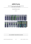
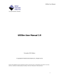
1.1
Application structure
a)
b)
PIL mode
Host Computer
Quarc Real-Time
Windows Target
Robot Model
Sensors
Actuators
Embedded Linux 3.5.0
WIFI
High level
SetPoints,
parameters
WIFI
Embedded Simulink
Model:
Sensors values
High level
SetPoints,
parameters
Quarc Real-Time
Windows Target
WIFI
Set Points
High level SetPoints
Parameters
Monitoring
Estimates,
control inputs...
Estimates,
control inputs...
Serial
root@gumstix:~$
Task
monitoring
WIFI
Host Computer
Consol Application
Linux
Commands
Task
monitoring
root@gumstix:~$
Set Points
High level SetPoints
Parameters
Monitoring
Gumstix
Linux
Commands
Consol Application
RunTime mode
Serial
Serial
Control inputs
Sensors values
Serial
Control inputs
Figure 1: a) The Processor-In-the-Loop mode allows to validate and test the robotic application in real-time
on the COM, without damaging the robot. Here the PIL was used to validate the controllers of the X4-MaG
Quadrotor. The host computer could be used to emulate the RS232 connection of a low level controller and to
simulate the robot behaviour. b) The RunTime mode, i.e. when the robot is running. This application has
the same interfaces than in the PIL mode. As it could be seen, the application of the COM remains the same
which avoid new bug to appear.
The RT-MaG applications are composed of two parts:
2
• a real-time embedded application which executes in real-time a Simulink model on a Computer-On-Module
(COM) to control a robot,
• a real-time host application which executes in real-time a Simulink model on a host computer. The host
computer is used not only to send high level setpoints and parameters to the embedded application but
also to monitor all the signals the users want to check.
The COM application could be monitored by two ways:
• a ssh connection via a console application (e.g., PUTTY) to monitor the CPU load, the eventual overruns,
I/Os error, etc.
• the host Simulink application to monitor the computations.
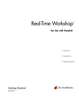
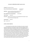
1.2
Toolbox’s workflow
RT-MaG generates then the two real-time applications, the steps are described by the figure 2:
HOST COMPUTER
Real-Time
Parameters Tuning & Monitoring
HOST
Simulink Model
C-Code
Generation
MATLAB ®
Embedded
Coder
COM
Simulink Model
C-Code
Generation
Encapsulation
for Real-Time Execution
Compilation
for Real-Time Win64
Archive
Generation
Real-Time Windows Target
FTP Server
Wifi
COM
Linux
C-Code
compilation
gcc
Real-Time
Execution
Linux Kernel
PREEMPT-RT Patch
I/Os DRIVERs
Figure 2: WorkFlow to generate the real-time application, all these steps are done almost automatically.
Figure 2 describes the different steps performed by the toolbox to obtain a real-time application. When the
Simulink model of the COM is completed, the toolbox generates automatically an archive containing all the files
which are required to be compiled. The host real-time application is also generated as an external application
which could be tuned and monitor in real-time thanks to QUARC. Once the application have been generated
their is two different part:
• An archive (.zip) containing all the files needed to build the standalone application on the COM. This
archive was automatically copied to the FTP server before to be downloaded by the COM to be build,
• A windows real-time Simulink application (.rt-win64) which will be executed by an external real-time
target (QUARC) connected to the Simulink model. In this Simulink model it is possible to visualize in
real-time the signals received from the COM by an UDP connection and to send parameters to the COM.
This model could be used to simulate a robot behaviour in a PIL context.
3
2
Starter guide
2.1
Requirements
To follow this tutorial, you have to prepare your COM to run RT-MaG programs. Please refer to the download
page of our website to flash your COM with one of Linux images if your COM is supported. Or refer to RTMaG ToolBox Prepare your COM.pdf guide to make your COM ready to run RT-MaG programs if their is no
images available for your COM.
2.2
RT-MaG tools for your COM
2.2.1
Development computer tools
Here you can find a description of what is present in the toolbox archive. Once the archive of the toolbox was
inflated and installed, you can explorer the different directories:
• README.txt: a file with some basic instructions to install RT-MaG and a description of the current
version.
• Install RT MaG ToolBox*.*: the installation files of the toolbox. To install the toolbox, run Matlab
with administrator privileges and execute Install RT MaG ToolBox.m.
• RT MaG ToolBox : all the files of the toolbox containing all the functions, library blocks, etc.
• Projects COM : A directory containing all the demonstration models. You can find here:
– Test Gumstix : A directory containing al lot of different models to validate that the toolbox is correctly
installed.
You can generate all these model for your COM by running the TEST COM IO BLOCKs.m
– Test HIL: An example of an PIL project containing the host and the COM model.
You can generate these two model for execution by running init COM Test HIL.m and
init QUARC Test HIL.m
– Test RunTime: Test HIL: An example of RunTime project containing the host and the COM model.
You can generate these two model for execution by running init COM Test RunTime.m and
init QUARC Test RunTime.m
Remark 1: Note that all the Matlab functions and scripts of the toolbox provide an help menu. To access
to the help, you can just type >> help FunctionName in your Matlab command window.
2.2.2
COM tools
The RT-MaG toolbox offers to you some shell scripts allowing to automatize different step of the application
generation. You can find here a small description of each script:
• UpToDateModel <ModelName>: This script downloads the model called <ModelName> and build it automatically in your COM.
• RunModel <ModelName> -d <Duration>: This script executes the model <ModelName> on your COM for
a duration of <Duration>.
• CompileTestModel: This script downloads automatically and compile all the test models available in
the folder your RT-MaG Folder/Projects COM/Test Gumstix. You just have to generate the archives
before in your development computer.
• PutFTP: A simple script to put a file from your COM to the FTP server available on your development
computer.
2.2.3
Other tools
The RT-MaG toolbox provides also set of functions to compute different representation of rotations (Euler
angles, rotation matrix, quaternion). You can obtain a list of the available functions as their description (help
menu) like this:
2.3
Create a model
In this part you can find how to build rapidly a model step by step with a lot of customization.
First you have to create a new blank Simulink model.
4
Figure 3: The list of the functions of the rotation tools provided by the RT-MaG toolbox.
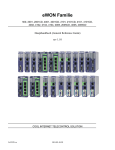
2.3.1
Simulink configuration parameters
As the c-code of the Simulink model will be generated by Embedded coder, you need first configure the code
generator:
4) Choose here the
compiler optimization level
3) Choose the
1) Choose a fixed step
System target
solver (discrete or ode1)
file:
Embedded Code (ert.tlc)
2) Use "ComMinSampleTime" as
fundamental sample time.
Figure 4: How to configure your Simulink model in the Configuration Parameters
2.3.2
The I/Os blocks
If the RT-MaG tooblox has been correctly installed the RT-MaG toolbox, you can find all the I/Os block
available in your Simulink browser: You just have to add the I/Os blocks you need for your application as
Inputs Blocks
Outputs Blocks
The COM library
blocks
The HOST
library blocks
Figure 5: How to configure your Simulink Figure 6: The inputs and Outputs block of the RT-MaG toolbox:
model in the Configuration Parameters
SPI, I2C, File logging, PWM, RS232, UDP.
5
classic Simulink I/O blocks. You just have to respect the limitation of each I/Os, e.g., a emission and reception
RS232 block need to use the same baudrate if they use the same device. The limitations of each blocks are
described on the RT-MaG website in the Tutorials&Documentations section.
2.3.3
COM configuration block
To configure properly your real-time application, the RT-MaG
toolbox provides a configuration block allowing to choose in a
large-wide of options:
• Time scheduler choice (timer, or I/O interrupt),
• tasking mode (multi task or single task application),
• I/O debug modes (via the console or via a file),
• Timing debug modes (via the console or via a file),
• Synchronization protocol
A detailed description of this block is given here on our website.
Figure 7: The COM configuration block of
RT-MaG.
Each Simulink model destined to be run on a COM needs this block. There can have only one configuration
block per model. You have to choose carefully all the options of this block because it manage how the application
will be executed. The I/Os and timing debug modes are really useful to detect a misconfiguration but keep in
mind they can slow down your application.
2.4
Generate the Standalone application
To generate the two models (Embedded and Host) you just built, you just have to run the following Matlab
commands:
>> GenereHost ( ModelName , HostSampleTime )
>> GenereCOM( ModelName , ComSampleTime )
As you can see, these two functions need you to specify a sample time, which corresponds to the minimum
sample time of your model. The sample time you will pass as argument will be then assigned in your Matlab
6
workspace as HostMinSampleTime and ComMinSampleTime for the host and the COM respectively. This is the
variable given to the Simulink Configuration Parameters as the solver fixed-step sample time (fundamental
sample time).
As a consequence if you use these two variables (HostMinSampleTime and ComMinSampleTime) in your model,
you can easily generate the application for different sample time.
2.4.1
GenereCOM
As said previously, the generation of the sources needed to build the COM application is done by the command:
>> GenereCOM( ModelName , ComSampleTime )
The GenereCOM function evaluates all the mask of the different I/Os blocks present in your Simlink model and
generates two structures in the workspace. These structures allow to check automatically that each I/O block
are correctly used and they can work with the other I/O blocks. If their exist incompatibilities between different
blocks, error messages will appear in the Matlab command window. You can display these two structure in the
Matlab command window like this:
>>D i s p S t r u c t ( Gumstix )
UDP( 1 ) :
Emission ( 1 ) :
Name : Out to UDP
NbData : 69
DataType : f l o a t 3 2
IPaddress : 192.168.137.2
Port : 2012
I n t e r f a c e : wlan0
SampleTime : 0 . 0 0 5
RS232 ( 1 ) :
Reception (1) :
Name : I n f r o m S e r i a l
NbData : 11
DataType : i n t 1 6
PortIndex : 2
Port : / dev / ttyO2
BaudRate : 115200
SampleTime : 0 . 0 0 5
BlockingReception : 1
Configuration (1) :
TimeScheduler : RS232 R e c e p t i o n
ConsoleVerbose : o f f
FileVerbose : o f f
TimeLogger : on
TimingDebug : o f f
FileTimingDebug : o f f
SynchroRS232 ( 1 ) :
Type : Send−Wait
TimeOut : 100
Message : START
TaskingMode : Multi−Tasking
>>D i s p S t r u c t ( I O 2 P r o c e s s )
UDP:
Reception : 0
Emission : 1
RS232 :
Reception : 1
Emission : 0
PortData : { ’ / dev / ttyO2 ’
[2]
[115200]}
As you can see, these structures summarize all the I/O informations useful to generate the archive.
The GenereCOM function will also generate a lot of different files an directories. Some files and directories
are generated by Embedded Coder itself and the other are generated by RT-MaG toolbox. Here you can find a
rapid description of the main generated files and directories and their signification:
• directories:
7
– slprj is a directory generated by Simulink which contains some files used during the code generation.
This folder is not useful after and can be deleted.
– COM ModelName ert rtw is a directory generated by Embedded Coder, it contains all the c-files
needed to declare the Simulink variables an realizes the model functions. Some of theses files were
used by RT-MaG toolbox during the generation, but you can delete this folder if you want.
– To Build COM ModelName is the directory generated by RT-MaG toolbox. It contains all the files
needed to generate the standalone application on your COM (included the main part of the Embedded
Coder files contained in the folder COM ModelName ert rtw). For a sake of simplicity an archive of
this folder is available into it, and was also copied on your FTP server (COM ModelName sources.zip).
• files:
– In the folder COM ModelName ert rtw their is ert main.c which is a simple example (provided
by Embedded Coder) of how to use and call the generated function in a standalone application. As
you can see, the I/Os attribution, the interrupts, etc. are not done in this file, and that why the
RT-MaG toolbox exists.
– COM ModelName.zip is an archive generated by Embedded Coder containing a lot of file but you
does not need this. This file can be deleted.
– In the folder To Build COM ModelName their is a file main COM ModelName.c. This file is the
main file of the RT-MaG application.
– In the folder To Build COM ModelName their is a file genere RT COM ModelName. This shell
script allows to build the model on the COM and will be used by the shell script UpToDate (see
section 2.5).
The minimum sample time
ComMinSampleTime
The minimum sample time
ComMinSampleTime
The structures Gumstix
and IO_2_Process
The structures Gumstix
and IO_2_Process
The minimum sample time
ComMinSampleTime
Figure 8: The folders and the workspace variables obtain after a COM generation
Here is an example of the COM’s model generation for the test model InOut Full MultiTask Clock:
RT−MaG#
RT−MaG#
RT−MaG#
RT−MaG#
RT−MaG#
Remove p r e v i o u s b u i l d d i r e c t o r i e s . . .
Try t o remove : C O M I n O u t F u l l M u l t i T a s k C l o c k e r t r t w . . .
Done !
Try t o remove : ToBuild COM InOut Full MultiTask Clock . . .
Done !
RT−MaG# G e n e r a t i o n o f code f o r COM u s i n g Embedded Coder
COM InOut Full MultiTask Clock . . .
### S t a r t i n g b u i l d p r o c e d u r e f o r model : COM InOut Full MultiTask Clock
8
### G e n e r a t i n g code i n t o b u i l d f o l d e r :
D: \TOOLBOX\RT MaG\ Projects COM \ Test Gumstix \ C O M I n O u t F u l l M u l t i T a s k C l o c k e r t r t w
### I n v o k i n g Target Language Compiler on COM InOut Full MultiTask Clock . rtw
### Using System Target F i l e : C: \ Program F i l e s \MATLAB\R2011b\ rtw \ c \ e r t \ e r t . t l c
### Loading TLC f u n c t i o n l i b r a r i e s
......
### I n i t i a l p a s s through model t o c a c h e u s e r d e f i n e d code
...
### Caching model s o u r c e code
........................................................................
### W r i t i n g h e a d e r f i l e COM InOut Full MultiTask Clock . h
.
### W r i t i n g h e a d e r f i l e C O M I n O u t F u l l M u l t i T a s k C l o c k t y p e s . h
### W r i t i n g h e a d e r f i l e r t w t y p e s . h
.
### W r i t i n g h e a d e r f i l e r t G e t I n f . h
### W r i t i n g s o u r c e f i l e r t G e t I n f . c
.
### W r i t i n g h e a d e r f i l e rtGetNaN . h
### W r i t i n g s o u r c e f i l e rtGetNaN . c
.
### W r i t i n g h e a d e r f i l e r t n o n f i n i t e . h
### W r i t i n g s o u r c e f i l e r t n o n f i n i t e . c
.
### W r i t i n g s o u r c e f i l e COM InOut Full MultiTask Clock . c
### W r i t i n g h e a d e r f i l e C O M I n O u t F u l l M u l t i T a s k C l o c k p r i v a t e . h
.
### W r i t i n g s o u r c e f i l e COM InOut Full MultiTask Clock data . c
### W r i t i n g s o u r c e f i l e e r t m a i n . c
.
### TLC code g e n e r a t i o n c o m p l e t e .
### C r e a t i n g p r o j e c t marker f i l e : r t w p r o j . tmw
### E v a l u a t i n g PostCodeGenCommand s p e c i f i e d i n t h e model
### S u c c e s s f u l c o m p l e t i o n o f code g e n e r a t i o n f o r model : COM InOut Full MultiTask Clock
RT−MaG# Begin t o g e n e r e code f o r t h e StandAlone a p p l i c a t i o n u s i n g
. \ COM InOut Full MultiTask Clock ert rtw :
RT−MaG# G e n e r a t i n g main f i l e : main COM InOut Full MultiTask Clock . c . . .
RT−MaG#
Generating headers i n c l u d e s . . .
RT−MaG#
Generating g l o b a l v a r i a b l e s . . .
RT−MaG#
G e n e r a t i n g I /O p r o p e r t e r m i n a t i o n . . .
RT−MaG#
G e n e r a t i n g I n p u t s a t t r i b u t i o n f o r Sample Time : 0 . 1 [ s ] . . .
RT−MaG#
G e n e r a t i n g Outputs a t t r i b u t i o n f o r Sample Time : 0 . 1 [ s ] . . .
RT−MaG#
G e n e r a t i n g I n p u t s a t t r i b u t i o n f o r Sample Time : 0 . 0 1 [ s ] . . .
RT−MaG#
G e n e r a t i n g Outputs a t t r i b u t i o n f o r Sample Time : 0 . 0 1 [ s ] . . .
RT−MaG#
G e n e r a t i n g I n p u t s a t t r i b u t i o n f o r Sample Time : 0 . 0 0 5 [ s ] . . .
RT−MaG#
G e n e r a t i n g Outputs a t t r i b u t i o n f o r Sample Time : 0 . 0 0 5 [ s ] . . .
RT−MaG#
G e n e r a t i n g I n p u t s a t t r i b u t i o n f o r Sample Time : 0 . 0 0 3 [ s ] . . .
RT−MaG#
G e n e r a t i n g Outputs a t t r i b u t i o n f o r Sample Time : 0 . 0 0 3 [ s ] . . .
RT−MaG#
G e n e r a t i n g I n p u t s a t t r i b u t i o n f o r Sample Time : 0 . 0 0 2 [ s ] . . .
RT−MaG#
G e n e r a t i n g Outputs a t t r i b u t i o n f o r Sample Time : 0 . 0 0 2 [ s ] . . .
RT−MaG#
G e n e r a t i n g I n p u t s a t t r i b u t i o n f o r Sample Time : 0 . 0 0 1 [ s ] . . .
RT−MaG#
G e n e r a t i n g Outputs a t t r i b u t i o n f o r Sample Time : 0 . 0 0 1 [ s ] . . .
RT−MaG#
G e n e r a t i n g I /O i n i t i a l i z a t i o n . . .
RT−MaG#
G e n e r a t i n g s p e c i f i c main ’ s argument p r o c e s s i n g . . .
RT−MaG# G e n e r a t i n g d e f i n e s f i l e : d e f i n e s v e r d e x . h . . .
RT−MaG# G e n e r a t i n g s h e l l s c r i p t f i l e : genere RT COM InOut Full MultiTask Clock . . .
RT−MaG# G e n e r a t i n g c o m p l e t e b u i l d d i r e c t o r y :
. \ ToBuild COM InOut Full MultiTask Clock
Copying l i b r a r y I 2 C . c . . .
Copying library LOG . c . . .
Copying library PWM . c . . .
Copying l i b r a r y S P I . c . . .
Copying l i b r a r y r s 2 3 2 . c . . .
Copying l i b r a r y u d p . c . . .
Copying t i m e t o o l s . c . . .
9
Copying l i b r a r y I 2 C . h . . .
Copying library LOG . h . . .
Copying library PWM . h . . .
Copying l i b r a r y S P I . h . . .
Copying l i b r a r y r s 2 3 2 . h . . .
Copying l i b r a r y u d p . h . . .
Copying t i m e t o o l s . h . . .
Copying COM InOut Full MultiTask Clock . c . . .
Copying COM InOut Full MultiTask Clock data . c . . .
Copying main COM InOut Full MultiTask Clock . c . . .
Copying r t G e t I n f . c . . .
Copying rtGetNaN . c . . .
Copying r t n o n f i n i t e . c . . .
Copying COM InOut Full MultiTask Clock . h . . .
Copying C O M I n O u t F u l l M u l t i T a s k C l o c k p r i v a t e . h . . .
Copying C O M I n O u t F u l l M u l t i T a s k C l o c k t y p e s . h . . .
Copying d e f i n e s v e r d e x . h . . .
Copying r t G e t I n f . h . . .
Copying rtGetNaN . h . . .
Copying r t n o n f i n i t e . h . . .
Copying r t w t y p e s . h . . .
RT−MaG# Echo−P r o c e s s i n g f o r VERDEX sources . . .
p r i n t f : OFF
f p r i n t f : OFF
e x e c u t i o n time p r i n t f : OFF
e x e c u t i o n time f p r i n t f : OFF
RT−MaG# G e n e r a t i n g c o m p l e t e a r c h i v e : C O M I n O u t F u l l M u l t i T a s k C l o c k s o u r c e s . z i p . . .
RT−MaG# Copying s h e l l s c r i p t i n : . \ ToBuild COM InOut Full MultiTask Clock . . .
RT−MaG# Copying A r c h i v e and s h e l l s c r i p t on FTP d i r e c t o r y . . .
.
RT−MaG# GENERATION OF CODES COMPLETED SUCCESSFULLY !
RT−MaG# You can b u i l d t h i s model u s i n g . / UpToDateCOM InOut Full MultiTask Clock on
your COM
RT−MaG# Then you can run t h i s model u s i n g . / RunModelCOM InOut Full MultiTask Clock −d
<d u r a t i o n > on your COM
2.4.2
GenereHost
As said previously, the generation of the real-time Simulink model for the host application is done by the
command:
>> GenereHost ( ModelName , HostSampleTime )
This command creates a ModelName.rt-win64 application which will be used by the Quarc real-time target.
Take a look to the section 2.5.2 to know how to use and run this model in real time.
2.5
Run your application
2.5.1
COM part
Now, you just need to download and compile the archive generated in the subsection 2.4.1. So, turn on your
COM, log on, and go to the RT-MaG directory to build your application. If you use one of our RT-MaG Linux
image, you can proceed as follow:
login : root
root@overo ˜ : cd RT MaG Toolbox/RT MaG Program
Then, the archive can be automatically downloaded and compiled on the COM using the Linux command:
root@overo ˜ : . / UpToDateModel ModelName
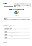
You will obtain something like the figure 9 for the compilation. The archive is downloaded, then you can choose
to define some macros (to activate some debug mode even if their are not activated on the Simulink model).
Finally, the archive is inflated and the program is compiled.
Then the real-time application could be executed with the command:
10
Recover the archive
from FTP server
Initialization of
the different I/Os
Choose if you want to define macros
Inflate the archive
Synchronization protocols
CPU load
Monitoring
at 1Hz
Termination and
t
statistics about
execution time
Compile the model
Figure 10: Results of the RunModel command for a
duration of 5 seconds.
Figure 9: Results of the UpToDateModel command.
root@overo ˜ : . / RunModel ModelName −d MyDuration
where MyDuration is the time during which the application has to be executed. You can find an example of
a program execution in figure 10.
After the inputs and outputs initialization, the synchronization protocols are executed on the RS232 device
to check that the remote device is ready (optional). Then the program begins and the CPU load is plotted
each second. In addition, if overruns occur for some task their are plotted immediately. When the program
finishes, it displays some statistics about execution times and eventual overruns and it frees the devices used
by the program.
Remark 2: During an execution, you can type CTRL+C to quit immediately and properly the program,
i.e., the program will free all the resources and quit.
2.5.2
Host part
Once the ModelName.rt-win64 was generated for your host model, you just have to load it on the real-time
Quarc target and then to play it. During the execution of the model, you will be able to modify all the parameter
you want in the host model. If you send this parameter to your COM model via UDP, you will be able to tune
your controller parameters running on the COM model. This is the ideal way to achieve rapid prototyping of
controllers in real-time.
11
To run this model, you need first to load it on the real-time target which will execute this model in real-time.
To do this just click on ”Connect-to-target” as described by the figure 11. Once the target is connected, you can
Figure 11: The connect to target step for loading the model on the real-time target before running it.
run the model by simply click on ”Start real-time code” as described by figure 12. Then during the simulation
Figure 12: The start real-time code step for running a real-time Simulink model on the host computer.
you can change every parameters you want and it will take effect immediately.
3
Advanced functionalities
3.1
The debug modes
You can activate in the configuration block described in section 2.3.3 different debug modes. These different
mode allow to detect eventual I/O failure due to misconfiguration, hardware failure or missing remote device.
You have three kind of debug modes:
• Input-Output Verbose: When activated this mode reports all the Inputs and Outputs results, i.e., the
number of received data, their values, and the eventual failure (unavailable resource, etc.). The results
can be plotted in real-time in the console or just written in a .debug file.
• Timing Debug: When activated this mode reports the execution time of each task, i.e., the duration of
each I/O access, the duration of each task. The results can be plotted in real-time in the console or just
written in a .debug file.
• Time Logger: When activated this mode reports the execution time of each task in a file. The only
difference between the previous debug mode is it reports the time of a complete task (Inputs of the task
+ the task + Outputs of the task).
Remark 3: You can also activate these debug mode by defining macros during the compilation of the application
on your COM. This is an interesting thing because you are not obliged to generate the archive again. At the
question ”Do you want define macro for the compilation?”, respond ”y” and the define one or several of this
macro, separated buy a space:
• ECHO PRINTF: to activate the inputs-outputs verbose mode in a console,
• ECHO FPRINTF: to activate the verbose mode in a file,
• ECHO PRINTF TIME: to activate the timing debug mode in a console,
• ECHO FPRINTF TIME: to activate the timing debug mode in a file,
3.2
The synchronization protocols
For the RS232 connection, you can choose to activate or not a synchronization protocol. As it is not possible in
a RS232 bus to separate frame, you can choose to activate a synchronization protocol. This protocol consists
in a simple stream, send at the beginning of the program allowing to say to the remote device that the program
begins. This synchronization protocol consists in a Start stream which is send to the remote device, and the
program starts when the remote device sends the same start stream in response.
Remark 4: If a synchronization protocol fails, the program will not begin and you can see what fail. For
example, which start stream was received back. A synchronization protocol fail often occur if the baudrate of
your RS232 device and the remote device are not the same.
12
13