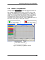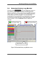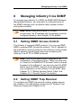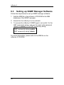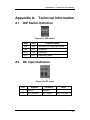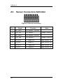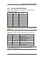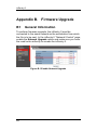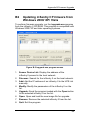
1
inSentry II
User’s Guide
Version 1.0
© Copyright 2007. Ingrasys Technology Inc. All rights reserved.
inSentry II
Copyright
© Copyright 2007. Ingrasys Technology Inc. All rights
reserved.
Trademarks
AT and IBM are registered trademarks of International
Business Machines Corporation.
NetWare is a registered trademark of Novell, Inc.
Windows 2000, XP, Vista are registered trademarks of
Microsoft Corporation.
All other trademarks belong to their respective proprietors.
Electronic Emission Notice
Federal Communications Commission
This equipment has been tested and found to comply with the
limits for a Class B digital device, pursuant to Part 15 of the
FCC Rules. These limits are designed to provide reasonable
protection against harmful interference when the equipment is
operated in a commercial environment.
CE Notice
This device complies with the EMC directive of the European
Community and meets or exceeds the following technical
standard:
• EN 55022:1998 – “Limits and Methods of Measurement of
Radio interference Characteristics of information
Technology Equipment.” This device complies with the
CISPR Class B standard.
• EN 55024:1998 – ”Electromagnetic compatibility –
Generic immunity standard Part1: Residential, and light
industry.”
RoHS
This device is RoHS compliant.
2
Safety Information
Safety Information
•
•
•
•
•
•
•
To reduce the risk of fire or electric shock, install the unit
in a temperature-controlled indoor area free of conductive
contaminants. Do not place the unit near liquids or in an
excessively humid environment.
Do not allow liquids or foreign objects to enter the unit.
The unit does not contain any user-serviceable parts. Do
NOT open the unit.
All the services of this equipment must be performed by
qualified service personnel.
Remove all metallic jewelry or other accessories before
servicing the unit.
Before maintenance, repair or shipment, the unit must be
completely switched off and unplugged and all
connections must be removed.
Before connecting the inSentry II to the power supply,
make sure the rating of power source is consistent with
the rating of power adapter of the inSentry II.
3
inSentry II
Table of Contents
Electronic Emission Notice.................................................. 2
Safety Information................................................................. 3
1 Introduction..................................................................... 7
1.1 Features ..................................................................... 7
1.2 Package Contents...................................................... 8
1.3 Front View .................................................................. 9
1.4 Rear View................................................................... 9
2 Installation..................................................................... 10
2.1 Installing inSentry II via Serial Port .......................... 10
2.2 Installing inSentry II via LAN .................................... 13
2.3 LED Definitions ........................................................ 15
3 Configuration ................................................................ 17
3.1 Configuring inSentry II via Serial Port ...................... 17
3.1.1
inSentry II Configuration.................................. 20
3.1.1.1
3.1.1.2
3.1.1.3
Setting System Group ......................................... 21
Setting Control Group.......................................... 21
Setting Parameter Group .................................... 22
3.1.2
EMD Configuration .......................................... 23
3.1.3
Setting Access Control Table .......................... 25
3.1.4
Setting Trap Receivers.................................... 27
3.1.5
Resetting Configuration to Default .................. 27
3.1.6
Restarting inSentry II....................................... 28
3.1.7
Exiting inSentry II Console Configuration........ 28
3.2 Configuring inSentry II via Telnet............................. 29
4 Managing inSentry II via Web Browser ...................... 30
4.1 Manipulating Network Routing Table in Windows ... 30
4.2 Initial Configuration .................................................. 31
4.3 Monitoring ................................................................ 32
4.3.1
Summary ......................................................... 33
4
Table of Contents
Detail View....................................................... 34
4.3.2
4.3.3
Identification .................................................... 35
4.3.4
Alarms ............................................................. 35
4.4 Configuration............................................................ 36
4.4.1
Sensor ............................................................. 36
4.4.1.1
4.4.1.2
4.4.1.3
4.4.2
4.4.2.1
4.4.2.2
4.4.2.3
Configuration ....................................................... 37
Alarm Schedule ................................................... 37
Alarm Trigger....................................................... 38
Sensor Setup................................................... 38
Configuration ....................................................... 38
Alarm Schedule ................................................... 39
Alarm Trigger....................................................... 40
4.4.3
Output Control ................................................. 40
4.5 Network .................................................................... 41
4.5.1
Configuration ................................................... 41
4.5.2
Control ............................................................. 41
4.5.3
Access Control ................................................ 42
4.6 System ..................................................................... 42
4.6.1
Configuration ................................................... 42
4.6.2
Date and Time ................................................. 43
4.6.3
Trap Receivers ................................................ 44
4.6.4
Email Notification............................................. 45
4.6.5
External Links .................................................. 46
4.6.6
SSL Root CA Setup......................................... 47
4.7 History ...................................................................... 48
4.7.1
History Log ...................................................... 48
4.7.2
Extended Log .................................................. 49
4.7.3
Sensor Events ................................................. 50
4.7.4
inSentry II Events ............................................ 51
4.7.5
Clear & Save ................................................... 52
5 Monitoring inSentry II via Java Monitor ..................... 53
5.1 Java Monitor............................................................. 53
5
inSentry II
5.2 History Log Monitor .................................................. 55
5.3 Extended History Log Monitor.................................. 57
6 Managing inSentry II via SNMP ................................... 59
6.1 Setting SNMP Access Control ................................. 59
6.2 Setting SNMP Trap Receiver................................... 59
6.3 Setting up SNMP Manager Software ....................... 60
Appendix A. Technical Information .................................. 61
A1 DIP Switch Definition................................................ 61
A2 DC Input Definition ................................................... 61
A3 Sensor Connectors Definition .................................. 62
A4 Serial Cable Definition.............................................. 63
Appendix B. Firmware Upgrade........................................ 64
B1 General Information ................................................. 64
B2 Updating inSentry II Firmware from Windows 2000/
XP/Vista ................................................................... 65
6
Introduction
1
Introduction
The inSentry II is a connectivity device that supports and
monitors various environmental sensors, such as
temperature/ humidity sensor, vibration sensor, smoke
detector, and water leak sensor etc. Output relays and DC
voltage sensor are also supported to trigger extended devices
by events, providing powerful management control and
flexible monitoring.
1.1
Features
The inSentry II supports the following features:
•
Hot-swapping
You can install the EMDs safely without powering down
the inSentry II.
•
Temperature and humidity monitoring
You can monitor the temperature and humidity of any
desired environment to protect critical equipment.
•
Contact closure status monitoring
You can monitor the status of up to four contact devices
to protect your critical equipment.
•
The inSentry II functions configuration from any client
(password protected)
You can set the inSentry II settings from any SNMP
management station or by web browser using HTTP
forms and objects.
•
E-mail notification
Supports e-mail notification through SMTP via e-mail
client software, phone, or alphanumeric pager when
alarms are triggered or contact status changes.
•
History logs and events
When the temperature and humidity values exceed the
user-defined limits, or the status of the contact closure
7
inSentry II
changes, the logs are recorded in the History Log of the
inSentry II.
1.2
Package Contents
inSentry II box
EMD box (environment
monitoring device)
RJ45 to DB9 female serial cable
for inSentry II console operation
RJ45 to RJ45 male cable for
EMD connection
12V DV power adapter
Accessory bag (containing cable
tie, Velcro, and machine screw)
CD-ROM (containing MIB file for
SNMP Network Management
System, Quick Installation Guide,
and User’s Guide)
Quick Installation Guide
8
Introduction
1.3
Front View
Figure 1-1 inSentry II front view
1.4
Rear View
Figure 1-2 inSentry II rear view
9
inSentry II
2
Installation
To install the inSentry II on a network and change its
configuration, you need a workstation running Microsoft
Windows (2000, XP or later). There are two ways to configure
the inSentry II:
1. By connecting the inSentry II to the serial port of a
workstation.
2. By connecting the inSentry II to LAN.
2.1
Installing inSentry II via Serial Port
Follow the steps below to install the inSentry II via the serial
port.
1. Connect the supplied RJ45/DB9 (M) serial cable from the
RJ45 connector labeled “EMD-1” of the inSentry II to the
COM port on the workstation.
Figure 2-1 Connect inSentry II to workstation
10
Installation
2. Connect the supplied CAT 5 network cable from any RJ45
connector labeled “EMD-2, 3, or 4” of the inSentry II to the
port labeled “010101” on an EMD.
Figure 2-2 Connect inSentry II to EMD
11
inSentry II
3. Insert the power connector to the inSentry II power inlet.
Then plug the power adapter of the inSentry II into the
power socket.
Figure 2-3 Connect the power connector
Note: You can select to use either the power adapter
or the 48V DC power source to supply power to the
inSentry II.
Upon successful connection, you can configure the inSentry II
from the workstation connected directly to the inSentry II. For
further details, please refer to Chapter 3.1.
12
Installation
2.2
Installing inSentry II via LAN
Follow the steps below to install the inSentry II via LAN
connection.
1. Prepare a workstation with web browser installed and
connected to LAN.
Figure 2-4 Connect workstation to hub
2. Connect the inSentry II to the same LAN of the
workstation via the network cable (twisted-pair cable) from
the LAN port.
Figure 2-5 Connect inSentry II to hub
13
inSentry II
3. Set the DIP switches of the inSentry II to OFF by moving
the switches upward.
Figure 2-6 Set DIP switches to OFF
4. Insert the power connector to the inSentry II power inlet.
Then plug the power adapter of the inSentry II into the
power socket.
Figure 2-7 Connect the power connector
Note: You can select to use either the power adapter
or the 48V DC power source to supply power to the
inSentry II.
Upon successful connection, you can configure the inSentry II
via the web browser from any workstation connected to the
same LAN of the inSentry II. For further details, please refer
to Chapter 3.2.
14
Installation
2.3
LED Definitions
When you have successfully installed and powered on the
inSentry II, check the LED indicators to ensure it is operating
properly.
Figure 2-8 inSentry II front panel LEDs
1. Power and Status LEDs
Power
(Yellow LED)
Status
(Green LED)
Function
ON
--
Power ON
ON
Flashing
Alarm active
OFF
Flashing
Serial upgrade mode
ON
ON
Hardware error
Two LEDs flash alternatively
Auto-diagnostic mode
15
inSentry II
2. LAN LED
Green
Yellow
Function
OFF
OFF
Ethernet disconnected
OFF
ON
Ethernet 10 ready
ON
OFF
Ethernet 100 ready
Flashing
OFF
Ethernet 100 traffic
OFF
Flashing
Ethernet 10 traffic
3. LED of all sensors (EMD, VDC sensors, water leak/ 9V
output)
LED Status
Function
OFF
The sensor is disabled via Configuration page.
ON
The sensor is enabled via Configuration page.
Flashing
An alarm is triggered.
4. LED of relay outputs
LED Status
OFF
ON
Flashing
Function
The output device is disabled via Configuration
page.
The output device is enabled via Configuration
page.
The output device is active.
Note: If the EMD, VDC sensor or Water Leak Sensor
is enabled from the Configuration page but the device
is not connected, it is considered as an alarm of
communication loss. Therefore, the LED will be
flashing.
16
Configuration
3
Configuration
3.1
Configuring inSentry II via Serial
Port
Follow the steps below to configure the inSentry II via the
serial port.
1. On the workstation that the inSentry II is directly
connected to, run HyperTerminal from Start > Programs
> Accessories > HyperTerminal.
Note: The screens and instructions in this section are
for reference only. Screens and the path of
HyperTerminal may differ according to your Windows
version.
Figure 3-1 Select HyperTerminal from the Start menu
17
inSentry II
2. Enter a name and choose an icon for the connection.
Figure 3-2 Create new HyperTerminal connection
3. Select direct COM port connection.
Figure 3-3 Select direct COM port connection
18
Configuration
4. Set the COM port parameters: 9600 bps, 8 data bits, no
parity, 1 stop bit, and no flow control.
Figure 3-4 Set COM port parameters
5. Press Enter and a message will be displayed. Enter the
password (default password is admin).
Figure 3-5 Enter password
19
inSentry II
6. The inSentry II configuration utility main menu will be
shown.
Figure 3-6 inSentry II configuration utility main menu
3.1.1 inSentry II Configuration
You can configure the inSentry II configuration, EMD
configuration, access control table, trap receiver table, reset
configuration to default, and restart the inSentry II.
Figure 3-7 Select inSentry II configuration
20
Configuration
3.1.1.1
Setting System Group
From the configuration menu, press 1 to select this function
and set the IP address, gateway address, and network mask.
Figure 3-8 System group configuration menu
After completing these settings, press 0 to return to the
configuration menu.
3.1.1.2
Setting Control Group
From the configuration menu, press 2 to modify the HTTP
login name and password, and enable or disable the status of
the available network protocols. After completing these
settings, press 0 to return to the configuration menu.
Figure 3-9 Control group configuration menu
21
inSentry II
No.
1
2
3
4
5
Function
HTTP Login
Username
Community
Read-Only
Community
Read/Write
BOOTP/DHCP
Control
TFTP Upgrade
Control
6
PING Echo
Control
7
Telnet Control
8
HTTP Control
9
SNMP Control
3.1.1.3
Description
Set the HTTP login name
Default
inSentry II
Set the general password for
read-only access
Set the administrator
password for read and write
access
Enable or disable the BOOTP/
DHCP protocols
Enable or disable the TFTP
protocol for firmware upgrades
through the local network
Enable or disable the
inSentry II to response to Ping
request
Enable or disable the TELNET
protocol
Enable or disable login and
password request for HTTP
access
Enable or disable login and
password request for SNMP
access
public
admin
Enable
Enable
Enable
Enable
Enable
Enable
Setting Parameter Group
From the configuration menu, press 3 to modify the SNMP
identification information and the speed of reading data from
the inSentry II. After completing these settings, press 0 to
return to the configuration menu.
Figure 3-10 Parameter group configuration menu
22
Configuration
No.
1
2
3
4
Function
sysContact
sysName
System
Location
Poll Rate
Description
Alphanumeric string
Alphanumeric string
Alphanumeric string
The time interval in
seconds which the
inSentry II updates the
measurement
(temperature and
humidity) from the
sensor; the valid value
is from 3 to 60.
Default
Technical Support
inSentry II
Technical Support
Lab.
5
3.1.2 EMD Configuration
To change the EMD configuration, press 2 from the main
menu.
Figure 3-11 Select EMD configuration
You can change the EMD, VDC, and water leak settings, and
configure the EMD temperature unit and the date format of
the system in this section.
23
inSentry II
Figure 3-12 EMD configuration menu
Press 1, 2, 3, or 4 for configurations of the corresponding
EMD.
Figure 3-13 EMD setup
Press 5 or 6 for VDC setup of VDC1 or 2.
Figure 3-14 VDC setup
Press 6 for water leak setup.
Figure 3-15 Water leak setup
24
Configuration
Press 8 to change EMD temperature unit. You can select
Celsius or Fahrenheit.
Figure 3-16 EMD temperature unit
Press 9 for date format configuration.
Figure 3-17 Date format configuration
3.1.3 Setting Access Control Table
To use a workstation with SNMP Manager installed, or to set
more restrictive inSentry II access, you can add the IP
address of the workstation to the access table and modify the
access permission.
Note: The settings of Access Control Table are
configured for SNMP and HTTP network
management. Access through Telnet or RS-232 is
permitted only when using the “Community
Read/Write” password in Control Group.
Press 3 from the main menu to select Access Control Table.
25
inSentry II
Figure 3-18 Select access control table
Figure 3-19 Access control table
Note: The community strings entered in the
Community String field are visible only in the RS-232
connection. The Telnet connection does not display
the string. An asterisk “*” will be shown in the field.
If “NotAccess” access right is associated with an IP
address, the workstation using that IP will not be able
to display any information regarding the inSentry II,
even if the Community Read-Only string is entered.
26
Configuration
3.1.4 Setting Trap Receivers
Press 4 from the main menu to select trap receiver table.
Figure 3-20 Select trap receiver table
To use a workstation and perform the SNMP manager ‘trap’
function in order to manage the EMD through the inSentry II,
the IP address of the workstation must be added to the
inSentry II list.
Figure 3-21 Trap receiver table
3.1.5 Resetting Configuration to Default
To reset the inSentry II configuration to default, press 5 from
the main menu. Then press y to confirm.
27
inSentry II
Figure 3-22 Select reset configuration to default
3.1.6 Restarting inSentry II
To restart the inSentry II, press 6 from the main menu. Then
press y to confirm.
Figure 3-23 Select restart inSentry II
3.1.7 Exiting inSentry II Console Configuration
After configuration is complete, press 0 from the main menu
to end the console connection. Rebooting the inSentry II is not
necessary.
Figure 3-24 Select exit
28
Configuration
3.2
Configuring inSentry II via Telnet
When you have installed the inSentry II via LAN (refer to
Chapter 2.2), you can configure the inSentry II via Telnet by
the following steps.
1. Make sure you have a PC with the TCP/IP network
installed.
2. Run command shell (i.e. Windows MS-DOS prompt).
3. The inSentry II will initially try to acquire an IP address
from the DHCP network service on the network, if
available. You can also login the inSentry II by the
console connection, and obtain the IP address in the
inSentry II “Configuration/ System Group” section (see
Chapter 3.1.1.1).
4. Type “Telnet < inSentry II IP address>” and press Enter.
5. From this point, the configuration procedures are the
same as the configuration via RS-232 serial port. Refer to
Chapter 3.1 for more information.
Note: If there is no DHCP network service on the
network, contact your network administrator to get an
IP address for your inSentry II and set the IP address
to your inSentry II. If the administrator gives you the
same IP address as inSentry II’s default IP address,
you can omit setting the IP address for inSentry II. The
default IP address of the inSentry II is
192.168.XXX.ZZZ where XXX and ZZZ is the last two
pairs of the MAC address of the inSentry II in decimal.
29
inSentry II
4
Managing inSentry II via Web
Browser
4.1
Manipulating Network Routing
Table in Windows
Normally, if the workstation and the inSentry II are in the
same subnet, you can access the inSentry II directly by the
web browser installed on the workstation. If not, follow the
steps below to use the “route add” command to manipulate
the network routing table in your workstation.
1. Procure a workstation (with Microsoft Windows 95, 98,
ME, NT4.0, 2000, or XP installed) and set up the TCP/IP
protocol, if necessary.
2. Run command shell (i.e. Windows MS-DOS prompt).
3. Enter the following command to add a routing condition:
route add <inSentry II IP> <workstation IP>, e.g.,
“route add 172.17.7.18 210.67.192.147”, and press Enter.
Figure 4-1 Add a routing condition in command shell
Note: The default IP address of the inSentry II is
192.168.XXX.ZZZ where XXX and ZZZ are the last
two pairs of the MAC address of inSentry II in decimal.
For example, if the inSentry II MAC address =
00 E0 D8 04 0A 15, the IP = 172.17.10.21.
Please refer to the Windows manual for detailed
information on how to add a routing condition to the
workstation.
30
Managing inSentry II via Web Browser
4. Open a web browser and enter the IP address of the
inSentry II.
5. The Summary page displays. Click the Help icon located
on the top right hand corner of each page for detailed
description.
Figure 4-2 Click the Help icon to view online help
4.2
Initial Configuration
The first time you access the inSentry II via the web browser,
please follow the steps below to configure the basic settings.
1. Go to “Network/ Configuration” section. Click the Become
Administrator button at the bottom of the screen. Enter
the default login name (inSentry II) and password
(admin). The login name and password are casesensitive.
2. Modify the inSentry II IP address, gateway, and subnet
mask if necessary (see Chapter 4.5).
3. Click the Set Value button to save the changes.
4. Go to “System/ Date and Time” section and enter the date
and time settings (see Chapter 4.6.2).
31
inSentry II
5. Click the Set Value button to save the changes.
6. Go to “Network/ Control” section to enable or disable the
network protocols (see Chapter 4.5.2). Click the Set
Value button to save the changes.
4.3
Monitoring
There are three sub-menus in the monitoring sectionSummary, Identification, and Alarms.
Figure 4-3 Monitoring-Summary screen
32
Managing inSentry II via Web Browser
4.3.1 Summary
The Summary page displays the information of all the sensors
and output devices connected to the inSentry II. This page is
the default home page of the inSentry II. A summary of all the
devices connected to the inSentry II is presented. The
parameters are updated automatically every 5 seconds.
Figure 4-4 Summary screen
33
inSentry II
4.3.2 Detail View
Click the icons
or
on the Summary page to enter the
Detail View page of the sensor or output device. This page
provides the detailed information of the device. The
parameters are updated automatically every 5 seconds.
Figure 4-5 Detail View screen
34
Managing inSentry II via Web Browser
4.3.3 Identification
This page provides the general inSentry II identification
information. All the information in this page is read-only.
Figure 4-6 Identification screen
4.3.4 Alarms
This page shows the number of currently active alarms, alarm
time, and alarm description. All the information in this page is
read-only. This page will refresh automatically. You can
access this page by clicking the
page or the
icon on the Summary
icon on any web page of the inSentry II.
Figure 4-7 Alarm table
35
inSentry II
4.4
Configuration
This section is provided for the configuration of EMD sensors,
VDC sensors, and output controls connected to the inSentry II.
4.4.1 Sensor
The administrator can configure the EMD settings and alarm
schedule for four EMDs (maximum) in this section.
Figure 4-8 Sensor 1 screen
36
Managing inSentry II via Web Browser
4.4.1.1
Configuration
This page allows the administrator to configure all necessary
parameters of an EMD.
Figure 4-9 Sensor 1 configuration screen
4.4.1.2
Alarm Schedule
This page allows the administrator to configure all necessary
schedules of disabling the EMD alarms, and disable the alarm
by choosing the alarm type.
Figure 4-10 Sensor 1 alarm schedule screen
37
inSentry II
4.4.1.3
Alarm Trigger
This page allows the administrator to configure the alarm
trigger of the outputs.
Figure 4-11 Sensor 1 alarm trigger screen
4.4.2 Sensor Setup
4.4.2.1
Configuration
This page allows the administrator to configure the settings of
VDC sensors and water leak sensor or 9V output device.
Figure 4-12 Sensor setup configuration screen
38
Managing inSentry II via Web Browser
4.4.2.2
Alarm Schedule
This page allows the administrator to configure all necessary
schedules of disabling the VDC sensors and water leak
sensor or 9V output device. The administrator can disable the
alarm by choosing the alarm type.
Figure 4-13 Sensor setup alarm schedule screen
39
inSentry II
4.4.2.3
Alarm Trigger
This page allows the administrator to configure the alarm
trigger of the outputs.
Figure 4-14 Sensor setup alarm trigger screen
4.4.3 Output Control
This page shows the status of output devices and allows the
administrator to configure the device name and the normal
status when the system starts up, and to turn the device on or
off manually.
Figure 4-15 Output control setup screen
40
Managing inSentry II via Web Browser
4.5
Network
4.5.1 Configuration
This page allows the administrator to set the IP address,
gateway, subnet mask, and DNS address of the inSentry II.
Figure 4-16 Network configuration screen
4.5.2 Control
This page allows the administrator to enable or disable the
communication protocols available in the inSentry II, or assign
a different port number for the communication protocol. You
can also click the Reset to Default button to reset the
configuration of the inSentry II, or click the Restart inSentry II
button to restart the inSentry II.
Figure 4-17 Network control screen
41
inSentry II
4.5.3 Access Control
This page displays a list of the NMS stations specified for
read-only, read/ write, or restricted access to the inSentry II.
Figure 4-18 Network access control screen
4.6
System
4.6.1 Configuration
This page allows the administrator to set the system
configuration.
Figure 4-19 System configuration screen
42
Managing inSentry II via Web Browser
4.6.2 Date and Time
This page allows the administrator to set the date and time of
the inSentry II manually or synchronize the settings with the
computer time or an NTP server.
Figure 4-20 System date and time screen
43
inSentry II
4.6.3 Trap Receivers
This page lists the parameters for SNMP trap receivers (for
SNMP Network Management). You can modify the settings of
trap receivers in this page.
Figure 4-21 Trap receivers screen
44
Managing inSentry II via Web Browser
4.6.4 Email Notification
This page allows the administrator to configure the mail server
and mail receiver settings to send and receive alert emails
when an event occurs. After setting up the mail server and
receiver, you can click the Send Test button to make sure
your email system is working properly.
Figure 4-22 Email notification screen
45
inSentry II
4.6.5 External Links
You can specify up to ten links in this page. Each link can be
configured to an external web page, such as another
inSentry II or Technical Support home page. The links will
appear under the “External Links” menu on the left.
Figure 4-23 External links setup screen
Figure 4-24 The links appear on the left menu
46
Managing inSentry II via Web Browser
4.6.6 SSL Root CA Setup
You can download the Root CA certificate of the inSentry II
and the Root CA certificate of the inSentry II for Java plug-in.
The inSentry II Root CA self-signed certificate contains the
inSentry II Root CA public key. Installing the inSentry II Root
CA prevents the browser from prompting for CA confirmation
when opening the inSentry II pages with HTTPS.
Figure 4-25 SSL Root CA setup screen
47
inSentry II
4.7
History
4.7.1 History Log
This page gives a snapshot of all the fundamental EMD
parameters. The existing values will be overwritten when the
maximum number of entries (rows) is reached. The
administrator has the right to delete the table entries.
Note: To save the history log, please refer to
Chapter 4.7.5.
Figure 4-26 History log screen
Figure 4-27 History log data
48
Managing inSentry II via Web Browser
4.7.2 Extended Log
This page gives a consolidated view of the EMD, sensor, and
output device parameters taken over a period. The minimum,
maximum and the average values of temperature, humidity,
and voltage are shown.
Note: The administrator can change the consolidation
interval by changing the value of the Extended Log
Interval in “System/ Configuration” page. The existing
logs will be overwritten when the maximum number of
entries is reached.
Figure 4-28 Extended log screen
Figure 4-29 Extended log data
49
inSentry II
4.7.3 Sensor Events
This page lists all the sensor events. The logs will be
overwritten when the maximum number of entries (rows) is
reached.
Figure 4-30 Sensor events screen
Figure 4-31 Sensor events log data
50
Managing inSentry II via Web Browser
4.7.4 inSentry II Events
This page lists all the inSentry II events. The administrator
has the right to delete the entries.
Figure 4-32 inSentry II events screen
Figure 4-33 inSentry II events log data
51
inSentry II
4.7.5 Clear & Save
To save the inSentry II log data to a file in Microsoft Excel
format, click the links under the Save Log Data section. You
can also clear the log data in this page.
Figure 4-34 Clear and save log data screen
52
Monitoring inSentry II via Java Monitor
5
Monitoring inSentry II via Java
Monitor
The inSentry II provides three real-time graphical user
interfaces, Java Monitor, History Log Monitor, and
Extended History Log Monitor, written in Java applet to give
user an alternative way to monitor the sensors or output
devices in LAN or WAN.
5.1
Java Monitor
Click the Java button
on the top right-hand
corner on the inSentry II home page to display the Java
Monitor. Java Monitor provides a graphical view of all the
principle sensor parameters for the sensor being monitored.
The most updated event logs are shown at the bottom of this
page.
Function icons
Alarm window
Figure 5-1 Java Monitor screen
53
inSentry II
Function Icons
Display switch-Two display styles (gauge or
overall chart presentation) can be selected. This
icon is used to switch the display of the device
parameters from gauge presentation to chart
presentation and vice versa.
Poll Rate- Configure the time interval that the
Java Monitor retrieves the value of the devices.
The default setting is 5 seconds.
Event Message- Enable and disable the pop-up
display of the warning messages.
Exit- Exit the Java Monitor.
Alarm Window
When changes are detected in the system configuration or in
the status of the connected sensors, the inSentry II displays a
specific message in the Alarm Window. This type of status
change message is an alarm.
Figure 5-2 Alarm Window
54
Monitoring inSentry II via Java Monitor
5.2
History Log Monitor
Click the button
on the top right-hand corner on
the inSentry II home page to display the EMD History Log
Monitor. The EMD history log is presented in line graph. By
default, all the EMD parameters will be shown on the same
graph. You can select any combination of the parameters to
be displayed by checking the check box next to each
parameter on the monitor screen. Click the Refresh button at
the bottom of the page to apply the changes.
Left Display Margin
Right Display Margin
Right Margin Scroll Bar
Figure 5-3 History Log Monitor screen
55
inSentry II
Line style
Select Thin Line, Medium Line, or Thick Line for
the line style of the graph. Click the Refresh button
to apply the changes.
Refresh
Click the Refresh button to apply the changes
made to the parameters.
Reload
Update the monitor and reset the right display
margin.
Exit
Close the window.
56
Monitoring inSentry II via Java Monitor
5.3
Extended History Log Monitor
Click the button
on the top right-hand corner on
the inSentry II home page to display the EMD Extended
History Log Monitor. This monitor shows the EMD extended
history log in line graph. By default, all the EMD parameters
will be shown on the same graph. You can select any
combination of the parameters to be displayed on the graph
by checking the check box next to each parameter on the
monitor screen. Click the Refresh button to apply the
changes.
Left Display Margin
Right Display Margin
Right Margin Scroll Bar
Figure 5-4 Extended History Log Monitor screen
57
inSentry II
Minimum
Display the minimum values of the temperature,
humidity, or voltage of the EMDs, sensors, and the
output devices.
Average
Display the average values of the temperature,
humidity, or voltage of the EMDs, sensors, and the
output devices.
Maximum
Display the maximum values of the temperature,
humidity, or voltage of the EMDs, sensors, and the
output devices.
Line style
Select Thin Line, Medium Line, or Thick Line for
the line style of the graph. Click the Refresh button
to apply the changes.
Refresh
Click the Refresh button to apply the changes
made to the parameters.
Reload
Update the monitor and reset the right display
margin.
Exit
Close the window.
58
Managing inSentry II via SNMP
6
Managing inSentry II via SNMP
To manage your inSentry II or EMD via SNMP NMS (Network
Management Station), you may want to customize some of
the SNMP settings (such as system name, system contact
and system location).
Note: Before using the inSentry II in SNMP
environment, the IP address and the gateway must be
configured properly. See Chapter 4.5 for details.
6.1
Setting SNMP Access Control
The inSentry II supports SNMP protocol. You can use SNMP
NMS to manage EMD through the network. The IP address of
the workstation must be entered in the inSentry II write access
table to prevent unauthorized users from configuring the
inSentry II via HTTP or SNMP protocols.
Note: If you do not specify the IP address of the
workstation in the Access Control Table (via serial port
or Telnet) or the SNMP/HTTP Access Control (via web
browser) in the inSentry II, you can only view the EMD
status from the SNMP, and will not be able to perform
any configuration on the inSentry II or the EMD. (See
Chapter 3.1.3 “Setting Access Control Table” and
Chapter 4.5.3 “Access Control” for details.)
6.2
Setting SNMP Trap Receiver
To configure the SNMP trap receiver setting, please access
the inSentry II via web browser and go to the “System/ Trap
Receivers” page (see Chapter 4.6.3).
59
inSentry II
6.3
Setting up SNMP Manager Software
Follow the steps below to set up SNMP manager software:
1. Add the MIB file in the inSentry II CD-ROM to the MIB
database of the SNMP manager.
2. Search for the inSentry II in the network.
3. To access the inSentry II SNMP agent, use ‘public’ for the
GET community string, and use the read/ write password
(default is admin) for the SET community string.
GET community string: public
SET community string: admin
For more information, please refer to the MIB file on the
inSentry II CD-ROM.
60
Appendix A Technical Information
Appendix A. Technical Information
A1
DIP Switch Definition
Figure A-1 DIP switch
A2
SW1
SW2
Function Mode
ON
ON
Manufacture Diagnostic Mode
ON
OFF
Reserved
OFF
ON
Reserved
OFF
OFF
Operating Mode
DC Input Definition
Figure A-2 DC input
Pin
1
Signals
GND
Function
Ground
2
DC_Source
DC+ Input
Note
DC 12V~60V
61
inSentry II
A3
Sensor Connectors Definition
Figure A-3 Sensor connectors
Pin
Signal
Function
1
DC_GND
DC Sensor 1 Ground
2
+DC_IN1
DC Sensor 1
3
DC_GND
DC Sensor 2 Ground
4
+DC_IN2
DC Sensor 2
5
6
7
8
62
VO_RY0
VI_RY0
VO_RY1
VI_RY1
Note
Range: 0-60VDC
Range: 0-60VDC
st
Max. 24VDC 1A
st
Max. 24VDC 1A
1 Relay Out
1 Relay In
nd
Relay Out
Max. 24VDC 1A
nd
Relay In
Max. 24VDC 1A
2
2
Appendix A Technical Information
A4
Serial Cable Definition
The cable for EMD ports of the inSentry II (straight-through
CAT5 network cable).
RJ45
RJ45
Color
1
1
White/ Orange
2
2
Orange
3
3
White/ Green
4
4
Blue
5
5
White/ Blue
6
6
Green
7
7
White/ Brown
8
8
Brown
Note: The maximum length of the cable is 20m/ 65.6ft.
The cable for EMD-1 port (COM port) of the inSentry II (PC
cable).
RJ45
DB9 (Female)
Description
1
-
Not connected
3
2
Received Data from PC
4
5
Signal Ground
5
Case GND
6
3
Transmitted Data to PC
8
-
Not connected
Chassis Ground
Note: Pins 2 and 7 of the RJ45 connector are
connected internally.
63
inSentry II
Appendix B. Firmware Upgrade
B1
General Information
To perform firmware upgrade, the inSentry II must be
connected to the same network as the workstation from which
the file is to be sent. In the inSentry II “Network/ Control” page,
enable the Network Upgrade option and make sure you have
the read/ write authority to access the inSentry II.
Figure B-1 Enable Network Upgrade
64
Appendix B Firmware Upgrade
B2
Updating inSentry II Firmware from
Windows 2000/ XP/ Vista
To perform firmware upgrade, run the iupgrade.exe program
from the inSentry II CD-ROM. This program is compatible with
Windows 2000/ XP and later operating systems.
Figure B-2 iupgrade.exe program screen
1. Sensor Device List: Display the address of the
inSentry II present in the local network.
2. Discover: Search for the inSentry II on the local network.
3. Add: Add the IP address of an inSentry II to the UPS List
manually.
4. Modify: Modify the parameters of the inSentry II on the
list.
5. Upgrade: Send the program loaded with the Open button
to the selected inSentry II on the list.
6. Open: Open and load the new image file for upgrade.
7. Remove: Remove the selected inSentry II from the list.
8. Quit: Exit the program.
65