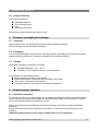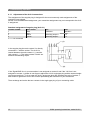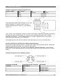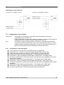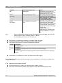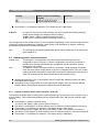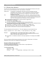
1
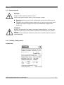
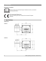
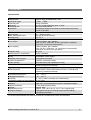
Operating instructions
Attachable indicator, model A-AI-2
GB
F
14014118.01 • V2.0 • 03/2011
Attachable indicator, model A-AI-2
GB
Operating instructions, model A-AI-2
Page
1 - 28
© 2010 WIKA Alexander Wiegand SE & Co. KG
All rights reserved.
WIKA® is a registered trademark in various countries.
Prior to starting any work, read the operating instructions!
Keep for later use!
2
WIKA operating instructions, model A-AI-2
Contents
1
2
General information .................................................................................................................... 4
Safety........................................................................................................................................... 5
2.1
2.2
2.3
2.4
3
4
Specifications ............................................................................................................................. 8
Design and function ................................................................................................................. 10
4.1
4.2
5
Electrical connection ............................................................................................................ 11
Configuration of the indicator ............................................................................................... 15
Switching points / alarm boundaries .................................................................................... 18
Offset and slope adjustment ................................................................................................ 21
Min-/max-value storage ....................................................................................................... 22
Maintenance and cleaning ....................................................................................................... 22
7.1
7.2
8
9
Transport ............................................................................................................................. 11
Packaging............................................................................................................................ 11
Storage ................................................................................................................................ 11
Commissoning, operation ........................................................................................................ 11
6.1
6.2
6.3
6.4
6.5
7
Description .......................................................................................................................... 10
Scope of delivery ................................................................................................................. 11
Transport, packaging and storage .......................................................................................... 11
5.1
5.2
5.3
6
Intended use .......................................................................................................................... 5
Personnel qualification........................................................................................................... 6
Special hazards ..................................................................................................................... 7
Labelling / Safety marks ........................................................................................................ 7
Maintenance ........................................................................................................................ 22
Cleaning .............................................................................................................................. 22
Faults ......................................................................................................................................... 23
Dismounting, return and disposal ........................................................................................... 24
9.1
9.2
9.3
Demontage .......................................................................................................................... 24
Return.................................................................................................................................. 24
Disposal............................................................................................................................... 24
10 Appendix ................................................................................................................................... 25
Declarations of conformity can be found online at www.wika.com.
WIKA operating instructions, model A-AI-2
3
1 General information
1 General information
The instrument described in the operating instructions has been designed and manufactured
using state-of-the-art technology.
All components are subject to stringent quality and environmental criteria during production.
Our management systems are certified to ISO 9001 and ISO 14001.
These operating instructions contain important information on handling the instrument. Working
safely requires that all safety instructions and work instructions are observed.
Observe the relevant local accident prevention regulations and general safety regulations for
the instrument's range of use.
The operating instructions are part of the instrument and must be kept in the immediate vicinity
of the instrument and readily accessible to skilled personnel at any time.
Skilled personnel must have carefully read and understood the operating instructions, prior to
beginning any work.
The manufacturer's liability is void in the case of any damage caused by using the product
contrary to its intended use, non-compliance with these operating instructions, assignment of
insufficiently qualified skilled personnel or unauthorised modifications to the instrument.
The general terms and conditions, contained in the sales documentation, shall apply.
Subject to technical modifications.
Further information:
- Internet address:
- Relevant data sheet:
- Application consultant:
4
www.wika.de / www.wika.com
AC 80.08
Tel.: (+49) 9372/132-0
Fax: (+49) 9372/132-406
E-Mail: [email protected]
WIKA operating instructions, model A-AI-2
2 Safety
Explanation of symbols
WARNING!
... indicates a potentially dangerous situation that can result in serious injury or
death, if not avoided.
Information
... points out useful tips, recommendations and information for efficient and troublefree operation.
DANGER!
...identifies hazards caused by electric power. Should the safety instructions not be
observed, there is a risk of serious or fatal injury.
2 Safety
WARNING!
Before installation, commissioning and operation, ensure that the appropriate
instrument has been selected in terms of measuring range, design and specific
measuring conditions.
Non-observance can result in serious injury and/or damage to equipment.
Further important safety instructions can be found in the individual chapters of these
operating instructions.
2.1
Intended use
The attachable indicator A-AI-2 is used for attaching between a transmitter and the according angular
plug.
The instrument has been designed and built solely for the intended use described here, and may only
be used accordingly.
If the instrument is transported from a cold into a warm environment, the formation of condensation
may result in the instrument malfunctioning. Before putting it back into operation, wait for the
instrument temperature and the room temperature to equalise.
The manufacturer shall not be liable for claims of any type based on operation contrary to the intended
use.
WIKA operating instructions, model A-AI-2
5
2 Safety
This device was designed and tested considering the safety regulations for electronic measuring
devices.
Faultless operation and reliability in operation of the measuring device can only be assured if the
General Safety Measures and the devices specific safety regulation, mentioned in this operating
instructions, are considered.
1. Faultless operation and reliability in operation of the measuring device can only be assured if
the device is used within the climatic conditions specified in the chapter “Specifications“.
2. Always disconnect the device from its supply before opening it. Take care that nobody can
touch any of the unit‘s contacts after installing the device.
3. Standard regulations for operation and safety for electrical, light and heavy current equipment
have to be observed, with particular attention paid to the national safety regulations (e.g. VDE
0100).
4. When connecting the device to other devices (e.g. the PC) the interconnection has to be
designed most thoroughly, as internal connections in third-party devices (e.g. connection of
ground with protective earth) may lead to unwanted voltage potentials.
5. The device must be switched off and must be marked against using again, in case of obvious
malfunctions of the device which are e.g.:
visible damage
no prescripted working of the device
storing the device under inappropriate conditions for longer time
When not sure, the device should be sent to the manufacturer for repairing or servicing.
6. In case of connecting lines longer than 30 m or in case of lines leaving the building an
additional suitable overvoltage protection shall be provided.
2.2
Personnel qualification
WARNING!
Risk of injury should qualification be insufficient!
Improper handling can result in considerable injury and damage to equipment.
The activities described in these operating instructions may only be carried out
by skilled personnel who have the qualifications described below.
Keep unqualified personnel away from hazardous areas.
Skilled electrical personnel
Skilled electrical personnel are understood to be personnel who, based on their technical training,
knowledge of measurement and control technology and on their experience and knowledge of
country-specific regulations, current standards and directives, are capable of carrying out work on
electrical systems and independently recognizing and avoiding potential hazards.
The skilled electrical personnel have been specifically trained for the work environment they are
working in and know the relevant standards and regulations.
The skilled electrical personnel must comply with current legal accident prevention regulations.
6
WIKA operating instructions, model A-AI-2
2 Safety
2.3
Special hazards
DANGER!
Danger of death caused by electric current.
Upon contact with live parts, there is a direct danger of death.
Electrical instruments may only be installed and mounted by skilled electrical
personnel.
Operation using a defective power supply unit (e.g. short circuit from the mains
voltage to the output voltage) can result in life-threatening voltages at the
instrument!
WARNING!
Do NOT use this product as safety or emergency stopping device, or in any other
application where failure of the product could result in personal injury or material
damage.
Failure to comply with these instructions could result in death or serious injury and
material damage.
2.4
Labelling / Safety marks
Product label
WIKA operating instructions, model A-AI-2
7
3 Specifications
Explanation of symbols
Before mounting and commissioning the instrument, ensure you read the
operating instructions!
CE, Communauté Européenne
Instruments bearing this mark comply with the relevant European
directives.
3 Specifications
Dimensions
A-AI-2-1:
A-AI-2-S:
8
WIKA operating instructions, model A-AI-2
3 Specifications
Specifications
Display
■Actual value
■Indication range
■Decimal point
■Accuracy
■Sampling rate
■Operation
Input
■Input signal
■Max. permissible input
■Voltage drop
Switching output
■One output
■{two outputs}
■Reaction time
■switching point / hysteresise
Equipment
■Filter
■Min/Max value memory
■Control characteristic
■Alarm function
Electrical connection
CE-conformity
■EMC directives
Permissible
■Operating temperature
■Storage temperature
■Humidity
Temperature effect on the indication
Case
■Material
■Ingress protection
■Weight
■Dimensions in mm
■Scope of delivery
LED, 4 -digit, character size 7 mm
-1999 ... +9999
freely selectable
± 0.2 % of the measuring span ± 1 digit
50 measurements/sec
membrane keypad on the front or push-buttons behind the
cover of the case
4 … 20 mA (2-wire)
25 mA (40 mA short term)
DC 5.5 V
Open Collector, galv. isolated,
max. DC 28 V, load max. 20 mA, connection via angular
connector, no short-circuit protection
Open Collector, galv. isolated,
max. DC 28 V, load max. 1 A, connection via female M8connector, no short-circuit protection
≤ 20 ms
freely selectable
activatable, 3 filter stages
retrievable via keypad
ON/OFF (two-point control)
Min-/Max alarm with settable time delay
to transmitter with 4 ... 20 mA and angular connector to DIN
43650, polarity-free mounting
2004/108/EG, EN 61326 Emission (Group 1, Class B) and
Immunity (industrial locations)
-25 ... +50 °C
-30 ... +85 °C
0 ... 80 % relative humidity (no condensation)
0.1% / 10 K
ABS case, polycarbonate front panel, membrane keypad
IP 65 (when properly fitted)
approx. 80 g
approx. 50.5 x 90 x 39.5 (L x B x T) incl. angular plug
Attachable indicator, mounting screws, profile sealing,
operating instructions
For further specifications see WIKA data sheet AC 80.08 and the order documentation.
WIKA operating instructions, model A-AI-2
9
4 Design and function
4 Design and function
4.1
Description
The attachable indicator A-AI-2 is a microprocessor controlled displaying, monitoring and controlling
device. In accordance to his type the device is supporting an input for standard signal 4…20 mA .
The device is available in two different versions. In the given operating instructions both versions are
described. If there is nothing other montioned, the declarations are for both versions.
version
A-AI-2-1
A-AI-2-S
Order code
A-AI-2-AA1TB-Z
A-AI-2-AASTB-Z
version A-AI-2-1 (standard)
In according to his type the device is
supporting an input for standard
signals 4…20 mA. The device
features one switching output (npnoutput), which can be configured as
2-point-controller or min/max alarm
output. The state of the switching
output is displayed with the LED left
beneath the LED-display.
version A-AI-2-S (optional)
The device features two switching
outputs (npn-output), which can be
configured as 2-point-controller, 3point-controller, 2-point-controller with
min./max.alarm or min./max. alarm
output (common or individual). The
state of the switching outputs is
displayed with 2 LED beneath the
LED-display. The left LED indicates
the state of the 1st output and the right
LED the state of the 2nd output.
When leaving our factory the A-AI-2 has been subjected to various inspection tests and is completely
calibrated.
Before the A-AI-2 can be used, it has to be configured for the customer’s application.
10
WIKA operating instructions, model A-AI-2
6 Commissoning, operation
4.2
Scope of delivery
The scope of delivery is:
Attachable indicator
Two mounting screws
Seal
Operating instructions
Cross-check scope of delivery with delivery note.
5 Transport, packaging and storage
5.1
Transport
Check instrument for any damage that may have been caused by transport.
Obvious damage must be reported immediately.
5.2
Packaging
Do not remove packaging until just before mounting. Keep the packaging as it will provide optimum
protection during transport (e.g. change in installation site, sending for repair).
5.3
Storage
Permissible conditions at the place of storage:
Storage temperature: -30…+85 °C
Humidity: 0...80 % relative humidity (no condensation)
Avoid exposure to the following factors:
Direct sunlight or proximity to hot objects
Mechanical vibration, mechanical shock (putting it down hard)
Soot, vapour, dust and corrosive gases
Potentially explosive environments, flammable atmospheres
6 Commissoning, operation
6.1
Electrical connection
To connect the A-AI-2 it is simply plugged into an existing transmitter by means of a special adapter
for the cubic plug according to DIN 43650. An additional power supply is not necessary , because
device takes power directly from measuring current.
Electric connection and commissioning of the device must be carried out by trained and skilled
personnel.
Wrong connection may lead to destruction of the device, in which case we cannot assume any
warranty.
! Mind the maximum input current rating of 40mA under any circumstances!
WIKA operating instructions, model A-AI-2
11
6 Commissoning, operation
6.1.1
Adjustment of the A-AI-2 connections
The assignment of the angular plug is designed for the most commonly used assignments of the
respective input signals.
As this is not a standardized assignment, your transmitter assignment may not correspond to the A-AI2 assignment.
Standard assignment of angular plug (A-AI-2-1)
contact number
wire colour
1
blue
2
red
3
black
4
yellow
n.c. = not connected
pin
indicator +
jack
indicator connected
switching output +
n.c.
switching output n.c.
In the angular plug the male contact 2 is directly
connected 1:1 with the socket. The A-AI-2 is
located between the male contact 1 (+) and the
jack contact 1 (-). The male contacts 3 and 4 are
used for the switching output.
If the 'Signal/GND'-line in your transmitter is not assigned to contact 2 and if the '-Ub'-line is not
assigned to contact 1, please do not forget to adjust the A-AI-2 angle-type plug and the external angletype plug accordingly. To do so open the A-AI-2 angle-type plug and exchange the wire of contact 1
and contact 2 against the wire of the contact representing the connection in your transmitter.
Then exchange and rewire the two contacts in the angle-type plug of your connecting cable.
12
WIKA operating instructions, model A-AI-2
6 Commissoning, operation
Standard assignment of angular plug (A-AI-2-S)
contact number
wire colour
pin
1
blue
indicator +
2
red
3
black
4
yellow
jack
indicator connected
connected
connected
In the angle-type plug the male contacts 2, 3 and 4 are
directly connected 1:1 with the socket. Device is
located between the male contact 1 (+) and the jack
contact 1 (-).
If the '-Ub'-line is not assigned to contact 1, please do not forget to adjust the angle-type plug and the
external angle-type plug accordingly: To do so open the angle-type plug (refer to the “general
instructions for change ....”) and exchange the wire of contact 1 against the wire of the contact
representing the connection in your transmitter.
Then exchange and rewire the two contacts in the angle-type plug of your connecting cable.
General instruction for change of the angular plug assignment
Remove the coupling insert by means of a screw driver at the position indicated (arrow). Change the
assignment according the notes of the respective input signal.
Latch coupling insert in cover. You have a choice between 4 different orientations – each of them
spaced 90°. Put on angel-type plug and connect plugs using the long screw delivered (do not forget
seals).
Terminal assignment of the switching outputs
assignment of the M8connector
1
2
3
4
assignment of the connection
cable EBK401
brown
white
blue
black
WIKA operating instructions, model A-AI-2
description
switching output 1 switching output 1 +
switching output 2 switching output 2 +
13
6 Commissoning, operation
6.1.2
Connection example
Please take care that you must not exceed the limits of the voltage and of the maximum current
of the switching outputs (not even for a short period of time).
Please take extreme care when switching inductive loads (like coils or relays, etc.) because of their
high voltage peaks, protective measures to limit these peaks have to be taken.
When switching large capacitive loads a series resistor for current limitation needed, because of the
high turn-on-current of high capacitive loads. The same applies to incandescent lamps, whose turnon-current is also quite high due to their low cold resistance.
Connecting to current loop and switching of a relay (A-AI-2-1)
combined power supply for measurement section
and output section
separate power supply for measurement section and
output section
Connecting to current loop (A-AI-2-S)
14
WIKA operating instructions, model A-AI-2
6 Commissoning, operation
Switching of a relay (A-AI-2-S)
connection as „LowSide“ contactor
6.2
Configuration of the indicator
Please note:
Hint:
6.2.1
connection as „HighSide“ contactor
The storage of a configuration value will be done by switching to the next
configuration value (via button 1).
When configuration is active and no button is pressed for more than 60 seconds the
configuration will be cancelled. Stored changes will not be lost!
The buttons 2 and 3 are featured with a ‘roll-function‘. When pressing the button
once the value will be raised (button 2) by one or lowered (button 3) by one. When
holding the button pressed for longer than 1 second the value starts counting up or
down, the counting speed will be raised after a short period of time.
Configuration of the input signal
Turn the device on and wait until it completed its built-in segment test.
Press button 2 for 1 second, in the device display appears ‚dP’ (decimal point).
Select the desired decimal point place by pressing button 2 respective button 3.
Validate the selected value by pressing button 1. The display shows ‚dP’ again.
Press button 1 again, the display will show “di.Lo“ (Display Low = low display value).
Use button 2 and button 3 to select the desired value the device should display when a 4mA
input signal is attached.
Validate the selected value by pressing button 1. The display shows “di.Lo“ again.
Press button 1 again, the display will show “di.Hi“ (Display High = high display value).
Use button 2 and button 3 to select the desired value the device should display when a 20mA
is attached.
Validate the selected value by pressing button 1. The display shows “di.Hi“ again.
Press button 1 again. The display will show “Li“ (Limit = Measuring range limit).
Use button 2 and button 3 to select the desired measuring range limit.
WIKA operating instructions, model A-AI-2
15
6 Commissoning, operation
Hint:
display
off
measuring range input
deactivated
on.Er
(on error)
active, (displays an error)
on.rG
(on range)
aktiv, (displays the selected
limit)
notes
Exceeding of the measuring
range limit is tolerable as of the
measuring limit (p.r.t. hint).
The meas. range limit is exactly
bounded by the input signal.
When exceeding or undercutting
the input signal an error
message will be displayed.
The meas. range limit is exactly
bounded by the input signal.
When exceeding or undercutting
the input signal the device will
display the selected lower/upper
display value.
[e.g. humidity: when
undercutting or exceeding, the
device will display 0 % or 100
%]
When exceeding the measuring limit independently from the setting, the device will
always display an error message (“Err.1“ or “Err.2“).
The measuring limits are by 3.7 and 20.8 mA .
Press button 1 to validate the selection, the display shows “Li“ again.
When pressing button 1 again, the display will show “FiLt“ (Filter).
Use button 2 and button 3 to select the desired filter behavior
display description
0
filter deactivated
1
filter stage 1:
suppresses jumping display values caused be smallest changes
2
filter stage 2:
additional suppression of measuring peaks (causes delayed reaction of switching
output)
Press button 1 to validate your value, the display shows “FiLt“ again.
The configuration of the device to the input signal is now completed. You now have to configure the
output of the device.
6.2.2
Selection of the output function
When pressing button 1 again, the display will show “outP“. (Output)
Use button 2 and button 3 (middle or right button) to select the desired output-function.
16
WIKA operating instructions, model A-AI-2
6 Commissoning, operation
A-AI-2-1:
description
no output, device is
used as display
2-point-controller
Min/Max alarm
to select as
output
no
output (out)
see chapter
off
--
2P
AL
switching function
min/max alarm, inverse
6.3.1
6.3.2
to select as
output
no
output 1 (out 1)
output 2 (out 2)
see chapter
off
off
--
2P
switching
function
Min-/Max-alarm,
inverted
switching
function 1
switching
function 1
Max alarm,
inverted
off
6.3.1
off
6.3.2
switching
function 2
Min/Max alarm,
inverted
Min alarm,
inverted
6.3.1
A-AI-2-S:
description
no output, device is
used as display
2-point-controller
Min-/Max-alarm,
common
3-point-controller
AL
2-Punkt-Regler with
Min-/Max-alarm
Min-/Max-Alarm,
individual
2P.AL
3P
AL.F2
6.3.1
6.3.2
Press button 1 to validate the selected output function. The display shows “outP“ again.
For output function = no the configuration is now finished. Press button 1 to finish the adjustment and
to switch over to display the measuring value.
If the output function was changed here, the delay and preferred state of switching function and the
switching points / alarm-boundaries are to configured in following.
Hint:
The settings described in the following depend on the selected output function.
Depending on this setting therefore it is possible that more than one point is not
present in the following.
When pressing button 1 again, the device will display “1.dEL“ (delay = delay of switching
function 1).
Use button 2 and button 3 to set the desired value for the switching-delay.
Hint: the selected value [0.01 ... 2.00] accords the switching delay in seconds.
Press button 1 to validate the selection. The display shows “1.dEL“ again.
When pressing button 1 again, the device will display “1.Err“ (error = preferred state of
switching function 1).
Use button 2 and button 3 to set the desired initial state in case of an error.
WIKA operating instructions, model A-AI-2
17
6 Commissoning, operation
display
off
on
preferred state of switching
function
Inactive in case of an error
Active in case of an error
comment
---
Press button 1 to validate the selection. The display shows “1.Err“ again.
A-AI-2-S:
In case you selected a 3-point-controlle you have to make the following settings
similar to the settings you already made for output 1:
“2.dEL“ (delay = delay of switching function 2) and
“2.Err“ (error = preferred state of switching function 2).
The configuration of the output function is now completed. Depending on the selected output function
you have to make the settings for switching / alarm points. See description in chapter „switching
points/alarm-boundaries“ for further information.
Hint:
6.3
The settings for the switching and alarm points can be made later in an extra menu
(see chapter 6.3)
Switching points / alarm boundaries
Please note:
Hint:
The storage of a configuration value will be done by switching to the next
configuration value (via button 1). When configuration is active and no button is
pressed for more than 60 seconds the configuration will be cancelled. Stored
changes will not be lost!
The buttons 2 and 3 are featured with a ‘roll-function‘. When pressing the button
once the value will be raised (button 2) by one or lowered (button 3) by one. When
holding the button pressed for longer than 1 second the value starts counting up or
down, the counting speed will be raised after a short period of time.
When pressing button 1 for >2 seconds the menu to select the switching points and alarmboundaries will be called.
Depending on the configuration you have made in the „output“ menu you will get different
display values. Please follow the specific chapter for further information.
6.3.1
2-point-controller (and 3-point-controller: A-AI-2-S)
This chapter describes how to configure the switching points as use the device for a 2-point- resp. 3point-controller. This instruction demands that you selected “2P“ resp. “3P“ as your desired output
function.
Press button 1 (when not already done).
The device will display “1.on“ (turn-on-point of output 1)
Use button 2 and button 3 to set the desired value, the device’s output should be turning on.
Press button 1 to validate your selection. The display shows “1.on“ again.
When pressing button 1 again, the device will display “1.off“. (turn-off-point out output 1)
Use button 2 and button 3 to set the desired value, the device’s output 1 should be turning off.
Press button 1 to validate your selection. The display shows “1.off“again.
18
WIKA operating instructions, model A-AI-2
6 Commissoning, operation
Example:
You want to control the temperature of a heating coil, with a hysteresis of +2°C, to
120°C. Therefore you will have to select the turn-on-point “1.on“ to 120°C and the
turn-off-point to “122°C“.
=> When your heating coil temperature falls below 120°C it will be turned on. When
the temperature rises above 122°C the heating coil will be turned off.
Note: Depending on the inertia of your heating coil an overshooting of the
temperature may be possible.
A-AI-2-S:
When selected '2-point-controller' you finished configuring your device. Press button
1 to switch over to display the measuring value.
When selected '3-point-controller' you have to make the following settings similar to
the settings you already made for output 1:
“2.on“ (turn-on-point of output 2) and
“2.off“ (turn-off-point out output 2)
Now you finished configuring the switching point adjustment of your device. Press button 1 to finish
the adjustment and to switch over to display the measuring value
6.3.2
Min-/Max-Alarm (A-AI-2-1)
Min-/Max-Alarm (common or individual) (A-AI-2-S)
This chapter describes how to configure the device‘s alarm boundaries for min-/max-alarm-monitoring.
This instruction demands that you selected “AL“ (or “AL.2F” for A-AI-2-S) as your desired output
function.
Press button 1 (when not already done) , the device will display “AL.Hi“. (maximum alarmvalue)
Use button 2 and button 3 to set the desired value, the device should turn on its maximumalarm.
Press button 1 to validate your selection. The display shows “AL.Hi“ again.
When pressing button 1 again, the device will display “AL.Lo“. (minimum alarm-value)
Use button 2 and button 3 to set the desired value, the device should turn on its minimumalarm
Press button 1 to validate your selection. The display shows “AL.Lo“ again.
When pressing button 1 again, the device will display “A.dEL“. (delay of the alarm-function)
Use button 2 and button 3 to set the desired delay of the alarm-function.
Note: the selected value [0 ... 9999] accords the alarm delay in seconds.
The device will turn on the alarm after minimum or maximum alarm value was active for the
delay-time you have set.
Press button 1 to validate the delay time. The display shows “A.dEL“ again.
Example:
You want to have a temperature alarm-monitoring of a greenhouse. The alarm
should start when the temperature rises above 50 °C or falls below 15 °C. Therefore
your settings will be 50 °C for the maximum alarm-value “AL.HI“ and 15 °C for the
minimum alarm-value “AL.Lo“.
=> The alarm will be starting after the temperature rises above 50 °C and stays
above 50 °C for the entered delay time or after it had been falling below 15 °C and
stays below 15 °C for the entered delay time.
Please note that the alarm-outputs are inverted! This means, that the output will be active when there
is no alarm!
WIKA operating instructions, model A-AI-2
19
6 Commissoning, operation
Now you finished configuring the alarm adjustment of your device. Press button 1 to finish the
adjustment and to switch over to display the measuring value.
6.3.3
2-point-controller with min-/max-alarm (A-AI-2-S)
This chapter describes how to configure the switching points as use the device for a 2-point-controller
with min-/max-alarm. This instruction demands that you selected “2P.AL“ as your desired output
function.
Press button 1 (when not already done).
The device will display “1.on“ (turn-on-point of output 1)
Use button 2 and button 3 to set the desired value, the device’s output should be turning on.
Press button 1 to validate your selection. The display shows “1.on“ again.
When pressing button 1 again, the device will display “1.off“. (turn-off-point out output 1)
Use button 2 and button 3 to set the desired value, the device’s output 1 should be turning off.
Press button 1 to validate your selection. The display shows “1.off“again.
When pressing button 1 again, the device will display “AL.Hi“. (maximum alarm-value)
Use button 2 and button 3 to set the desired value, the device should turn on its maximumalarm.
Press button 1 to validate your selection. The display shows “AL.Hi“ again.
When pressing button 1 again, the device will display “AL.Lo“. (minimum alarm-value)
Use button 2 and button 3 to set the desired value, the device should turn on its minimumalarm
Press button 1 to validate your selection. The display shows “AL.Lo“ again.
When pressing button 1 again, the device will display “A.dEL“. (delay of the alarm-function)
Use button 2 and button 3 to set the desired delay of the alarm-function.
Note: the selected value [0 ... 9999] accords the alarm delay in seconds.
The device will turn on the alarm after minimum or maximum alarm value was active for the
delay-time you have set.
Press button 1 to validate the delay time. The display shows “A.dEL“ again.
Please note that the alarm-outputs are inverted! This means, that the output will be active when there
is no alarm!
Now you finished configuring the switching point and the alarm adjustment of your device. Press
button 1 to finish the adjustment and to switch over to display the measuring value.
20
WIKA operating instructions, model A-AI-2
6 Commissoning, operation
6.4
Offset and slope adjustment
The offset and slope-adjustment function can be used for compensating the tolerance of the used
sensor, resp. for vernier adjustment of the used transducer / transmitter.
Please note:
Hint:
The storage of a configuration value will be occur by switching to the next
configuration value (via button 1). When configuration is active and no button is
pressed for more than 60 seconds the configuration will be cancelled. Stored
changes will not be lost!
The buttons 2 and 3 are featured with a ‘roll-function‘. When pressing the button
once the value will be raised (button 2) by one or lowered (button 3) by one. When
holding the button pressed for longer than 1 second the value starts counting up or
down, the counting speed will be raised after a short period of time.
Turn on the device and wait after it finished its built-in segment test.
Press button 3 > 2 seconds
The device will display “OFFS“ (Offset).
Use button 2 and button 3 for setting the desired zero point offset-value.
The input of the offset value is in digit. The value that had been set will be subtracted from the
measured value. (see below for further information)
Press button 1 to validate your selection. The display shows “OFFS“ again.
When pressing button 1 again, the device will display “SCAL“. (scale = slope)
Use button 2 and button 3 to select the desired slope-adjustment.
The slope adjustment will be entered in %. The value displayed can be calculated like this:
Display = (measured value – offset – di.Lo) * (1 + slope adjustment [% / 100] ) + di.Lo
Example:
The setting is 2.00 => the slope has risen 2.00 % => slope = 102%.
When measuring a value of 1000 (without slope-adjustment) the device would
display 1020 (with slope adjustment of 102 %)
Press button 1 to validate the selection of the slope-adjustment. The display shows “SCAL“
again.
Now you finished the offset and slope adjustment of your device. Press button 1 to finish the
adjustment and to switch over to display the measuring value.
Example for Offset and slope adjustment
Connecting of a pressure-transducer
The device displays the following values (without offset- or slope-adjustment):
0.08 at 0.00 bar and 20.02 at 20.00 bar
Therefore you calculated:
zero point:
0.08
slope: 20.02 – 0.08 = 19.94
deviation:
0.06
(= target-slope – actual-slope = 20.00 - 19.94)
WIKA operating instructions, model A-AI-2
21
7 Maintenance and cleaning
You have to set:
offset =
scale =
6.5
0.08
0.30
(= zero point-deviation)
(= deviation/actual-slope=0.06/9.94=0.0030= 0.30%)
Min-/max-value storage
The device features a minimum/maximum-value storage. In this storage the highest and lowest
performance data is saved. The storage is non-permanent so the saved values get lost in case of
voltage drop.
Calling of the minimum-value
press button 3 shortly
Calling of the maximum-value
press button 2 shortly
Erasing of the min/max values
press button 2 and 3 for 2 sec.
the device will display “Lo“
briefly, after that the min-value is
displayed for about 2 sec
the device will display “Hi“
briefly, after that the max-value
is displayed for about 2 sec.
The device will display “CLr“
briefly, after that the min/maxvalues are set to the cur-rent
displayed value.
7 Maintenance and cleaning
7.1
Maintenance
This instrument is maintenance-free.
Repairs must only be carried out by the manufacturer.
7.2
Cleaning
CAUTION!
Before cleaning, correctly disconnect the instrument from the mains.
Clean the instrument with a moist cloth.
Electrical connections must not come into contact with moisture.
For information on returning the instrument see chapter "9.2 Return".
22
WIKA operating instructions, model A-AI-2
8 Faults
8 Faults
When detecting an operating state which is not permissible, the device will display an error code. The
following error codes are defined:
Fehler
Err.1
Exceeding of the measuring
range
presumed cause
Input signal too high
Sensor shorted
Err.2
values below measuring range
Input signal zu low
Current below 4 mA
Err.3
display range has been
exceeded
incorrect scale
Err.4
values below display range
incorrect scale
Err.7
System error
valid operation temperature
has been exceeded
defective device
Err.11
value could not be calculated
incorrect scale
solution
The input signal must be
within the limits
Check sensor,
transducer/transmitter
Check device configuration
The input signal must be
within the limits
Check sensor,
transducer/transmitter
Check device configuration
The input signal must be
within the limits
scale smaller indication
range
The input signal must be
within the limits
scale smaller indication
range
Stay within valid temperature
range
Exchange the defective
device
Check settings and input
signals
CAUTION!
If faults cannot be eliminated by means of the measures listed above, the instrument
must be shut down immediately, and it must be ensured that pressure and/or signal
are no longer present, and it must be prevented from being inadvertently put back
into service. In this case, contact the manufacturer.
If a return is needed, please follow the instructions given in chapter "9.2 Return".
WIKA operating instructions, model A-AI-2
23
9 Dismounting, return and disposal
9 Dismounting, return and disposal
WARNING!
Residual media in dismounted instruments can result in a risk to persons,
the environment and equipment. Take sufficient precautionary measures.
9.1
Demontage
First disconnect power supply, than open the screw which connects angular plug, indicator and
transmitter. Remove angular plug and indicator. After this attach the angular plug to transmitter and
fasten the screw. Please use the screw which is from the scope of delivery of the transmitter. This
screw is smaller.
9.2
Return
WARNING!
Strictly observe when shipping the instrument:
All instruments delivered to WIKA must be free from any kind of hazardous
substances (acids, bases, solutions, etc.).
When returning the instrument, use the original packaging or a suitable transport package.
Enclose the completed return form with the instrument.
The return form is available on the internet:
www.wika.de / Service / Return
9.3
Disposal
Incorrect disposal can put the environment at risk.
Dispose of instrument components and packaging materials in an environmentally
compatible way and in accordance with the country-specific waste disposal regulations.
24
WIKA operating instructions, model A-AI-2
10 Appendix
10 Appendix
WIKA operating instructions, model A-AI-2
25
10 Appendix
26
WIKA operating instructions, model A-AI-2
10 Appendix
WIKA operating instructions, model A-AI-2
27
WIKA global
WIKA subsidiaries worldwide can be found online at www.wika.com.
WIKA Alexander Wiegand SE & Co. KG
Alexander-Wiegand-Straße 30
63911 Klingenberg • Germany
Tel. (+49) 9372/132-0
Fax (+49) 9372/132-406
E-Mail [email protected]
www.wika.de
28
WIKA operating instructions, model A-AI-2