1
Operating Instructions
CPS 300
ELECTRONIC GMBH
Ernst-Zimmermann-Str. 18
D-88045 Friedrichshafen
Telefon 07541 / 6000-0
Telefax 07541 / 6000-11
DocuNo: 040.001.02
Date: February 2001
Operating Instructions CPS300
I
1. CPS 300 overall view...................................................................1
2. Operating modes.........................................................................2
2.1 Main menue / operating mode selection.........................................................................2
3. Control elements (display and keyboard) .................................3
3.1
3.2
3.3
3.4
Display ..........................................................................................................................3
Keyboard .......................................................................................................................3
Value input ....................................................................................................................3
Keyboard functions........................................................................................................4
4. Program memory ........................................................................4
5. Operating modes.........................................................................5
5.1 Automatic mode ............................................................................................................5
5.1.1 Program number and quantity setting.....................................................................5
5.1.2 Releasing program for execution............................................................................5
5.1.3 Initiating and interrupting program flow...................................................................6
5.1.4 Values displayed during program execution ...........................................................6
5.2 Manual mode.................................................................................................................7
5.2.1 Standard functions in manual mode .......................................................................7
5.2.2 Driving to a certain position....................................................................................8
5.2.3 Teach-In ................................................................................................................8
5.3 Reference run................................................................................................................9
5.3.1 General information ...............................................................................................9
5.3.2 Calling possibilities.................................................................................................9
5.3.3 Reference shaft encoder types.............................................................................10
5.4 Program input..............................................................................................................10
5.4.1 Program selection ................................................................................................10
5.4.2 Key functions .......................................................................................................10
5.4.3 Processing records (command menue 1) .............................................................11
5.4.3.1 "STOP" and "Following-on record"................................................................11
5.4.4 Program processing (command menue 2)............................................................12
5.4.5 General processing (command menue 3).............................................................13
5.5 Parameter input ...........................................................................................................14
5.5.1 Password request, general password....................................................................14
5.5.2 Parameter menue ................................................................................................14
5.5.3 Key functions .......................................................................................................14
5.6 Card reader .................................................................................................................15
6. Programming.............................................................................16
6.1 Record type selection ..................................................................................................16
6.2 Positioning commands.................................................................................................16
6.2.1 Record type "Positioning".....................................................................................16
6.2.2 Record type "Position / Speed-display".................................................................17
6.3 Record type "Machine function" ...................................................................................18
6.4 Reference run and setting 0.........................................................................................19
6.4.1 Record type "Reference run"................................................................................19
6.4.2 Record type "Setting axles 0" ...............................................................................19
6.5 Control commands ......................................................................................................20
II
Operating Instructions CPS300
6.5.1 Record type "Jump" .............................................................................................20
6.5.2 Record typ "Loop" ................................................................................................20
6.5.3 Record type "Programm call" ...............................................................................21
6.5.4 Record type "Dwell time"......................................................................................21
6.6 Record type "Input"......................................................................................................22
7. Error management ....................................................................23
7.1 Possibilities to continue function after errors ................................................................23
7.2 External error acknowledgment ...................................................................................23
8. Error messages .........................................................................24
8.1 Causes ........................................................................................................................25
9. Parameter data ..........................................................................27
9.1 Parameter group "Controller data" ...............................................................................27
9.2 Parameter group "Machine data" .................................................................................28
9.3 Parameter group "Speeds" ..........................................................................................29
9.4 Parameter group "Reference run" ................................................................................30
9.5 Parameter group "Passwords" .....................................................................................30
9.6 Parameters with access via level 0..............................................................................31
9.7 Parameters with access via level 1..............................................................................31
9.8 Parameters with access via level 2..............................................................................31
9.9 Parameters with access via level 3..............................................................................31
9.10 Example of calculation ................................................................................................32
10. Inputs and Outputs ...................................................................33
10.1 Digital inputs................................................................................................................33
10.2 Digital outputs..............................................................................................................34
10.2.1 Connection digital outputs (e.g. Machine functions)..............................................34
10.3 Technical data inputs and outputs................................................................................35
11. Technical data controller..........................................................36
12. Options.......................................................................................37
13. Precautions................................................................................37
Operating Instructions CPS300
1
1. CPS 300 overall view
• Advanced CNC positioning control used for single-axis or multiaxis applications.
• Easy and menue-guided operation and programming. Knowledge of a programming
language is not requested.
• Easy and comfortable input due to decoded text display and well arranged
keyboard. No multiple key assignment.
• Compact unit comprising controllers as well as position control and operating
element.
• Password protected parameter input as decoded text ensures easy adaptation to
drives and machines.
• Sinusoidal acceleration curves considerably reduce the load of the mechanical
components.
• Use of highly dynamic drives due to short control cycle times.
• Automatic diagnosis with decoded text display.
2
Operating Instructions CPS300
2. Operating modes
§ Different operating modes are available to ensure all necessary functions.
§ Menue-guided calling by means of the controller.
§ If necessary, all operating modes can be disabled.
Operating mode
Automatic
- single step
- cycle run
- continuous run
Manual mode
Reference run
Program input
Parameter input
Card reader
Function
Execution of program sequences
step by step operation
complete program run
contiguous program repetition
Move axles in manual mode
rapid motion, creep speed
approach starting position
set zero point
reference run
teach-in
Automatic search for the machine
reference point.
Variant setting and programming by
parameters.
Menue- And mask-guided program
generation.
Record-by-record input
Program processing functions
Setting of machine-, controller- and
user-specific auxiliary values
Parameter and program storage
2.1 Main menue / operating mode selection
§
§
§
§
ensures the operating mode selection
selection by function key
disabled operating modes are not displayed
only possible if no operating mode and no error message are active
F1: Automatic
F2: Manual mode
F3: Reference
ABC
DE@
F4: Program input
F5: Parameter input
C : Card reader
The respective operating mode is initiated.
Operating Instructions CPS300
3
3. Control elements (display and keyboard)
1:> status informationen
2:> input and display field
3:> input and display field
4:> functions of keys F1 to F5
2
3
4
5
6
7
8
9
0
.
F2
F3
F4
F5
C
field
up
page
down
page
up
menu/
end
+-
F1
field
down
1
function keys
clear
enter
change sign
3.1 Display
§
§
§
§
§
§
LCD display
Decoded text
Top line: status information
Middle lines: inputs and outputs
Bottom line: function key assignment depending on operating mode
In some places, option menues displayed on one complete page
3.2 Keyboard
§
§
§
§
*
Membrane keyboard with tactile acknowledgement (click point)
Numeral key block for input
Function key block for operation
Uniform functions in all operating modes
3.3 Value input
§ Inputs are immediately stored without striking another key.
§ Limit monitoring
§ Input routines avoid unnecessary key striking
4
Operating Instructions CPS300
3.4 Keyboard functions
+
.
@
Q
>
<
}
{
X
A E
Change of sign
Decimal point
Erase input field
Acknowledge input and jump to next input field,
switch to next input mask after last field
Jump to next input field.
Do not leave input mask.
Manual mode: Driving forward by creep speed
Jump to previous input field.
Do not leave input mask.
Manual mode: Driving backward by creep speed
Jump to next input mask.
(e.g. next record, next parameter)
Manual mode: Driving forward by rapid speed
Jump to previous input mask.
(e.g. previous record, previous parameter)
Manual mode: Driving backward by rapid speed
Terminate current process or operating mode.
If necessary, call menue.
Different functions are assigned.
Current assignment is displayed.
4. Program memory
§
§
§
§
§
99 programs
2047 records
Variable storage partition
Programs are generated record by record and executed.
Each record comprises all information for a certain function.
Operating Instructions CPS300
5
5. Operating modes
5.1 Automatic mode
5.1.1 Program number and quantity setting
If the automatic mode has been called by striking the function key "F1", the program
number and the piece counter can be set:
§
§
§
§
Select program number.
Select record number (0 = program start).
Enter the preset quantity for the piece counter.
Adopt the entered values by striking the key "*".
Automatic program
Set quantity
1.000
5.1.2 Releasing program for execution
The selected program must be released for its execution. Then, the start signals are
considered and the program is executed.
§
§
§
§
Purpose: switching to ready state
Different modes: single, cycle, continuous
Again necessary after "STOP"
Again necessary after terminated execution
Automatic rec. 1.000
X1:
0.000 X2:
0.000
single
cycle
10 pieces
X3:0.000
continuous
ABC
X
Release program for:
F1: single step, F2: cycle run, F3:continuous
run
Terminate automatic mode.
6
Operating Instructions CPS300
Mode
Single step
Cycle run
Continuous run
(all)
Program is executed until....
next "STOP" command
next positioning command
program end
quantity executed
interruption after error message
interruption by user
5.1.3 Initiating and interrupting program flow
After releasing the program, the program is ready for execution and waits for the start
signal.
The start is released by
§ a key depression stroke by the user (F1 key "-Start-")
§ the connected machine, PLC or sim..
Start is always expected
§ after releasing a program (sequence)
§ if "STOP" is programmed at this position
§ if the position requests start according to parameter 1.7 and no following block
record is programmed.
A running program may be interrupted by
§ a key depression strike by the user (F3 key "-Stop-")
§ an interruption at input "STOP"
§ an error message
5.1.4 Values displayed during program execution
The following values are displayed during program execution:
§
§
§
§
Program and record number
Actual position of all axles
Piece counter (if switched on)
Status letter (at the top on righthand side as testing aid or for checking)
Status
S
W
E
P
Controller status
waiting for start
running out of waiting time (dwell time)
waiting for programmed input condition
positioning running
Operating Instructions CPS300
7
5.2 Manual mode
5.2.1 Standard functions in manual mode
§
§
§
§
§
Manual movement of the drives (rapid motion, creep speed, step-by-step operation)
Zero point setting
Reference run
Driving to a certain position
Teach-In
Manual mode axis >1<2 3
X1: 120.000
X2: 0.000
X3:
Zero. Reference Position
123
<>
<>
{}
A
B
C
E
0.000
Teach-In
activate respective axle
Short strike:
Step-by-Step operation (fixed step length)
Keep depressed:
Creep speed until released
Keep depressed:
Rapid motion until released
Adopt actual position as zero point
Reference run of the selected axle
Driving to a certain position
Teach-In the actual position
8
Operating Instructions CPS300
5.2.2 Driving to a certain position
Manual mode axis >1<2
X1: 120.000 X2:
0.000
Positioning :
5.000 mm
absolute relative
ZQ
A
B
C
X
X3:
0.000
Enter position and confirm it.
Driving to the absolute position
Driving the relative distance
Interrupt movement ("-stop-")
Terminate function
5.2.3 Teach-In
Teach-In
save in record
ZQ
1.002
Enter record number and confirm it.
The positions are saved as absolute positions in the
selected record.
Operating Instructions CPS300
9
5.3 Reference run
5.3.1 General information
All axles approach, one after the other, the machine reference position.
§ The order of the axles as well as the operational sequence are determined by
parameters.
Reference run
X1: 10.000 X2:
-start-
A
C
X
0.000
X3:
0.000
-stopRelease movement ("-start-")
Interrupt movement ("-stop-")
Terminate function
5.3.2 Calling possibilities
§ Calling from manual mode
§ only the selected axle
§ start via keyboard
§ Calling from automatic mode (programmed via program input)
§ all programmed axles
§ Start has already been performed in automatic mode
§ "-Start-" and -"Stop-" may be extracted
§ Calling from main menue
§ All released axles
§ Start via keyboard
10
Operating Instructions CPS300
5.3.3 Reference shaft encoder types
§ Reference cam
§ The cam is approached (search) and then left (positioning).
§ The first zero mark of the shaft encoder after leaving the cam is the reference
position.
§ The cam must be at least as long as the stop distance!
§ The shaft encoder zero mark must not be too near to the cam switching point!
§ Limit switch instead of reference cam
§ Connect reference input to limit switch input.
§ Observe directions!
§ Only possible for axles provided with limit switches.
5.4 Program input
5.4.1 Program selection
• Input program and record number when calling the program input.
• The indicated program is processed.
• A program list may be displayed.
Which program do you want to process ?
Program number: 1.001
Program list
A
Display list of all programs.
"H" for main program.
"U" for sub-program
5.4.2 Key functions
{}
X
Paging through program record by record
Inputs are adopted
Leave input or menue
Call command menue
Terminate program input
Operating Instructions CPS300
11
5.4.3 Processing records (command menue 1)
Rec. 1.001 menue >1<2 3
F1:Change record
F4:Erase record
F2:Insert record
F5:STOP/follow.rec.
F3:Remove record
*:continue input
X
Q
2 3
{}
A
B
C
D
E
Terminate program input
Return to program input
Command menue 2 or 3
Previous or next command menue
Jump to a determined record
Insert empty record
Jumps/loops are corrected
Remove record (without interval) Jumps/loops are
corrected
Erase content of record
Change status between
"STOP", "following-on record" and "
" (neither nor)
5.4.3.1 "STOP" and "Following-on record"
"STOP" forces an intermediate stop prior to the execution of a record. The standard
setting uses "STOP" to stop commands without positioning command.
A following-record avoids such intermediate stop which would be performed, in case of
standard setting, prior to each positioning command.
Following-record is used to continue the execution of commands with positioning
command without start.
If neither "STOP" nor "following-record" are indicated, the controller behaves as
determined by parameter 1.7 "Programm stop".
This means for standard setting, that an intermediate stop is performed prior to each
positioning command and each other command is executed without start.
12
Operating Instructions CPS300
5.4.4 Program processing (command menue 2)
Rec. 1.001 menue 1>2< 3
F1:Program start
F4:Erase program
F2:Program end
F5:Program list
F3:Input prg. name *: continue input
X
Q
1 3
{}
A
B
C
D
E
Terminate program input
Return to program input
Command menue 1 or 3
Previous or next command menue
Display first program record
Display last program record
Input program name
Erase program (after safety interrogation)
Display program list
Operating Instructions CPS300
13
5.4.5 General processing (command menue 3)
Rec. 1.001 menue 1 2>3<
F1:Displace record F4:Erase memory
F2:Copy record
F3:Copy program
* :continue input
X
Q
1 2
{}
A
B
C
D
Terminate program input
Return to program input
Command menue 1 or 2
Previous or next command menue
Displace record
Copy current record to another record
Desired record number can be entered
Copy current program to another program
Desired program number can be entered
Erase memory (all programs)
(after safety interrogation)
14
Operating Instructions CPS300
5.5 Parameter input
5.5.1 Password request, general password
The parameter input is password protected. Different parameter groups are available
and a different password is assigned to each of them.
§ Enter valid password.
§ The password input is masked, stars are displayed.
§ Terminate input by striking the "*" key.
§ Each password is provided with different access authorizations.
§ The general password is provided with all access authorizations incl. the distribution
of the other passwords.
Please enter your password: ****
5.5.2 Parameter menue
Parameter input
F1:Controller data
F2:Machine data
F3:Speeds
AE
X
F4:Reference run
F5:Passwords
Display and enter the respective parameter group if the
access authorization is available.
Terminate parameter input
5.5.3 Key functions
{}
X
Paging through parameter list inputs are adopted
Return to menue, terminate parameter input
Operating Instructions CPS300
15
5.6 Card reader
§ External program storage and loading.
§ External parameter storage and loading.
Card reader
Insert memory card before selecting
----read--------write---Progr. Param.
Progr. Param.
A
B
D
E
Read programs from card
existing programs are erased
Read parameters from card
existing parameters are erased
Store program on card (all programs)
Store parameters on card
16
Operating Instructions CPS300
6. Programming
6.1 Record type selection
§ Record contains data: the respective input screen is displayed.
§ Record is empty: the record type can be selected from several menues.
The main menue is evident as example. The indicated function key serves to select the
respective record type (or the respective sub-menue).
Rec. 1.001 --empty-F1:Positioning
F4:Control functions
F2:M functions
F5:Inputs
F3:Reference/zero
A
B
C
D
E
Positioning
F1: Relative positioning
F2: Absolute positioning
M functions
Machine functions (outputs)
Reference/zero
F1: Reference run
F2: Axles 0-Set
Control functions
F1: Jump
F2: Loop
F3: Program call
F4: Dwell time
Inputs
(Conditions)
F1: Jump with condition
F2: Program call with condition
F3: Wait for condition
6.2 Positioning commands
6.2.1 Record type "Positioning"
Rec. 1.001 Relative/Absolute
X1:-----.--- X2:-----.--- X3:-----.--Speed
X1,X2,X3
A
Position to be approached using relative or
incremental dimension
Changing to input speed and acceleration
Operating Instructions CPS300
17
6.2.2 Record type "Position / Speed-display"
Rec
V1:
A1:
1.001
0 %
0 %
V1,V2,V3
A1,A2,A3
X
Relative/Absolute
V2:
0 %
A2:
0 %
Positioning speed in % of maximum speed
(parameter)
Positioning acceleration of maximum acceleration
(parameter)
Terminate speed and acceleration-input and
return to positioning input.
18
Operating Instructions CPS300
6.3 Record type "Machine function"
If a machine function is programmed in the displayed record or the option "M function"
has been selected in the menue, the following screen is displayed:
Rec. 1.001
- outputs M functions 1> --- ---- ---- ----<16
-0-
-1-
A
B
C
D
E
<>
Q
keep
pulse
acknowl.
0
Connect output to 0V
1
Connect output to +24V
keep (-)
Do not change output
pulse (p)
+24V pulse on the selected output
(Pulse duration parameter 1.14)
acknowledge (Q)
Move cursor
Confirm the entered data
Connect output to +24V until the
corresponding input acknowleges
the function
Operating Instructions CPS300
19
6.4 Reference run and setting 0
6.4.1 Record type "Reference run"
Rec. 1.001
X1:no
X2:no
Reference run
-yes-no-
A
B
X3:no
(" -yes-")
The indicated axle performs a reference
run.
(" -no- ")
The indicated axle does not perform a
reference run.
6.4.2 Record type "Setting axles 0"
Rec. 1.001
X1:no
X2:no
0-Setting
-yes-no-
A
B
X3:no
(" -yes-")
The new zero point of the indicated axle is
set.
(" -no- ")
No zero point is set of the indicated axle.
20
Operating Instructions CPS300
6.5 Control commands
6.5.1 Record type "Jump"
Rec.
1.001
Jump to record ...
The program flow is controlled by a jump to another record of the same program.
The number of the record to be executed immediately after the jump is entered.
6.5.2 Record typ "Loop"
Rec. 1.001
Number of repetitions ....0
Loop incl. jump to record ...0
The program flow is controlled by performing a loop. The jump command is performed
until the entered number of repetitions has been reached.
The number of repetitions and the number of the record to be jumped to as long as the
number of repetitions has not yet been reached are entered.
A loop may comprise further loops. A maximum of 4 loops may be nested.
Operating Instructions CPS300
21
6.5.3 Record type "Programm call"
Rec. 1.001
Number of repetitions ....1
Program call sub-program ...1
The program flow is controlled by the execution of a sub-program. The program jumps
to the indicated sub-program, executes it and returns to the starting position.
The sub-program number and the number of repetitions of that sub-program are
entered.
A sub-program may comprise further sub-programs calls. A maximum of 4 program
calls may be nested.
6.5.4 Record type "Dwell time"
Rec.
1.001
Dwell time ...1 ms
Program execution is stopped for the entered time.
The waiting time is entered in milliseconds.
22
Operating Instructions CPS300
6.6 Record type "Input"
The jumps and program calls may be connected to a condition at the digital inputs E1
to E16. The command is executed if the condition is fulfilled; otherwise, the program is
continued by the following record.
Furthermore, it is possible to wait for a condition.
Rec. 1.001
- inputs Condition
1>---- ---- ---- ----<16
Jump to record no. ...1
-0-1don´t care
Rec. 1.001
- inputs Condition
1>---- ---- ---- ----<16
Repetit.: ...1 program call: ...1
-0-1don´t care
Rec. 1.001
- inputs Condition
1>---- ---- ---- ----<16
Waiting for condition
-0-1don´t care
A
B
C
<>
Q
-0-
0V must be available at the input
-1-
+24V must be available at input
don´t care
Move input cursor
Confirm the entered data
Input is not considered
Operating Instructions CPS300
23
7. Error management
§
§
§
§
§
§
All errors are displayed as decoded text.
All axles are stopped.
The triggering axle is stopped after E5.
All axles are stopped after E12,E13.
The errors must be acknowledged.
More than 4 errors: acknowledge several times.
Q
Acknowledge error messages.
Display further errors.
7.1 Possibilities to continue function after errors
§ Interrogation whether the function must be continued.
§ No interrogation if it is not possible to continue function.
Continue function ?
-yes-
A
B
-no-
The function interrupted by the error is continued.
Return to main menue.
7.2 External error acknowledgment
If the input "release" is interrupted and, then, connected to +24V, all error messages
are acknowledged and the interrupted function continued.
24
Operating Instructions CPS300
8. Error messages
E0:CPS300 internal error #
E1:X# Limit switch '+'
E2:X# Limit switch '-'
E3:X# Travel limitation '+'
E4:X# Travel limitation '-'
E5:X# Positioning contouring error
E6:X# Timeout positioning
E7: free
E8: free
E9: free
E10:Incorrect start signal
E11:Stop input open
E12:Power amplifier malfunction
E13:Release input open
E14:Axle(s) not ready
E15:Reference run disabled
E16:First perform reference run
E17:First correct parameters
E18:Parameter error - speeds
E19:Parameter error - reference run
E20:Parameter error - machine data
E21:Parameter error - controller data
E22:Parameter error - incorrect checksum
E23:Program is no main program
E24:Invalid program data
E25:Invalid speed
E26:Excessive program nesting
E27:Memory filled to capacity
E28:No card reader connected
E29:Memory card - write error
E30:Incorrect memory card
E31: free
E32:Invalid speed - interpolation
Operating Instructions CPS300
8.1 Causes
Error
Possible causes
E0
(internal error)
E1, E2
run on limit switch
limit switch input interruption
cable break
run on travel limitation
incorrect parameter setting
e.g. incorrect calculation due to incorrect
reference position
Excessive deviation set-actual
mechanical malfunction (e.g. drive stuck)
incorrect parameter setting
excessive speed, acceleration
too low countouring error
too low circuit amplification
wrong control direction
incorrect connexion or setting of drive
positioning window not reached
incorrect parameter setting
too small positioning window
too low circuit amplification
mechanical malfunction (e.g. drive stuck)
incorrect connexion or setting drive
"Start" interrupt during positioning
cable break
"Stop" interrupted
cable break
"motor monitoring" interrupted
check servo amplifier and motor
cable break
"release" interrupted
cable break
(internal error)
reference run disabled but programmed
incorrect parameter "reference prior to automatic"
no reference run since starting up
error message E18-E21 not rectified
incorrect setting of the parameter of the respective
group
incorrect leaving of parameter input
interrupted after error
controller switched off during parameter
input
E3, E4
E5
E6
E10
E11
E12
E13
E14
E15
E16
E17
E18-E21
E22
25
26
Operating Instructions CPS300
E23
E24
E25
E26
E27
E28
E29
E30
E32
sub-program or empty program initiated
incorrect setting of parameter 1.15
(number of programs)
incorrect program loaded by card reader
speed programmed 0
incorrect parameter setting
too low maximum speed
speed or acceleration 0
speed exceeds maximum speed
nesting of more than 4 loops
incorrect loop arrangement
nesting of more than 4 program calls
recursion (A calls B, B calls A)
excessive number or programmed records
important intervals in program (to be determined
with function)
no card reader connected
defective card reader
defective interface cable
defective interface
electrical malfunction during write process
defective memory card
no memory card inserted
write: memory card not sufficient for the data
read: faulty data detected
One of the interpolated axles exceeds the
maximum speed
!
The control checks control-internal and operating conditions at
the system side. But uncontrolled movements caused by
defective components cannot be avoided in any case.
Therefore, personal danger has to be avoided at the system side
by interrupting the operating voltage via the "EMERGENCY STOP" chain.
Operating Instructions CPS300
27
9. Parameter data
9.1 Parameter group "Controller data"
No.
Description
Pre-set
P1.1
Number of axles
Range: 1-3
2
P1.2
Reverse control system polarity
no: control system not reversed
yes: control system reversed
X1: no
X2: no
X3: no
P1.3
Reverse direction of drive axles
no: direction of the axis not reversed
yes: direction of the axis reversed
X1: no
X2: no
X3: no
P1.4
free
P1.5
Inhibit operating mode:
manual mode: no / yes
program input: no / yes
card reader:
no / yes
reference run: no / yes
no
no
no
no
Inhibit automatic mode:
auto-single:
no / yes
auto-cycle:
no / yes
auto-continuous:no / yes
no
no
no
P1.6
P1.7
Program stop (wait for start):
0: no stop
1: stop after each end of program
2: stop prior to each positioning
2
P1.8
Start signal monitoring:
0: pulse start
1: monitoring / error message
2: monitoring - no residual distance run
3: monitoring - with residual dist. run
0
P1.9
Piece counter:
0: switched off
1: continuous counting
2: counting down until 0 is reached
2
P1.10
Start and stop via keyboard:
no / yes
yes
P1.11
Display contouring errors:
no / yes
no
P1.12
free
P1.13
free
P1.14
Pulse duration status outputs
0: issue signals as permanent signals
1 to 9999: pulse duration of the signals in [ms]
0
P1.15
Main programs up to no.:
Range: 1-99
99
P1.16
Decimal places actual position:
Range: 0-3
3
Your
setting
28
Operating Instructions CPS300
P1.17
Language / Sprache
D=0
GB = 1
0
9.2 Parameter group "Machine data"
No.
Description
Pre-set
P2.1
Tool correction offset [mm] :
Range: -9999.999 - +9999.999
X1: 0.0
X2: 0.0
X3: 0.0
P2.2
free
P2.3
Fastest possible acceleration at maximum speed
[ms]
Range: 0 - 9999
X1: 200
X2: 200
X3: 200
P2.4
Ramp:
0: linear
1: sinus
2: polynom
X1: 1
X2: 1
X3: 1
P2.5
Circuit amplification [(m/min)/mm] :
Range: 0.01 - 9.99
X1: 1.00
X2: 1.00
X3: 1.00
P2.6
Resolution [increments/mm]:
Range: 0.001 - 9999.999
X1: 100.000
X2: 100.000
X3: 100.000
P2.6a
Transmitter number [Incr./mot.rot.]:
Range: 1 - 99999
X1: 1024
X2: 1024
X3: 1024
P2.6b
Nominal motor speed [1/min]:
Range: 1 - 9999
X1: 3000
X2: 3000
X3: 3000
P2.7
Positioning window +/- [mm]:
Range: 0.001 - 9999.999
X1: 0.050
X2: 0.050
X3: 0.050
P2.8
Acceptable contouring error [mm]:
Range: 0.001 - 9999.999
X1: 20.000
X2: 20.000
X3: 20.000
P2.9
free
P2.10
free
P2.11
Cancel travel limitation:
no: travel limitation active
yes: travel limitation cancelled
X1: yes
X2: yes
X3: yes
P2.12
Travel limitation ´+´ [mm]:
Range: -9999.999 - +9999.999
X1: 0.000
X2: 0.000
X3: 0.000
P2.13
Travel limitation ´-´ [mm]:
Range: -9999.999 - +9999.999
X1:0.000
X2:0.000
X3:0.000
Your
setting
Operating Instructions CPS300
29
9.3 Parameter group "Speeds"
No.
Description
Pre-set
P3.1
Automatic speed override [%]:
Range: 1 - 100 percent (100 % means no
reduction)
X1: 100
X2: 100
X3: 100
P3.2
Jog mode rapid motion:
Range: 1 - 100 percent
X1: 20
X2: 20
X3: 20
P3.3
Jog mode creep speed:
Range: 1 - 100 percent
X1: 10
X2: 10
X3: 10
P3.4
Jog mode acceleration:
Range: 1 - 100 percent of P2.3 maximum acceler.
X1: 50
X2: 50
X3: 50
P3.5
Jog mode increments step-by-step [increments]:
Range: 1 - 9999
X1: 10
X2: 10
X3: 10
P3.6
Reference run serach speed:
Range: 1 - 100 percent
X1: 20
X2: 20
X3: 20
P3.7
Reference run positioning speed:
Range: 1 - 100 percent
X1: 10
X2: 10
X3: 10
P3.8
Reference run acceleration:
Range: 1 - 100 percent of P2.3 maximum acceler.
X1: 50
X2: 50
X3: 50
Your
setting
30
Operating Instructions CPS300
9.4 Parameter group "Reference run"
No.
Description
Pre-set
P4.1
Reference run order:
Range: 0 - P1.1 (number of axles)
123
P4.2
Reference position offset [mm]:
Range: -9999.999 - +9999.999
X1: 0.000
X2: 0.000
X3: 0.000
P4.3
Reference run searching forward:
no: backward, i.e. direction ´-´
yes: forward, i.e. direction ´+´
X1: no
X2: no
X3: no
P4.4
Reference run positioning forward:
no: backward, i.e. direction ´-´
yes: forward, i.e. direction ´+´
X1: yes
X2: yes
X3: yes
P4.6
Reference run to encoder zero pulse:
no: no encoder zero pulse is evaluated
yes: encoder zero pulse is evaluated
X1: yes
X2: yes
X3: yes
P4.7
Reference run prior to automatic:
no: no reference run is required before exec.
automat.
yes: reference run is required before exec.
automatic
X1: yes
X2: yes
X3: yes
P4.8
Reference switch high-active:
no: connexion type is normally closed
yes: connexion type is normally open
X1: yes
X2: yes
X3: yes
Your
setting
9.5 Parameter group "Passwords"
No.
Description
P5.1
P5.2
P5.3
P5.4
Password level 3:
Password level 2:
Password level 1:
Password level 0:
0: no access
Range: 1- 9999:
Pre-set
Your
setting
Operating Instructions CPS300
9.6 Parameters with access via level 0
3.1 Automatic speed override
3.2 Jog mode rapid motion (speed)
3.3 Jog mode creep speed (speed)
3.4 Jog mode acceleration
3.5 Jog mode increments step-by-step
9.7 Parameters with access via level 1
1.16 Decimal places actual position
1.17 Language / Sprache
2.1 Tool correction
4.2 Reference position offset [mm]
9.8 Parameters with access via level 2
1.5 Inhibit operating modes
1.6 Inhibit automatic mode
1.9 Piece counter
1.15 Main programs up to no..
2.12 Travel limitation '+'
2.13 Travel limitation '-'
3.6 Reference run "Search" (speed)
3.7 Reference run "Positioning" (speed)
3.8 Reference run acceleration
9.9 Parameters with access via level 3
1.1 Number of axles
1.2 Reverse system control direction
1.3 Reverse system direction of rotation
1.7 Program stop (wait for start)
1.8 Start signal monitoring
1.10 Start and stop via keyboard
1.11 Display contouring error
1.14 Pulse duration status outputs
2.3 Fastest possible acceleration
2.4 Ramp (linear, sinus)
2.5 Circuit amplification KVP
2.6 Resolution
2.6a Transmitter number
2.6b Nominal motor speed
2.7 Positioning window
2.8 Acceptable contouring error
2.11 Cancel travel limitation
4.1 Reference run order
4.3 Reference run "searching" forward
4.4 Reference run "positioning" forward
4.5 Reference run zero pulse encoder
4.7 Reference run prior to automatic
4.8 Reference switch high-active
31
32
Operating Instructions CPS300
9.10 Example of calculation
Example data:
Shaft encoder 1250 increments
Spindle with a pitch of 10 mm
Nominal motor speed 3000 r.p.m.
2.6 Resolution / Transmitter number / nominal motor speed
Due to the integrated pulse quadruplication, 1250*4 = 5000 shaft encoder
increments per motor revolution are counted. 5000 increments (1 spindle
revolution) correspond to 10mm of length.
P2.6 = 5000 incr./ 10 = 500.000 incr./mm
P2.6a = 1250
P2.6b = 3000.
2.7 Positioning window
The positioning window must be big enough so that the drive is able to control
with its resolution within the positioning window. The minimum value is 2
increments; using the resolution, the minimum value can be calculated in mm.
The positioning window has no influence on the control accuracy. The position
control circuit works always accurately to the increment. The positioning
window determines the range where the target position is reached and the
signal "in position" is issued.
Operating Instructions CPS300
33
10. Inputs and Outputs
10.1 Digital inputs
Limit switch
Normally closed
Limitation of acceptable travel
Reference switch
Normally closed or open (depending on parameter)
Definition of reference position
Stop
Normally closed (+24V)
External program interruption in automatic mode
Release
Normally closed (+24V)
External release/disabling of controller
External error acknowledgement (positive edge)
Automatic/manual
Normally open
External start of automatic mode continuous run
Motor monitoring
Normally closed (+24V)
Drive error detection
E1 to E16
Programmable inputs
34
Operating Instructions CPS300
10.2 Digital outputs
Ready
Static signal
No error occured
All axles released
Automatic ready
Static signal
Automatic mode ready for startup
Program end
Static signal or pulse
Program end reached
Program not yet started again
Static signal
Program is running
Running program
Record end
Static signal or pulse
Record execution terminated
Quantity end
Static signal or pulse
Quantity 0 reached after program end
In Position
Static signal or pulse
Programmed position reached
Positioning
Static signal
Positioning is running
Teach-In
Static signal
Manual mode is active
M1-M9
Programmable machine functions
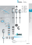
10.2.1 Connection digital outputs (e.g. Machine functions)
Operating Instructions CPS300
10.3 Technical data inputs and outputs
Digital inputs 24V:
32 digital inputs 24V
electrically decoupled
Input resistance Ri = 10-20kohm
Voltage threshold high level > = 12 volt
Voltage threshold low level < = 3 volt
Incremental shaft encoder connexions:
One incremental shaft encoder connexion per axle
Input signal levels according to RS422
- Zero pulse (UA0)
- Inverted zero pulse (/UA0)
- Channel A (UA1)
- Channel A inverted (/UA1)
- Channel B (UA2)
- Channel B inverted (/UA2)
5V supply voltage output max. 300mA
Analog inputs (option):
3 analog inputs
Input voltage 0..10V
Resolution 10 bits
Internal resistance Ri = 10 kohm
Digital outputs 24V:
16 electrically decoupled transistor outputs
+24V max. 1 A per output
8A maxi overall
Short circuit-proof
Supply 24 V d.c. voltage, external source
Release outputs:
One potential-free change-over contact per axle for "controller release" of
servo
amplifier.
Contact rating at 24 V approx. 1 A
Analog outputs:
1 analog output per axle
-10V...+10V for servo amplifier
Resolution 12 bits
Internal resistance Ri = 1,2kohm
Maximum output current 5 mA
35
36
Operating Instructions CPS300
11. Technical data controller
Number of axles
1-3 axles
Input
Membrane keyboard with tactile
acknowledgement
Display
Illuminated LCD display 4*40 characters
Number of programs
99 programs
Number of records
2047 records (protected against power failure)
Gear adaptation
0.001 - 9999.999 increments / mm
Control cycle time
2 ms
Controller release
1-3 potential-free contact (change over contacts)
Position Acquisition
Incremental to 250kHz (internal 4x interpolation)
SSI-Interface (option) 8 to 32-bit data word length
Transsonar interface (option)
Encode supply
5 V, max. 300mA per axle
Inputs and outputs
32 digital inputs 24V
16 digital outputs 24V
3 analog inputs (option)
3 analog set value outputs -10V...+10V
Supply voltage
220 VAC, approx. 0,2A; 50 Hz
24 VDC for signal outputs
Operating temperature
0o to 45oC
Storage temperature
-20o to 70oC
Humidity
max. 90 %, non-condensing
Connector plug
Clamping plug
Dimensions h x w x d
170 x 320 x 95 mm
Operating Instructions CPS300
37
12. Options
Card reader for memory card (external memory)
A card reader may be connected to the serial interface for the storage or transfer of
programs and parameters from or to a CPS300.
13. Precautions
!
The control checks control-internal and operating conditions at
the system side. But uncontrolled movements caused by
defective components cannot be avoided in any case.
Therefore, personal danger has to be avoided at the system side
by interrupting the operating voltage via the "EMERGENCY STOP" chain.
38
Operating Instructions CPS300
Operating Instructions CPS300
39
40
Operating Instructions CPS300
Connector no.
Pin no.
X1
1
no function
(RS 232)
2
RxD (Receive Data)
3
TxD (Transmitt Data)
4
no function
5
GND RS232
6
no function
7
no fucntion
8
no function
9
+5V
1
Analog input 1+
2
Analog input 1-
3
Analog input 2+
4
Analog input 2-
5
Analog input 3+
6
Analog input 3-
1
Release output 1
2
Release output 1 normally open
3
Release output 1 normally closed
4
Release output 2
4
Release output 2 normally open
6
Release output 2 normally closed
7
Release output 3
8
Release output 3 normally open
9
Release output 3 normally closed
10
no function
1
Analog output axle 1+
2
Analog output axle 1-
3
Analog output axle 2+
4
Analog output axle 2-
5
Analog output axle 3+
6
Analog output axle 3-
7
Analog output auxiliary axle +
8
Analog output auxiliary axle Pin assignment CPS300
Connectors X1,X2,X3,X4
X2
X3
X4
esitron-electronic GmbH
88045 Friedrichshafen
Function
Operating Instructions CPS300
41
Connector no.
Pin no.
X5
1
Incremental encoder channel B
(Axle 1)
2
Incremental encoder channel B inv.
3
Incremental encoder supply 0V
4
Incremental encoder channel A
5
Incremental encoder channel A inv.
6
Incremental encoder supply 0V
7
Incremental encoder zero pulse (Ref.)
8
Incremental encoder zero pulse inv.
9
Incremental encoder supply +5V
X6
1
Incremental encoder channel B
(Axle 2)
2
Incremental encoder channel B inv.
3
Incremental encoder supply 0V
4
Incremental encoder channel A
5
Incremental encoder channel A inv.
6
Incremental encoder supply 0V
7
Incremental encoder zero pulse (Ref.)
8
Incremental encoder zero pulse inv.
9
Incremental encoder supply +5V
X7
1
Incremental encoder channel B
(Axle 3)
2
Incremental encoder channel B inv.
3
Incremental encoder supply 0V
4
Incremental encoder channel A
5
Incremental encoder channel A inv.
6
Incremental encoder supply 0V
7
Incremental encoder zero pulse (Ref.)
8
Incremental encoder zero pulse inv.
9
Incremental encoder supply +5V
1
+24V for digital outputs
2
Ground for 24V supply
1
PE / protective conductor
2
N / neutral conductor
X16
X17
3
esitron-electronic GmbH
88045 Friedrichshafen
Function
L1 / phase
Pin assignment CPS300
Con. X5,X6,X7,X16,X17
42
Operating Instructions CPS300
Connector no.
Pin no.
X8
1
Limit switch axle 1 +
2
Reference switch axle 1
3
Limit switch axle 1 -
4
Limit switch axle 2 +
5
Reference switch axle 2
6
Limit switch axle 2 -
7
Limit switch axle 3 +
8
Reference switch axle 3
9
Ground digital inputs
1
Limit switch axle 3 -
2
Release
3
Automatic / manual
4
Stop
5
Motor monitoring
6
not assigned
7
not assigned
8
Start
9
Ground digital inputs
1
Input 1
2
Input 2
3
Input 3
4
Input 4
5
Input 5
6
Input 6
7
Input 7
8
Input 8
9
Ground digital inputs
1
Input 9
2
Input 10
3
Input 11
4
Input 12
5
Input 13
6
Input 14
7
Input 15
8
Input 16
X9
X10
X11
9
esitron-electronic GmbH
88045 Friedrichshafen
Function
Ground digital inputs
Pin assignment CPS300
Con. X8,X9,X10,X11
Operating Instructions CPS300
43
Connector no.
Pin no.
X12
1
Machine function 1 M1
2
Ground
3
Machine function 2 M2
4
Ground
5
Machine function 3 M3
6
Ground
7
Machine function 4 M4
8
Ground
1
Machine function 5 M5
2
Ground
3
Machine function 6 M6
4
Ground
5
Machine function 7 M7
6
Ground
7
Machine function 8 M8
8
Ground
1
Machine function 9 M9
2
Ground
3
Teach-In
4
Ground
5
In Position / Positioning
6
Ground
7
Quantity end
8
Ground
1
Record end
2
Ground
3
Program end / Running program
4
Ground
5
Automatic ready
6
Ground
7
Ready (error message)
X13
X14
X15
8
esitron-electronic GmbH
88045 Friedrichshafen
Function
Ground
Pin assignment CPS300
Con. X12,X13,X14,X15