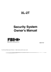
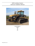
1
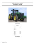
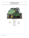
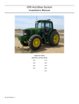
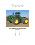
GPS AutoSteer System
Installation Manual
John Deere MFWD AutoTrac Ready
Supported Models
8225R
8245R
8270R
8295R
8320R
8345R
PN: 602-0254-01-A
LEGAL DISCLAIMER
Note: Read and follow ALL instructions in this manual carefully before installing or operating the AutoSteer system.
Note: Take careful note of the safety information in the Safety Information section and throughout this manual.
The manufacturer disclaims any liability for damage or injury that results from the failure to follow the instructions and
warnings set forth herein.
Please take special note of the following warnings:
1.
There is NO obstacle avoidance system included in the manufacturer’s product. Therefore, users must always have an
operator on the equipment when the AutoSteer system is in use to look for any obstacles including people, animals, trees,
ditches, buildings, etc.
2.
During installation of the AutoSteer system and during the Calibration and Tuning processes, the vehicle's wheels turn
from side to side and the vehicle moves. Be sure that all people and obstacles are clear of the vehicle before installation,
calibration and tuning, or use of the AutoSteer system.
3.
Use of the AutoSteer system is NOT permitted while the vehicle is on public roads or in public areas. Ensure that the
system is OFF before driving on roads or in public areas.
Hardware Installation Guide
ii
Special Requirements
Tools
This list consists of the tools required to complete the installation. The installer is assumed to have a complete set of common
installation tools.
1/8” Allen wrench
3/8” open wrench
13mm open wrench
5/32” Allen wrench
1/2” open wrench
10mm socket and ratchet
4mm Allen wrench
9/16” open wrench X2
13mm socket, extension, and ratchet
#2 Phillips screwdriver, standard
15/16” open wrench
14mm socket, extension, and ratchet
#2 Phillips screwdriver, short
Wire cutter small
17mm socket and ratchet
9/16” socket and ratchet
Ohm meter
T20 Torx socket and ratchet
15/16” socket and ratchet
Metal hack saw
Ladder, 10 ft (3 m)
Oil catch pan
Cleaning rags
Tape measure, 12 ft (3.7m) minimum
Cleaning brush
Cable puller pole
Hardware Installation Guide
iii
Safety Information
Warning Alerts
The AutoSteer system installer and manufacturer disclaim any responsibility for damage or physical harm caused by failure to
adhere to the following safety requirements:
•
•
As the operator of the vehicle, you are responsible for its safe operation.
The steering system is not designed to replace the vehicle’s operator.
Note: Verify that all screws, bolts, nuts, hose connections, and cable connections are tight after the final installation of the
AutoSteer system on the vehicle.
To avoid electrical shock hazards, remove the Roof Module
from the vehicle before driving under low structures or low
electrical power lines.
Ensure that you are in a stable position on the vehicle
platform when installing or removing the Roof Rail and Roof
Module so you do not fall.
To prevent accidental death or injury from being run over by
the vehicle, never leave the vehicle’s operator chair with the
AutoSteer system engaged.
iv
AutoSteer System
To understand the potential hazards associated with the
operation of AutoSteer equipment read the provided
documentation before installing the AutoSteer system on a
vehicle.
To prevent the accidental engagement of the AutoSteer and
loss of vehicle control while driving on roads, shut down the
AutoSteer system (exit the program). Never drive on roads
or in public areas with the AutoSteer system turned on.
Hardware Installation Guide
v
Caution Alerts
The AutoSteer system installer and manufacturer disclaim any responsibility for damage or physical harm caused by failure to
adhere to the following safety requirements:
The Roof Module must be removed when transporting or
driving the vehicle at speeds above 30 mph (48 km/h). The
Roof Module can possibly detach due to wind loads at
higher speeds.
The AutoSteer system does not detect obstacles in the
vehicle’s path. The operator must observe the path being
driven in order to avoid obstacles.
When engaged, the AutoSteer system controls only the
steering of the vehicle. The operator must control the speed
of the vehicle.
The AutoSteer system must be powered OFF when
installing or removing the Roof Module.
vi
AutoSteer System
The Roof Module must always be firmly secured to the Roof
Rail using the supplied hardware whenever the vehicle is in
operation to prevent the Roof Module from releasing from its
bracket and falling.
Vehicle Requirements
The vehicle must be AutoTrac1 Ready with the factory installed Steering Valve, Kingpin Sensor, and Steering Wheel Encoders
installed.
The vehicle steering system must be in good working order before installing the AutoSteer system. Check for loose or worn
parts. Drive the vehicle before installing the AutoSteer system and confirm that it steers straight and the wheels can be turned
from lock to lock.
The vehicle electrical system and battery must be in good working order.
The vehicle should be fully cleaned before installing the AutoSteer system. A clean vehicle will improve the overall
installation and cable routing.
1
AutoTrac is a trademark of Deere & Company
Hardware Installation Guide
vii
Important Information
This installation manual contains valuable information for servicing the AutoSteer system. After the installation is complete,
store this manual in a safe place for future reference.
Note: Verify that all screws, bolts, nuts, hose connections, and cable connections are tight after the final installation of the
AutoSteer system on the vehicle.
This installation requires that the pressure relief valve on the Steering Valve be adjusted after the system has been installed but
prior to calibration and tuning. After a preliminary hydraulic leak test, follow the procedure for setting the pressure relief
valve.
Technical Support
Refer to your Display user manual for technical support information.
Contact Information
Refer to your Display user manual for contact information.
Copyright © 2009 All Rights Reserved.
viii
AutoSteer System
Table of Contents
Chapter 1
Installation Overview.......................................................................................... 1
Vehicle Inspection.........................................................................................................................1
Kit Overview.................................................................................................................................1
Kit Components .....................................................................................................................2
Assemblies .............................................................................................................................2
John Deere AutoTrac Ready Common Kit Components ............................................ 3
Bracket Kit Components .............................................................................................. 4
AutoTrac Termination Kit Components ...................................................................... 5
Installation Procedure Outline.......................................................................................................6
Cable Diagram ..............................................................................................................................7
Chapter 2
Wheel Angle Sensor Installation (Optional) ............................................................ 9
Wheel Angle Sensor Overview.....................................................................................................9
Wheel Angle Sensor Installation Procedure................................................................................10
Mount Brackets on ILS Front Axle......................................................................................10
Cut the Wheel Angle Sensor Rods.......................................................................................13
Assemble the Linkage Rod Hardware..................................................................................14
Attach Wheel Angle Sensor Rods to Brackets and Adjust ..................................................17
Chapter 3
SA Module Installation...................................................................................... 23
SA Module Mounting Orientation ..............................................................................................23
Mount the SA Module.................................................................................................................24
Chapter 4
Roof Module Installation ................................................................................... 27
Safety Notes ................................................................................................................................27
Roof Rail Installation ..................................................................................................................28
Chapter 5
Display Installation ........................................................................................... 33
Introduction.................................................................................................................................33
Installation Procedure .................................................................................................................33
Chapter 6
Connecting System Cables................................................................................ 35
SA Module Harness ....................................................................................................................36
SA Module Connection........................................................................................................36
AutoTrac Valve Connection ................................................................................................37
Wheel Angle Sensor Connections (Optional) ......................................................................40
Factory Installed Wheel Angle Sensor - Non ILS Only .............................................. 40
Optional AutoSteer Wheel Angle Sensor – ILS Axle Only......................................... 46
AutoTrac Wheel Angle Sensor / Flow Sensor Termination.................................................46
AutoTrac Wheel Angle Sensor Termination - Not using Factory Installed Wheel
Angle Sensor on Standard Front Axle Installations Only............................................ 47
Flow Sensor Termination – All ILS Front Axle Installations Only ............................. 50
AutoTrac Steering Wheel Encoder Connection ...................................................................57
Main Cable Harness ....................................................................................................................65
Roof Module ........................................................................................................................65
SA Module Harness .............................................................................................................68
Main Cable Harness Connections Inside Cab......................................................................70
Power Supply Connection...........................................................................................................71
Cab Power Connection ........................................................................................................71
Battery Power Connection ...................................................................................................72
Chapter 7
Post-Installation Procedures and Information ....................................................... 73
Create New Vehicle ....................................................................................................................73
Hardware Installation Guide
ix
Calibration and Tuning Guidelines .............................................................................................74
Chapter 8
x
Final Hardware Installation Checklist .................................................................. 75
Final Hardware Installation Checklist..................................................................................76
AutoSteer Performance Checklist........................................................................................76
AutoSteer System
1
Installation Overview
The Installation Overview chapter information is provided in the following sections:
•
•
•
•
Vehicle Inspection
Kit Overview
•
•
Kit Components
Assemblies
Installation Procedure Outline
Cable Diagram
This installation guide describes the installation of the AutoSteer system on the John Deere MFWD vehicles with an AutoSteer
Steering Valve. The AutoSteer installation kit PN: 188-0048-01 is used on the following vehicles:
•
John Deere 8XXXR AutoTrac Ready Wheeled (8225R, 8245R, 8270R, 8295R, 8320R, and 8345R)
The vehicle specific sub-assemblies for the vehicle series are listed in Table 1-1.
Note: If you are installing an electric steering wheel actuator such as OnTrac II, skip the Steering Valve, SA Module, and SA
Module Harness installation information in this book and refer to your electric steering product manual for further instructions.
Vehicle Inspection
Before installing the AutoSteer system, confirm the vehicle’s steering system is in good working order. Drive the vehicle and
verify the vehicle’s correct working order. Also, ensure the following system operations and components:
•
•
•
•
•
Check to see if you can turn the steered wheels from lock to lock.
Ensure the vehicle steers straight.
Check for loose or worn steering components.
Ensure the hydraulic fluid level is correct.
Service the vehicle if the steering is not in good working order.
Kit Overview
This Kit Overview section is divided into sub-sections for each of the assemblies and their components are described in the
following sections.
Hardware Installation Guide
1
Kit Overview
Kit Components
This assembly is shown in Figure 1-1 and its components are defined in Table 1-1.
Figure 1-1
Installation Kit Components (PN: 188-0048-01)
Table 1-1
Installation Kit Component Descriptions (PN: 188-0048-01)
Item
Component
Part Number
1.
John Deere AutoTrac Ready
Common Kit Components
153-0002-01
2.
Bracket Kit
152-0062-01
Assemblies
This vehicle installation kit contains the following components:
•
•
•
2
John Deere AutoTrac Ready Common Kit Components
Bracket Kit Components
AutoTrac Terminator Kit Components
AutoSteer System
Kit Overview
John Deere AutoTrac Ready Common Kit Components
Figure 1-2
John Deere AutoTrac Ready Common Kit Components (PN: 153-0002-01)
Table 1-2
Steering Valve Kit Components (PN: 153-0002-01)
Item
Component
Part Number
1.
SA Module Assembly
200-0206-01
2.
SA Module Harness – AutoTrac
Ready
201-0240-02
3.
Common Installation Kit
200-0497-02
4.
SA Module Bracket
200-0190-01
5.
Mounting Hardware
200-0076-01
6.
Display Mounting Base Assembly
200-0508-01
7.
Warning Labels
603-0074-01
Hardware Installation Guide
3
Kit Overview
Bracket Kit Components
Figure 1-3
Bracket Components (PN: 152-0062-01)
Table 1-3
Bracket Kit Components (PN: 152-0062-01)
Item
Component
Part Number
1.
Display Bracket Assembly
200-0469-02
2.
Install Manual
602-0254-01
3.
Termination Kit JD AT #5
200-0544-01
4.
Roof Rail Mounting Kit
200-0543-01
4
AutoSteer System
Kit Overview
AutoTrac Termination Kit Components
Figure 1-4
AutoTrac Termination Kit Components (PN: 200-0544-01)
Table 1-4
AutoTrac Termination Kit Components (PN: 200-0544-01)
Item
Component
Part Number
When to Use
1.
Steering Encoder Terminator (High)
201-0241-01
All
2.
Steering Encoder Terminator (Low)
201-0242-01
All
3.
M5x24 Screws
515-0013-01
ILS Installs
4.
Spacers
500-0214-01
ILS Installs
5.
Cables Ties
510-0015-01
All
6.
Vehicle WAS Terminator
201-0473-01
Standard Front Axle Installs
7.
AutoSteer Wheel Angle Sensor
Cable Adapter
201-0472-01
Standard Front Axle Installs
8.
WAS Dummy Connector
201-0486-01
Standard Front Axle Installs when not Using Factory Installed
Wheel Angle Senor
Hardware Installation Guide
5
Installation Procedure Outline
Installation Procedure Outline
1.
Verify shipped components.
Note: Step 2, Step 3, and Step 7 are skipped if installing an electric steering actuator.
2.
Install the Wheel Angle Sensor (Optional).
3.
Install the SA Module.
4.
Install the Roof Rail on the cab roof.
5.
Install the Roof Module on the Roof Rail.
6.
Install the Display Mounting bracket in the cab.
7.
Install the SA Module Harness.
8.
Install the Main Cable Harness.
9.
Install the Display using a RAM Mount Arm.
10. Connect the Main Cable Harness to the Display connections (Display Comm, Display Eth, and Vehicle Power)
Note: Instructions for connecting the vehicle kit cables to the Display can be found in the Display user manual.
11. Verify that all connectors are properly coupled and secured.
12. Start the vehicle and check for oil leaks.
13. Power ON the AutoSteer system.
14. Adjust the pressure relief valve on the Steering Valve
15. Calibrate the vehicle.
16. Tune the vehicle.
17. Verify the system has been installed properly and operates satisfactorily.
6
AutoSteer System
Cable Diagram
Cable Diagram
Hardware Installation Guide
7
2
Wheel Angle Sensor Installation
(Optional)
The Wheel Angle Sensor Installation chapter information is provided in the following section:
•
•
Wheel Angle Sensor Overview
Wheel Angle Sensor Installation Procedure
• Mount Brackets on ILS Front Axle
• Cut the Wheel Angle Sensor Rods to Length
• Assemble the Linkage Rod Hardware
• Attach Wheel Angle Sensor Rods to Brackets and Adjust
Note: The Wheel Angle Sensor is optional equipment and is not provided with the installation kit. The Wheel Angle
Sensor installation instructions are provided for special installations, when required.
Wheel Angle Sensor Overview
This vehicle comes standard with a factory installed Kingpin Wheel Angle Sensor for the standard front axles or a Flow Meter
for the Independent Link Suspension (ILS) front axle. This installation kit assumes that either the factory installed Wheel
Angle Sensor is going to be used on standard front axles or a Wheel Angle Sensor is installed on ILS front end models. For the
ILS installations additional parts are required. The additional parts required are provided in Table 2-1 for reference. Contact
your AutoSteer dealer to get the current part numbers and to order them if this accessory is desired.
Table 2-1
John Deere 8XXXR Wheel Angle Sensor Kit Component Part Numbers
Item
Component
Part Number
1.
Wheel Angle Sensor Assembly Kit
200-0468-01
2.
John Deere Wheel Angle Sensor Brackets
8XXXR ILS Kit
200-0061-03
Hardware Installation Guide
9
Wheel Angle Sensor Installation Procedure
Wheel Angle Sensor Installation Procedure
Mount Brackets on ILS Front Axle
1.
Identify the Wheel Angle Sensor mounting location on left axle shown in Figure 2-1.
Figure 2-1
Wheel Angle Sensor Mounting Position (Picture from the Front)
ILS Wheel Angle
Mounting Position
2.
Remove the bolt on the steering axle identified in Figure 2-2.
Note: Verify that the correct bolt is removed. Connecting to the wrong bolt will cause incorrect Wheel Angle Sensor
geometry and thus cause the sensor or the axle to become damaged.
Figure 2-2
Remove Axle Bolt
Remove Bolt
10
AutoSteer System
Wheel Angle Sensor Installation Procedure
3.
Attach the Wheel Angle Sensor bracket to the vehicle with the bolt that was just removed so that the flat part of the
bracket is perpendicular to the ground as shown in Figure 2-3. Torque the bolt to 229 Ft-Lbs (310 Nm).
Figure 2-3
Option 1 Wheel Angle Sensor Bracket Installed
Bracket
4.
Attach the Wheel Angle Sensor to the Wheel Angel Sensor bracket with the two 3/8” x 5/8” bolts and flat washers as
shown in Figure 2-4. Tighten the bolts with a 9/16” socket and ratchet.
Figure 2-4
Attach Wheel Angle Sensor
Wheel Angle Sensor
Hardware Installation Guide
11
Wheel Angle Sensor Installation Procedure
5.
Remove the two bolts on the tie rod shown in Figure 2-5.
Figure 2-5
Remove Tie Rod Bolts
Remove Bolts
6.
Attach the Wheel Angle Sensor linkage rod bracket to the back of the tie rod as shown in Figure 2-6 with the bolts just
removed. Torque the bolts to 90 Ft Lbs (125 Nm).
Figure 2-6
12
Wheel Angle Sensor Linkage Rod Bracket Mounted
AutoSteer System
Wheel Angle Sensor Installation Procedure
Cut the Wheel Angle Sensor Rods
The Wheel Angle Sensor rods are shipped longer than they need to be. These rods must be cut to the proper length to allow the
linkage rods to provide the Wheel Angle Sensor the maximum number of counts as the steering wheel is turned from full right
to full left. Due to the variability of the possible mounting positions and axle options, it is the responsibility of the installer to
verify the lengths provided in Table 2-2 are correct for each individual installation prior to cutting the rods.
Table 2-3 provides the typical rod lengths that work for most installations. Before cutting the linkage rods to these
measurements, verify that the Wheel Angle Sensor brackets have been attached to the vehicle as shown in this manual and that
they are attached the correct distance from any reference points shown. If the axle does not allow the Wheel Angle Sensor
brackets to be installed as shown, do not cut the rods until it is determined what the proper lengths are for your installation.
Even if the brackets can be attached as shown, these measurements may need to be slightly different to take into account minor
installation differences. These measurements are provided as a reference only. The installer is responsible for verifying that
the provided measurements will work prior to cutting the rods.
Refer to Figure 2-7 to determine where the measurement points on the rods are taken to get the values provided in Table 2-2.
Table 2-2
Linkage Rod Cut Lengths
Item
ILS Axle
Rod A
5 inches (127 mm)
Rod B
9-1/2 inches (241 mm)
Figure 2-7
Linkage Rod Cut Length Measurement Points
Hardware Installation Guide
13
Wheel Angle Sensor Installation Procedure
1.
Use a metal hack saw and vice as shown in Figure 2-8 to cut the Wheel Angle Sensor linkage rods to the proper lengths.
Note: Protect the threads from damages while cutting the rods. It is advisable to attach a nut on the side of the linkage rod that
is going to be kept in order to clean the threads after the cut has been made.
Figure 2-8
Linkage Rod Cutting
Assemble the Linkage Rod Hardware
1.
Attach a locking nut to the end of Rod A.
2.
Connect the eye connector to the end of the Wheel Angle Sensor rod. See Figure 2-9.
Figure 2-9
Rod A Assembled
Locking Nut
Eye Connector
14
AutoSteer System
Wheel Angle Sensor Installation Procedure
3.
Attach the locking nuts to each end of the linkage Rod B.
4.
Attach the ball joints to both ends of the linkage arm as shown in Figure 2-10.
Note: The bolts for the ball joints should be facing the same direction as shown in Figure 2-10 for this installation.
Figure 2-10 Linkage Rod Assembled for ILS Axle
Locking Nuts
Ball Joints
Hardware Installation Guide
15
Wheel Angle Sensor Installation Procedure
5.
For most installations, use Table 2-3 to adjust the lengths of the rod assemblies to the values shown. Figure 2-12 shows
where the measurement points for each rod are taken.
Note: Due to the variation of axle types and installation points, these measurements are provided as a reference only. Before
connecting the steering rods and turning the steering axle verify that these lengths will work and the sensor will not be
damaged.
Table 2-3
Assembled Linkage Rod Length
Item
ILS Axles
Rod A
5-7/8 inches (149 mm)
Rod B
11-1/2 inches (292 mm)
Figure 2-11 Assembled Linkage Rod Measurement Points
16
AutoSteer System
Wheel Angle Sensor Installation Procedure
Attach Wheel Angle Sensor Rods to Brackets and Adjust
1.
Attach the Wheel Angle Sensor rod to the Wheel Angle Sensor. The rod will point backwards.
Note: The flat washer goes on the bolt head side and NOT the nut side when attaching the arm. See Figure 2-12.
Figure 2-12 Washer on Shaft Bolt
Nut
Flat Washer
Allen Bolt Head
Note: The bolts should stick out of the bottom of the Wheel Angle Sensor and are used to prevent the sensor from being
accidentally over extended by hand. Ensure these bolts are installed correctly. These bolts will not stop the hydraulics from
over extending the sensor. Verify the fit prior to manually or automatically moving the Wheel Angle Sensor fully connected.
2.
Tighten the bolt on the Wheel Angle Sensor shaft with a 1/8” Allen wrench and a 3/8” open end wrench.
Hardware Installation Guide
17
Wheel Angle Sensor Installation Procedure
3.
Attach the linkage rod to the linkage bracket. The bolt attaches from the top of the linkage bracket and the nut and lock
washer go on the bottom.
4.
Tighten the ball joint to the bracket with a 1/2" and 9/16” wrench. Figure 2-13 shows both rods connected to the brackets
and to each other. Disconnect the rods from each other prior to turning the moving the steering axle.
Figure 2-13 Linkage Connections
Note: Never attach the linkage rods to Wheel Angle Sensor rod and turn the steering wheels manual or automatically until the
fit has been verified. The linkage rods must remain apart while the steering wheels are turned to the maximum right and left
positions and then temporarily attached at these positions. Failure to do this may cause the Wheel Angle Sensor or vehicle to
become damaged.
Always shut down the vehicle when working around the
steering axle and checking and adjusting the Wheel Angle
Sensor rod lengths. The steering axle could move suddenly
and cause severe injury or death.
Note: Before adjusting the Wheel Angle Sensor linkage rods, verify the steering wheels physical stops on the vehicle are
adjusted to the maximum setting the vehicle operator is going to use. If these physical stops are changed after the Wheel Angle
Sensor has been adjusted, the Wheel Angle Sensor could be damaged when the wheels are turned farther that what it was
originally adjusted to work at.
5.
With the linkage rods disconnected, start the vehicle and manually turn the steering wheel so that the vehicle will travel
straight ahead when moving.
6.
Temporarily attach the linkage rods together.
7.
Rotate the Wheel Angle Sensor potentiometer on top of the mounting block so that the plastic wire connector is parallel to
the Wheel Angle Sensor rod. See Figure 2-14.
18
AutoSteer System
Wheel Angle Sensor Installation Procedure
Figure 2-14 Adjust Potentiometer Angle to Match Straight Ahead Wheel Position
Adjust the orientation of potentiometer
sensor so that the wire connector is
parallel to wheel angle sensor arm
when wheels are straight ahead
Tire Direction in Straight Ahead Position
8.
After the potentiometer has been adjusted, tighten the potentiometer bolts with a 3/8” wrench and 5/32” Allen wrench
9.
Disconnect the linkage rods and turn the steering wheel manually to the full left position.
Note: The vehicle may need to be driven a short distance in order to get the steering system to move to the full left position
10. Reattach the linkage assembly and verify that the sensor will not be damaged. Adjust the rod lengths as necessary. See
Figure 2-15.
Figure 2-15 Confirm Maximum Steer Left Position
11. Disconnect the linkage rods and turn the steering wheel to the full right position.
Note: The vehicle may need to be driven a short distance in order to get the steering system to move to the full right position
Hardware Installation Guide
19
Wheel Angle Sensor Installation Procedure
12. Reattach the linkage assembly and verify that the sensor will not be damaged. Adjust the rod lengths as necessary. See
Figure 2-16.
Figure 2-16 Confirm Maximum Steer Right Position
13. Repeat Steps 5 through 12 until the rod lengths have been adjusted and the potentiometer is centered to get the maximum
sensor movement. The maximum movement is reached when the Wheel Angle Sensor rod will sweep from approximately
3/16 inch (5mm) from both bolt heads holding the potentiometer on to the mounting block when the wheels are turned to
the maximum right and left positions. See Figure 2-17.
Figure 2-17 Maximum Sensor Movement
Potentiometer Screw Stops
Wheel Angle Sensor as
Seen from the Bottom
Full
Left
Movement Range
Full
Right
Note: An Ohm meter can also be used to determine if there is enough sensor movement. Connect the Ohm meter to pins A
and B of the Wheel Angle Sensor. Measure the Ohm reading at the maximum left and right position. After subtracting the
smaller number from the larger number, there should be at least a 3.75 Kilo-Ohms change. The reading should also never go
below 1.5 or higher than 6.6 Kilo-Ohms as this is reaching the limits of the potentiometer and could damage the sensor.
20
AutoSteer System
Wheel Angle Sensor Installation Procedure
14. Once all the adjustments are complete, tighten all lock nuts and bolts on the linkage and Wheel Angle Sensor rod. A 1/2”
and two 9/16” wrenches are required to tighten all the connections.
15. Figure 2-18 shows the Wheel Angle Sensor fully installed on an ILS axle.
Figure 2-18 ILS Axle Final Install
Hardware Installation Guide
21
3
SA Module Installation
The SA Module Installation chapter contains information in the following section:
•
•
SA Module Mounting Orientation
Mount the SA Module
SA Module Mounting Orientation
The SA Module can only be mounted in certain orientations. Figure 3-1 shows the allowable mounting positions and Figure
3-2 shows the incorrect mounting positions.
Figure 3-1
Correct SA Module Mounting Orientations
Figure 3-2
Incorrect SA Module Mounting Orientations
Hardware Installation Guide
23
Mount the SA Module
Due to the variety of options available on vehicles and the possible configuration differences, it may be necessary to install the
SA Module in location other than the example shown here. If an alternative location is required, choose a location where the SA
Module can be protected from damage from moving parts or crop debris and excessive moisture from weather and cleaning
equipment.
Mount the SA Module
1.
Locate the rear panel on the back of the cab shown in Figure 3-3. Remove the four bolts holding it on with a 14mm
socket, extension, and ratchet
Figure 3-3
Back Panel
Cover Bolts
2.
Locate the SA Module mounting position on the bottom of the right, rear cab support under the cab shown in Figure 3-4.
Figure 3-4
Locate SA Module Mounting Position
SA Module Bracket
Mounting Position
24
AutoSteer System
Mount the SA Module
3.
Locate the existing hole at the bottom of the cab support shown in Figure 3-5.
Figure 3-5
SA Module Bracket Mounting Hole
SA Module
Bracket
Mounting Hole
4.
Start two of the SA Module mounting screws on the “L” bracket side of the SA Module mounting bracket.
5.
Attach the SA Module mounting bracket to the frame of the vehicle using a 3/8” x 1 1/4” hex bolt, flat washer, and nut
provided with the installation kit as shown in Figure 3-6. Tighten the bolt with a 9/16”wrench and 9/16” socket and
ratchet.
Figure 3-6
SA Module Bracket Installed
Bolt Securing
SA Module
Bracket
SA Module
Bracket
Hardware Installation Guide
25
Mount the SA Module
6.
Attach the SA Module to the SA Module bracket and secure with the other two Phillips screws. Tighten the SA Module to
the bracket with a short #2 Phillips screwdriver. Figure 3-7 shows the SA Module installed.
Note: The upper, right corner (as seen from the rear) of the SA Module will be a tight fit. However, it will fit between the SA
Module bracket and the bracket on the back of the machine if the bracket at the back of the machine is forced backwards
slightly as the SA Module is slid into place.
Figure 3-7
SA Module Mounted
SA Module
26
AutoSteer System
4
Roof Module Installation
The Roof Module Installation chapter contains information in the following sections:
•
•
Safety Notes
Roof Rail Installation
Safety Notes
•
•
•
•
•
The AutoSteer system must be powered OFF when installing or removing the Roof Module.
The Roof Module must always be firmly secured to the roof rail using the hardware provided whenever the vehicle is in
operation to prevent the Roof Module from releasing from its bracket and falling.
The Roof Module must be removed when transporting the vehicle at speeds above 30 mph (48 km/h).
Ensure you are in a stable position on the vehicle platform when removing the Roof Module so that you do not fall or drop
the Roof Module.
Use a ladder to install the AutoSteer Roof Rail
Ensure that you are in a stable position on the vehicle
platform when installing or removing the Roof Rail and Roof
Module so you do not fall.
Hardware Installation Guide
27
Roof Rail Installation
Roof Rail Installation
1.
Locate the two mounting bolts on top of the cab shown in Figure 4-1.
Figure 4-1
Mounting Bolt Location
Mounting Bolts
2.
Remove the two bolts and flat washers with a 15/16” socket and ratchet.
3.
Place a M16 x 30mm bolt and flat washer in the hole closest to the bend and another one in the hole farthest from the bend
of the Roof Rail Mounting Bracket as shown in Figure 4-2
Figure 4-2
28
Insert Mounting Bolts
AutoSteer System
Roof Rail Installation
4.
Attach the Roof Rail Mounting Bracket to the roof using the bolt and washer that was just removed. The threads of the
bolts inserted in Step 3 should point upward as shown in Figure 4-3. Hand tighten the bolts so the brackets are snug, but
do not tighten completely yet.
Figure 4-3
Attach the Roof Rail Mounting Bracket (Left Side Shown)
Roof Rail
Mounting Bracket
5.
Repeat the process for the Roof Rail Mounting Bracket on the other side of the cab.
6.
Place the Roof Rail on top of the Roof Rail Mounting Brackets and center it over the cab. Ensure that the Roof Rail is
perpendicular to the front of the vehicle before tightening the bolts.
7.
Secure the Roof Rail mounting bracket with four M16 flat washers and nuts to the four bolts pointing upward. Tighten the
bolts with a 15/16” wrench and 15/16” socket and ratchet. See Figure 4-4.
Figure 4-4
Attach Quick Attach Rail
Roof Rail
Mounting Bolt
8.
After the Roof Rail bolts have been tightened, finish tightening the two original roof bolts that hold the Roof Rail
Mounting Brackets to the roof with a 15/16” wrench.
Hardware Installation Guide
29
Roof Rail Installation
9.
Attach the three antennas to the proper antennas connections on the Roof Module. See Figure 4-5.
Note: Hand tighten the connections. Do not over tighten.
Figure 4-5
Attach the Antennas
RTK Radio
Modem Antenna
Cell Modem
Antenna
WiFi Antenna
10. Place the Roof Module on the Roof Rail
11. Remove the locking pin from the Roof Rail. See Figure 4-6.
Figure 4-6
Removing the Locking Pin
Locking Pin
`
12. Adjust the Roof Module position on the Roof Rail.
30
AutoSteer System
Roof Rail Installation
13. Re-insert the locking pin to lock the Roof Module onto the vehicle. See Figure 4-7.
Figure 4-7
Locking Pin Inserted
Roof Module
Locked in
14. The Roof Module is now installed. See Figure 4-8.
Figure 4-8
Roof Module Installed
Hardware Installation Guide
31
5
Display Installation
The Display Installation chapter contains information in the following sections:
•
•
Introduction
Installation Procedure
Introduction
This manual provides the instructions for installing the RAM mount ball in the cab so that the Display can be attached later.
Refer to your Display’s user manual for instructions on installing the Display
If the location shown for mounting the Display is being used by another piece of equipment, other mounting locations can be
used. However, for best performance and ease of use, use the location shown in the installation manual.
Installation Procedure
1.
Locate the accessory mounting bracket holes on the front right corner cab post. If necessary, remove existing John Deere
bracket. See Figure 5-1.
Figure 5-1
Identify the Bracket Mounting Holes
Mounting Holes for User Display
Bracket
Hardware Installation Guide
33
Installation Procedure
2.
Attach the Display Bracket to the mounting holes with the two M10 x 20mm bolts and washers included with the Display
Bracket installation kit. The bracket should attach so it angles away from the right window as shown in Figure 5-2.
Tighten the bracket with a 17mm socket and ratchet.
Figure 5-2
Monitor Bracket Installed
Bracket Bolts
3.
Attach the RAM mount ball to mounting bracket using the four 10-32x3/4 Phillips screws and lock nuts provided.
Tighten using a 3/8” wrench and #2 Philips screwdriver. See Figure 5-3
Figure 5-3
Mounted Display Bracket
RAM Mount Base
Note: Refer to the Display user manual for the remaining Display specific installation instructions.
34
AutoSteer System
6
Connecting System Cables
The Connecting System Cables chapter provides information in the following sections:
•
SA Module Harness
• SA Module Connection
• AutoTrac Valve Connection
• Wheel Angle Sensor Connections (Optional)
• Factory Installed Wheel Angle Sensor - Non ILS Only
• Optional AutoSteer Wheel Angle Sensor – ILS Axle Only
• AutoTrac Wheel Angle Sensor / Flow Sensor Termination
• AutoTrac Wheel Angle Sensor Termination - Not using Factory Installed Wheel Angle Sensor on Standard Front
Axle Installations Only
• Flow Sensor Termination – All ILS Front Axle Installations Only
• AutoTrac Steering Wheel Encoder Connection
• Main Cable Harness
• Roof Module
• SA Module Harness
• Main Cable Harness Connections Inside Cab
• Power Supply Connection
• Cab Power Connection
• Battery Power Connation
Hardware Installation Guide
35
SA Module Harness
SA Module Harness
SA Module Connection
1.
Open the latch of the SA Module Harness and line up the SA Module Harness connector with the SA Module. See Figure
6-1 for an example of how the connector opens and attaches.
Figure 6-1
Line Up SA Module Connector
Bottom of SA
Module
Cable
Connector
Locking
Mechanism in
Open Position
(Latch)
2.
Close the latch on the SA Module Harness connector. As the latch is closed, the connector will be pulled towards the SA
Module and lock it into place. See Figure 6-2.
Figure 6-2
Close SA Module Harness Latch
Locked
Position
(Closed)
36
AutoSteer System
SA Module Harness
AutoTrac Valve Connection
1.
Open the hood of the vehicle by pulling out on the latch shown in Figure 6-3 and then lifting the hood.
Figure 6-3
Release Hood Latch
Hood Unlock
Latch
2.
Remove the battery compartment hatch on the left side of the vehicle below the front corner of the cab shown in Figure
6-4. Pull the top part forward and then up.
Figure 6-4
Remove Battery Cover
Battery Cover
Hardware Installation Guide
37
SA Module Harness
3.
Remove the engine side panel on the left side just ahead of the cab shown in Figure 6-5 with a 13mm socket and ratchet
Figure 6-5
Remove Engine Side Panel
Remove Bolts
Side Panel
4.
Locate the AutoTrac valve just under the cab near the front. It is tucked back beneath the cab and behind the wires and
hoses. Figure 6-6 shows the general location of the valve.
Figure 6-6
Locate the AutoTrac Valve
AutoTrac
Valve
38
AutoSteer System
SA Module Harness
5.
Route SA Module Harness’s 4-pin cable labeled “Steering Valve” forward underneath the left side of the cab towards the
AutoTrac valve.
6.
Disconnect the original vehicle’s AutoTrac valve harness from the valve as shown in Figure 6-7.
Figure 6-7
Disconnect Vehicle’s AutoTrac Harness
Vehicle’s
AutoTrac
Connector
7.
Connect the SA Module Harness’s “Steering Valve” cable to the AutoTrac valve as shown Figure 6-8.
Figure 6-8
Connect SA Module Harness to AutoTrac Valve
SA Module
Harness
Connector
Hardware Installation Guide
39
SA Module Harness
8.
Connect the dummy plug to the end of the original vehicle’s AutoTrac valve harness to protect it from dirt and damage
while it is disconnected as shown in Figure 6-9.
Figure 6-9
Connect Dummy Connector to Vehicle’s AutoTrac Harness
AutoTrac Valve
Dummy
Connector
9.
Secure the AutoTrac harness with cable ties.
10. Neatly coil any excess cable and secure the cable along the route with cable ties to prevent it from getting damaged by
moving parts. Ensure the cable is not stretched or damaged in any way when the moves.
Wheel Angle Sensor Connections (Optional)
If a Wheel Angle Sensor is to be used by the AutoSteer system, follow the specific instructions for the Wheel Angle Sensor
installed on the vehicle. Vehicles with the standard front axle will use the factory installed Wheel Angle Sensor. Vehicles
with the ILS front axle do not have a factory installed Wheel Angle Sensor so the Optional AutoSteer Wheel Angle Sensor will
need to be used. The instructions are separated into the following two sections:
•
•
Factory Installed Wheel Angle Sensor - Non ILS Axle Only
Optional AutoSteer Wheel Angle Sensor – ILS Axle Only
Factory Installed Wheel Angle Sensor - Non ILS Only
1.
Route the SA Module Harness’s 3-pin cable labeled “Wheel Angle Sensor” along the left side of the vehicle below the cab
towards the AutoTrac valve area.
2.
Continue routing the cable forward towards the front axle following the same route as the existing John Deere harness
Wheel Angle Sensor cable.
40
AutoSteer System
SA Module Harness
3.
Locate the cover protecting the original John Deere Wheel Angle Sensor on the left axle as shown in Figure 6-10.
4.
Remove the two bolts holding the cover with a 13mm socket and ratchet.
Figure 6-10 Wheel Angle Sensor Cover
Wheel Angle
Sensor Cover
Remove Bolts
5.
Disconnect the AutoTrac harness from the factory installed AutoTrac Wheel Angle Sensor as shown in Figure 6-11.
Figure 6-11 Disconnect Vehicle's Wheel Angle Sensor
AutoTrac Wheel
Angle Sensor
AutoTrac
Harness
Hardware Installation Guide
41
SA Module Harness
6.
Attach the “Vehicle WAS Terminator” to the original AutoTrac harness’s Wheel Angle Sensor connector as shown in
Figure 6-12.
Figure 6-12 Attach Vehicle WAS Sensor Terminator
Vehicle WAS
Sensor
Terminator
Connected
AutoTrac
Harness
7.
Attach the “AutoSteer Wheel Angle Sensor Cable Adapter” to the existing John Deere Wheel Angle Sensor as shown in
Figure 6-13.
Figure 6-13 Attach to John Deere Wheel Angle Sensor
John Deere
Wheel Angle
Sensor
AutoSteer
Wheel Angle
Sensor Cable
Adapter
42
AutoSteer System
SA Module Harness
8.
Attach the SA Module Harness’s “Wheel Angle Sensor” cable to the other end of the “AutoSteer Wheel Angle Sensor
Cable Adapter” as shown in Figure 6-14.
Figure 6-14 Attach the AutoSteer Wheel Angle Sensor Cable Adapter
John Deere
Wheel Angle
Sensor
AutoSteer
Wheel Angle
Sensor Cable
Adapter
SA Module
Wheel Angle
Sensor Cable
9.
Remove the bolt holding the metal wire clamp holding the original AutoTrac harness Wheel Angle Sensor cable to the
Wheel Angle Sensor Cover with a 13mm socket and ratchet and 13mm wrench.
10. Reattach the AutoSteer Wheel Angle Sensor Cable Adapter to the Wheel Angle Sensor Cover with the clamp and bolt that
were just removed as shown in Figure 6-15. Tighten the bolt with a 13mm socket and ratchet and 13mm wrench.
Figure 6-15 Free Existing Wheel Angle Sensor Cable from Cover
Wheel Angle
Sensor Cover
Wire Clamp
AutoSteer
Wheel Angle
Sensor Cable
Adapter
Hardware Installation Guide
43
SA Module Harness
11. Reattach the Wheel Angle Sensor Cover to the axle. Tighten the bolts with a 13mm socket and ratchet. See Figure 6-16
Figure 6-16 Reattach Wheel Angle Sensor Cover
12. Cable tie the exiting AutoTrac harness and terminator to the SA Module Harness along the Wheel Angle Sensor Cover as
shown in Figure 6-17.
Figure 6-17 Secure Existing AutoTrac Harness
44
AutoSteer System
SA Module Harness
13. Free the existing John Deere Wheel Angle Sensor Harness from the wire guide shown in Figure 6-18 on the front axle by
removing the bolts with a 13mm socket and ratchet and 13mm wrench.
Figure 6-18 Remove Wire Guide
Remove Bolts
Wire Guide
14. Neatly placed the SA Module Harness’s “Wheel Angle Sensor” cable in the same channel as the AutoTrac harness.
Secure the wire guide back to the axle with both wires protected and tighten the bolts with a 13mm socket and ratchet and
13mm wrench as shown in Figure 6-19.
Note: Verify that the both harnesses will not be damaged when the wheels are turned.
15. Secure the SA Module Harness cable to the existing AutoTrac harness from the front axle to the AutoTrac Valve area with
cable ties.
Figure 6-19 Attach Harness to Cover
Secure to
Existing
Harness
16. Continue coiling any excess SA Module Harness cable and secure the rest of the cable along the route with cable ties to
prevent it from getting damaged by moving parts. Ensure the cable is not stretched in any way when the vehicle moves.
Hardware Installation Guide
45
SA Module Harness
Optional AutoSteer Wheel Angle Sensor – ILS Axle Only
1.
Route the SA Module Harness’s 3-pin cable labeled “Wheel Angle Sensor” under the left side of the cab towards the
AutoTrac valve area.
2.
Continue routing the cable forward towards the front axle along the engine compartment.
3.
Attach the SA Module Harness cable to the Wheel Angle Sensor as shown in Figure 6-20.
Figure 6-20 Attach Wheel Angle Sensor
SA Module
Wheel Angle
Sensor Cable
AutoSteer
Wheel Angle
Sensor
4.
Secure the SA Module Harness’s “Wheel Angle Sensor” cable to the top of the Wheel Angle Sensor bracket with a cable
tie to prevent the connector from having to support the cable.
5.
Neatly coil any excess cable and secure the cable along the route with cable ties to prevent it from getting damaged by
moving parts. Ensure the cable is not stretched in any way when the vehicle moves.
AutoTrac Wheel Angle Sensor / Flow Sensor Termination
If the AutoSteer system has been connected to the existing John Deere Wheel Angle Sensor and the procedure in that section
has been followed, this section can be skipped. However, if NO Wheel Angle Sensor is going to be used and the system is
installed on a vehicle with the standard front axle or the system has been installed on a vehicle with a ILS front axle, the
additional steps in this section must be followed. Failure to follow this procedure in these cases will cause the John Deere
vehicle display to give error codes
The procedure is different for standard axles as compared to ILS axles. Follow the section for the axle type that is present on
the vehicle. The instructions are separated into the following two sections:
•
•
46
AutoTrac Wheel Angle Sensor Termination - Not using Factory Installed Wheel Angle Sensor on Standard Front Axle
Installations Only
Flow Sensor Termination – All ILS Front Axle Installations Only
AutoSteer System
SA Module Harness
AutoTrac Wheel Angle Sensor Termination - Not using Factory Installed
Wheel Angle Sensor on Standard Front Axle Installations Only
1.
Locate the cover protecting the original John Deere Wheel Angle Sensor shown in Figure 6-21.
2.
Remove the two bolts holding the cover with a 13mm socket and ratchet.
Figure 6-21 Wheel Angle Sensor Cover
Wheel Angle
Sensor Cover
Remove Bolts
3.
Disconnect the AutoTrac harness from the factory installed AutoTrac Wheel Angle Sensor as shown in Figure 6-22.
Figure 6-22 Disconnect Vehicle's Wheel Angle Sensor
AutoTrac Wheel
Angle Sensor
AutoTrac
Harness
Hardware Installation Guide
47
SA Module Harness
4.
Attach the “Vehicle WAS Terminator” to the original AutoTrac harness’s Wheel Angle Sensor connector as shown in
Figure 6-23.
Figure 6-23 Attach Vehicle WAS Sensor Terminator
Vehicle WAS
Sensor
Terminator
Connected
AutoTrac
Harness
5.
Attach the “AutoSteer Wheel Angle Sensor Cable Adapter” to the existing John Deere Wheel Angle Sensor as shown in
Figure 6-24 to protect the connector from dust and damage.
Figure 6-24 Attach to John Deere Wheel Angle Sensor
John Deere
Wheel Angle
Sensor
AutoSteer
Wheel Angle
Sensor Cable
Adapter
48
AutoSteer System
SA Module Harness
6.
Attach the three pin “WAS Dummy Connector“ to the end of the “AutoSteer Wheel Angle Sensor Cable Adapter” as
shown in Figure 6-25 to protect the adapter cable from dust and damage.
Figure 6-25 Attach Dummy Connector
AutoSteer
Wheel Angle
Sensor Cable
Adapter
WAS Dummy
Connector
7.
Neatly placed AutoSteer “Wheel Angle Sensor Cable Adapter” and “WAS Dummy Connector” inside the Wheel Angle
Sensor Cover and reattach the cover to the axle. Tighten the bolts with a 13mm socket and ratchet.
8.
Secure the AutoTrac harness and terminator to the outside of the Wheel Angle Sensor Cover with cable ties as shown in
Figure 6-26.
Figure 6-26 Secure Wheel Angle Sensor Cables in Cover
Hardware Installation Guide
49
SA Module Harness
Flow Sensor Termination – All ILS Front Axle Installations Only
1.
Locate the air filter cover and remove it as shown in Figure 6-27.
Figure 6-27 Remove Air Filter Cover
Air Filter Cover
2.
Place an oil catch pan below the Flow Meter and protect the area beneath it with towels to prevent oil from leaking over
the side of the machine as shown in Figure 6-28.
Figure 6-28 Protect from Oil Leaks
Flow Meter
50
AutoSteer System
SA Module Harness
3.
Disconnect the steer line on the left port of the Flow Meter with a 15/16” wrench as shown in Figure 6-29.
Figure 6-29 Remove Left Steer Line
4.
Remove the steer line on the right port of the Flow Meter with a 15/16” wrench as shown in Figure 6-30.
Figure 6-30 Remove Right Steer Line
Hardware Installation Guide
51
SA Module Harness
5.
Remove the two bolts holding the Flow Meter to the frame of the tractor with a 13mm wrench as shown in Figure 6-31.
Figure 6-31 Remove Bolts Holding Flow Sensor
Remove Bolts
6.
Carefully pull the Flow Meter out as shown in Figure 6-32.
Note: Be careful not to damage any wires or connectors as the Flow Meter is removed. Oil will also leak from the Flow Meter
so be prepared to collect the oil as it drains.
Figure 6-32 Remove Flow Meter
52
AutoSteer System
SA Module Harness
7.
Remove the two Allen screws holding the Flow Sensor from the back of the Flow Meter with a 4mm Allen wrench as
shown in Figure 6-33.
Figure 6-33 Remove Allen Screws
Remove Allen
Screws
8.
Remove the Flow Sensor from the back of the Flow Meter as shown in Figure 6-34
Figure 6-34 Disconnect Flow Sensor from Meter
Flow Sensor
Hardware Installation Guide
53
SA Module Harness
9.
Locate the Flow Sensor Spacer kit that comes with the installation kit shown in Figure 6-35.
Figure 6-35 Flow Sensor Spacer Kit
10. Place the spacers over the bolt holes on the back of the Flow Meter and then reattach the Flow Sensor to the back of the
Flow Meter with the longer Allen screws supplied as shown in Figure 6-36. Tighten the Allen screws with a 4mm Allen
wrench.
Note: The spacers allow the Flow Sensor to be spaced farther away from the Flow Meter which prevents the Flow Sensor
from detecting any Flow Meter movement. There will be a gap between the Flow Sensor and the Flow Meter, but this will not
hurt anything as the entire compartment is sealed.
Figure 6-36 Flow Meter Spacers Installed
Flow Sensor
Spacers
11. Carefully replace the Flow Meter back into its original position.
54
AutoSteer System
SA Module Harness
12. Reattach the Flow Meter to the frame of the vehicle with the two long bolts removed earlier. Do not tighten the bolts at
this time. See Figure 6-37.
Figure 6-37 Reattach Flow Meter
Replace Bolts
13. Attach the steer line to the right port of the Flow Meter as shown in Figure 6-38. Do not tighten completely at this time.
Figure 6-38 Attach Right Steer Line
Hardware Installation Guide
55
SA Module Harness
14. Attach the steer line to left port of the Flow Meter as shown in Figure 6-39. Do not tighten completely at this time.
Figure 6-39 Reattach Left Steer Line
15. Finish tightening the bolts that hold the Flow Meter to the frame with a 13mm wrench.
16. Finish tightening both the lines connected left and right port of the Flow Meter with a 15/16” wrench. See Figure 6-40 to
see the final reassembly.
Figure 6-40 Flow Meter Reassembled
Tighten Bolts
56
AutoSteer System
SA Module Harness
17. Replace the air filter cover on to the air filter as shown in Figure 6-41.
Figure 6-41 Replace Air Filter Cover
AutoTrac Steering Wheel Encoder Connection
The John Deere AutoTrac system uses two steering encoders connected to the steering wheel to determine if the steering wheel
is being turned manually by the driver. The AutoSteer system ties into one of these encoders to also detect when the steering
wheel is turned manually. When the original AutoTrac harness is disconnected, the connections must be terminated to prevent
the John Deere system from throwing error codes on the vehicle console. Follow the procedure below to install the terminators
and connect the AutoSteer system to the steering wheel encoders.
1.
Locate the plastic molding that surrounds the steering console as shown in Figure 6-42
Figure 6-42 Plastic Molding on Steering Column
Plastic Molding
Hardware Installation Guide
57
SA Module Harness
2.
Gently pull the rubber storage pocket liner out of the top of the plastic steering molding as shown in Figure 6-43.
Figure 6-43 Remove Screws on Left Side of Console
Rubber Liner
Steering Console
3.
Remove the two screws at the bottom of the compartment shown in Figure 6-44 with a T20 Torx socket and ratchet.
Figure 6-44 Remove Screws
Remove Screws
58
AutoSteer System
SA Module Harness
4.
Carefully grab the front of the bottom part of the top console on both sides and pull backwards a little to release the cover
from the plastic clips as shown in Figure 6-45.
Figure 6-45 Release Top Console Cover
5.
Rotate the top cover as shown in Figure 6-46 to get it out of the way. It does not need to be completely removed.
Figure 6-46 Rotate Cover
Lift and Rotate
Cover
Hardware Installation Guide
59
SA Module Harness
6.
Lift the floor mat on the left side to gain access to the bottom bolt holding the bottom plastic molding the steering console.
Remove the two bolts shown in Figure 6-47 holding the plastic console on the left side with a 13mm socket and ratchet
Figure 6-47 Remove Left Side Bolts
Remove Bolts
7.
Lift the floor mat on the right side to gain access to the bottom bolt holding the bottom plastic molding the steering
console. Remove the two bolts shown in Figure 6-48 holding the plastic console on the right side with a 13mm socket and
ratchet
Figure 6-48 Remove Right Side Bolts
Remove Bolts
60
AutoSteer System
SA Module Harness
8.
Pull the bottom plastic panel back as shown in Figure 6-49. The panel does not need to be completely removed.
Figure 6-49 Slide Bottom Plastic Molding Back
Gain Access to this
Area
9.
Locate the two steering encoder connectors shown in Figure 6-50.
Figure 6-50 Steering Encoder Connectors
Steering Encoder
Connections
Hardware Installation Guide
61
SA Module Harness
10. Disconnect the two steering wheel encoder connectors as shown in Figure 6-51.
Figure 6-51 Separate Steering Wheel Encoder Connectors
Encoder
Connections
AutoTrac Harness
Connections
11. Attach the “Steering Encoder Terminators (High)” to one of the existing AutoTrac harness connectors and the “Steering
Encoder Terminators (Low)” to the other AutoTrac harness connector as shown in Figure 6-52.
Note: It does not matter which connector the High or Low Steering Encoder Terminators are connected to. Just plug one
terminator in to one connector and the other into the other connector.
Figure 6-52 Attach Steering Encoder Terminators
Steering Encoder
Terminators
62
AutoSteer System
SA Module Harness
12. Open the rear cab window and remove the rubber wire access grommet as shown in Figure 6-53.
Figure 6-53 Remove Rubber Grommet
Remove Grommet
13. If necessary cut a slot into the rubber grommet to allow access for cables.
14. Route the SA Module Harness’s “Steering Wheel Encoder” cable up from the SA Module on the right, rear side of the
cab, and into the cab at the wire access port through the rubber grommet as shown in Figure 6-54.
Note: It is important to make sure the cable is fed through the rubber grommet at this time as shown in Figure 6-54.
Figure 6-54 Route Steering Wheel Encoder Cable into Cab
Steering Wheel
Encoder Cable
15. Feed the cable along the bottom of the side console and up towards the front of the cab.
Hardware Installation Guide
63
SA Module Harness
16. Route the “Steering Wheel Encoder” cable from the front of the side console to the steering wheel console along the
existing wire guide as shown in Figure 6-55.
Figure 6-55 Route Steering Wheel Encoder Cable to Steering Wheel Console
Steering Wheel
Encoder Cable
17. Connect the “Steering Wheel Encoder” cable to one of the AutoTrac Steering Wheel Encoder connectors that were
disconnected from the John Deere AutoTrac harness as shown in Figure 6-56.
Note: It does not matter which of the existing connectors it connect to. Choose either one of the available connectors and
connect it to the “Steering Wheel Encoder” cable.
18. Connect the dummy connector to the other Steering Encoder Connector to protect it from dust and damage.
19. Secure the terminators and cables with cable ties
Figure 6-56 Connect Steering Encoder Cable to Steering Encoder Connector
SA Module Harness
Steering Wheel
Encoder Cable
64
AutoSteer System
Main Cable Harness
20. Secure the “Steering Wheel Encoder” cable in the wire guide that runs from the steering wheel console to the side console
as shown in Figure 6-57.
Figure 6-57 Secure Cable in Wire Guide
Existing Wire Guides
21. Pull the slack the “Steering Wheel Encoder” cable may have back out the rear of the vehicle.
22. Replace the plastic console covers around the steering wheel.
23. Replace the floor mat.
24. Neatly coil any excess cable and secure the cable along the route with cable ties to prevent it from getting damaged by
moving parts.
25. Replace the side panel on the engine compartment. Tighten the bolts with a 13mm socket and ratchet.
26. Close the vehicle’s hood.
Main Cable Harness
Roof Module
1.
Attach the Main Cable Harness's "Roof Module" connector to the Roof Module as shown in Figure 6-58.
Orient the 12-pin connector so the word “TOP” on the cable connector is pointing upwards (towards the sky). Insert the
cable connector into the Roof Module. Push the connector in until it “clicks” and locks in place. To remove, grasp the
connector to compress the two side latches and pull away from the Roof Module.
Note: Do not force the connector. If the connector does not engage easily, check for the correct orientation of the connector.
Hardware Installation Guide
65
Main Cable Harness
Figure 6-58 Attach Roof Module Connector
One Side Latch Shown
2.
Attach the Main Cable Harness’s "Roof Module Eth" connector to the Roof Module as shown in Figure 6-59.
Orient the Ethernet cable connector with the connector under the receiver so the contacts on the cable connector are
pointing towards the back of the vehicle. (This will usually be towards your right side if you are standing on the left side
of the vehicle and looking towards the Roof Module.) Slide the cable connector into the receiver and rotate the plastic
bayonet sleeve clockwise to lock the connector. The bayonet sleeve will “click” when it fully engages and locks. To
remove the cable, rotate the bayonet sleeve counterclockwise until it “clicks” and pull the connector down or away from
the Roof Module.
Note: Do not force the connector. If the connector does not engage easily, check for the correct orientation of the connector.
Figure 6-59 Attach Roof Module Eth Connector
Roof Module Eth
connector
Bayonet Sleeve
66
AutoSteer System
Main Cable Harness
3.
Route the Main Data Harness along the back of the Roof Rail Bracket and secure with cable ties as shown in Figure 6-60.
Note: Do not attach the cable ties around the top or bottom parts of the Roof Rail bracket as this will prevent the Roof Module
from freely sliding along the Roof Rail when it is installed and removed.
Figure 6-60 Route Cable to Right of Cab
Secure Cable to
Back of Roof Rail
4.
Rout the harness down the right, rear cab support. Secure it to the top of the roof with a metal wire clamp to the existing
bolt. Use a 10mn socket and ratchet.
5.
Secure the harness to the top window bracket with a metal wire clamp. Use a 13mm socket and ratchet.
6.
Secure the harness to the hazard light arm with a cable tie. See Figure 6-61.
Figure 6-61 Secure Cable to Rear Handle Bar
Secure Harness
Hardware Installation Guide
67
Main Cable Harness
7.
Route the Main Cable Harness into the cab through the wire access port and through the grommet.
8.
Leave the “SAM Power” and “SAM Data” harness out the back of the cab. See Figure 6-62.
Figure 6-62 Route Harness into Cab
Roof Module
Harness
SAM Power and
SAM Data Harness
9.
Secure the Main Cable Harness to the SA Module Harness where it enters the cab with cable ties.
SA Module Harness
1.
Route the Main Cable Harness’s “SAM Power” and SAM Data” connectors down the back side of the cab.
2.
Replace the back panel. Secure the two cables to the back of the tractor using two metal wire clamps and the two cover
bolts as shown in Figure 6-63.
Figure 6-63 Secure SA Module Cables to Back of Cab
Secure with Metal
Wire Clamps
68
AutoSteer System
Main Cable Harness
3.
Connect the 12-pin data and 2-pin power connectors between the Main Cable Harness and the SA Module Harness where
they meet. See Figure 6-64.
Figure 6-64 Connect SA Module Data and Power Connectors
2-Pin Power
Connection
12-Pin Data
Connection
4.
Neatly coil and secure any excess cable and place it next to the seat.
Hardware Installation Guide
69
Main Cable Harness
Main Cable Harness Connections Inside Cab
1.
Figure 6-65 shows the cable connectors on the Main Cable Harness. Table 6-1 shows what each connector should be
connected to. Refer to the Display user manual for instructions on connecting the Main Cable Harness to the Display and
the Display Harnesses.
Figure 6-65 Main Cable Harness Connectors
Table 6-1
Main Data Harness Connections
Main Cable Harness Connector
Connected to
DISPLAY ETH
Display Ethernet Port (RJ-45)
DISPLAY COMM
Display Communication Port (DB-9)
VEHICLE POWER
12 Volt Power Supplied by Display Harness
SAM POWER
Power to SA Module Harness
SAM DATA
Data to SA Module Harness
CAN IN
Not Used in this Installation
CAN OUT
Not Used in this Installation
70
AutoSteer System
Power Supply Connection
Power Supply Connection
The following sub-sections describe basic instructions for connecting the AutoSteer system to available vehicle power sources:
•
•
Cab Power Connection
Battery Power Connection
Note: Refer to your Display user manual before connecting the AutoSteer system to vehicle power.
The Main Cable Harness must be connected to a 3-pin 12V power source. Your Display user manual provides specific
instructions for connecting power to the AutoSteer system and specifies the appropriate vehicle power source.
Cab Power Connection
1.
Locate the 12V power outlet top of the side panel on the right side the cab, near the rear. See Figure 6-66.
2.
Use this 12V accessory power connector only if the Display user manual specifies connecting to power inside the cab.
Figure 6-66 Accessory Port
Accessory Port
Hardware Installation Guide
71
Power Supply Connection
Battery Power Connection
1.
Identify the battery compartment on the right side of the vehicle on top of the stairs below the cab shown in Figure 6-67.
Figure 6-67 Battery Compartment Location
Pull Forward Here
and then Up
Battery
Compartment
2.
The batteries are shown in Figure 6-68.
3.
Connect to the vehicle battery only if the Display user manual specifies a direct battery connection.
Figure 6-68 Vehicle Batteries
Batteries
Note: A battery cable is provided with the AutoSteer system when a direct battery connection is required.
72
AutoSteer System
7
Post-Installation Procedures and
Information
The Post-Installation Procedures and Information chapter provides information in the following sections:
•
•
Create New Vehicle
Calibration and Tuning Guidelines
Once the entire AutoSteer system, including the Display and Display harnesses, have been installed on the vehicle, the
procedures and notes provided in this chapter must be followed to complete the installation and prepare the vehicle for full
AutoSteer capabilities..
Create New Vehicle
The operator must first create a new vehicle profile. This configures the hardware so the Display can properly communicate
with the various sensors and components on the vehicle. Follow the procedure below to create a new vehicle.
1.
Make sure the Display is not powered ON.
2.
Start the vehicle and drive to a clear area such as an open field where it can be calibrated.
Note: It the system was installed on an ILS equipped vehicle, before driving to the field, verify that there are no oil leaks at the
hose connections that were removed during the Flow Sensor spacer installation procedure. If oil leaks are found, repair before
continuing.
3.
Power up the AutoSteer system
4.
Follow the instructions provided in the Display user manual to create a new vehicle.
Note: Select the appropriate AutoTrac Ready vehicle model when setting up your vehicle on the AutoSteer system Display
Hardware Installation Guide
73
Calibration and Tuning Guidelines
Calibration and Tuning Guidelines
Note: For optimal steering performance, the AutoSteer system must be fully calibrated and then tuned
1.
74
Once the calibration has completed, follow the instructions provided by the Display user manual to Tune the vehicle if
performance is not adequate.
AutoSteer System
8
Final Hardware Installation Checklist
This Final Hardware Installation Checklist contains the verification steps necessary after the installation of the AutoSteer
system.
Note: The Final Hardware Installation Checklist is on the back of this page. Tear this page out of your manual and fill in the
checklist after the installation. You should keep a copy of this checklist for future reference when servicing the AutoSteer
system.
Machine Model: ______________________________
Year: _________ Serial #: _____________________________
Customer Name: _______________________________________________________________________________________
Location/Address: _____________________________________________________________________________________
AutoSteer Installation Kit Part Number: _____________________________________________________________________
NOTES
_____________________________________________________________________________________________________
_____________________________________________________________________________________________________
_____________________________________________________________________________________________________
_____________________________________________________________________________________________________
_____________________________________________________________________________________________________
_____________________________________________________________________________________________________
Name of Installer: ___________________________________________
Date: ___________________________________
Hardware Installation Guide
75
Calibration and Tuning Guidelines
Final Hardware Installation Checklist
1.
Wheel Angle Sensor installed and all fasteners are tight. (optional)
2.
Display Bracket installed and all fasteners are tight.
3.
Display installed.
4.
Roof Rail and Roof Module are installed and all fasteners are tight.
5.
SA Module is installed and all fasteners are tight.
6.
All cable ends are connected.
7.
All cables are secured with cable ties.
AutoSteer Performance Checklist
1.
Complete the AutoSteer system calibration.
2.
Complete the AutoSteer system tuning
3.
Check total Wheel Angle Sensor counts. (if installed)
4.
Line acquisition is satisfactory.
5.
On-line steering is satisfactory.
6.
Manual override (kick-out) is working.
7.
Steering speed lock to lock is satisfactory.
Left: __________________
Center: ________________
Right: _________________
Time: ___________ Sec.
Note: See the Post-Installation Procedures and Information chapter for additional information
76
AutoSteer System