Download 602-0190-01
Transcript
GPS AutoSteer System Installation Manual Supported Vehicles John Deere 8100T 8110T 8120T 8200T 8210T 8220T 8230T 8300T 8310T 8320T 8330T 8400T 8410T 8420T 8430T 8520T PN: 602-0190-01-A 9300T 9320T 9400T 9420T 9430T 9520T 9530T 9620T 9630T LEGAL DISCLAIMER Note: Read and follow ALL instructions in this manual carefully before installing or operating the AutoSteer system. Note: Take careful note of the safety information in the Safety Information section and throughout this manual. The manufacturer disclaims any liability for damage or injury that results from failure to follow the instructions and warnings set forth herein. Please take special note of the following warnings: 1. There is NO obstacle avoidance system included in the manufacturer’s product. Therefore, users must always have an operator on the equipment when the AutoSteer system is in use to look for any obstacles including people, animals, trees, ditches, buildings, etc. 2. During installation of the AutoSteer system and during the Calibration and Tuning processes the vehicle will pivot from side to side on its tracks. Be sure that all people and obstacles are clear of the vehicle before installation, calibration and tuning, or use of the AutoSteer system. 3. Use of the AutoSteer system is NOT permitted while the vehicle is on public roads or in public areas. Ensure that the system is OFF before driving on roads or in public areas. ii AutoSteer System Special Requirements Tools This list consists of the tools required to complete the installation. The installer is assumed to have a complete set of common installation tools. 5mm Allen wrench T15 socket and ratchet 8mm socket and ratchet 3/8” open wrench #2 Phillips screwdriver 10mm socket and ratchet 9/16” open wrench #3 Phillips screwdriver 13mm socket and ratchet 9/16” socket and ratchet Side cutters 17mm socket and ratchet 15/16” socket and ratchet Cleaning brush Tape measure 12 ft (3.6 m) minimum 10 foot (3 meter) step ladder Cleaning rags Fiberglass Cable Puller Electrical tape Hardware Installation Guide iii Safety Information Warning Alerts The AutoSteer system installer and manufacturer disclaim any responsibility for damage or physical harm caused by failure to adhere to the following safety requirements: • • As the operator of the vehicle, you are responsible for its safe operation. The AutoSteer system is not designed to replace the vehicle’s operator. Note: Verify that all screws, bolts, nuts, and cable connections are tight after the final installation of the AutoSteer system on the vehicle. WARNING To avoid electrical shock hazards, remove the Roof Module from the vehicle before driving under low structures or low electrical power lines. WARNING To prevent injury from falling, ensure you are in a stable position on the vehicle when installing or removing the Roof Rail and Roof Module. If the vehicle does not provide a safe platform, use a ladder to safely access the vehicle roof while installing or removing the Roof Rail and Roof Module. WARNING To prevent accidental death or injury from being run over by the vehicle, never leave the vehicle's operator chair with the AutoSteer system engaged. iv AutoSteer System WARNING To understand the potential hazards associated with the operation of AutoSteer equipment, read the provided documentation before installing the AutoSteer system on a vehicle. WARNING To prevent the accidental engagement of AutoSteer and loss of vehicle control while driving on roads, shut down the AutoSteer system (exit the program). Never drive on roads or in public areas with the AutoSteer system turned on. WARNING Prior to starting the vehicle, verify all people and equipment are clear from around the vehicle and the AutoSteer system is powered down. The vehicle could turn unexpectedly and cause injury or death to bystanders. Hardware Installation Guide v Caution Alerts The AutoSteer system installer and manufacturer disclaim any responsibility for damage or physical harm caused by failure to adhere to the following safety requirements: CAUTION The Roof Module must be removed when transporting or driving the vehicle at speeds above 30 mph (48 km/h). The Roof Module can possibly detach due to wind loads at higher speeds. CAUTION The AutoSteer system does not detect obstacles in the vehicle’s path. The operator must observe the path being driven in order to avoid obstacles. CAUTION When engaged, the AutoSteer system controls only the steering of the vehicle. The operator must control the speed of the vehicle. CAUTION The AutoSteer system must be powered OFF when installing or removing the Roof Module. vi AutoSteer System CAUTION The Roof Module must always be firmly secured to the Roof Rail using the hardware whenever the vehicle is in operation to prevent the Roof Module from releasing from its bracket and falling. Vehicle Requirements The vehicle steering and hydraulic systems must be in good working order before installing the AutoSteer system. Check for loose or worn parts. Drive the vehicle and confirm that it steers straight and the vehicle turns proportionally to the left and right. The vehicle electrical system and battery must be in good working order. The vehicle should be fully cleaned before installing the AutoSteer system. A clean vehicle will improve the overall installation and cable routing. Hardware Installation Guide vii Important Information This installation manual contains valuable information for servicing the AutoSteer system. After the installation is complete, store this manual in a safe place for future reference. Note: Verify that all screws, bolts, nuts, and cable connections are tight after the final installation of the AutoSteer system on the vehicle. Technical Support Refer to your Display user manual for technical support information. Contact Information Refer to your Display user manual for contact information. Copyright © 2009 All Rights Reserved. viii AutoSteer System Table of Contents Chapter 1 Installation Overview....................................................................................... 1 Vehicle Inspection . . . . . . . . . . . . . . . . . . . . . . . . . . . . . . . . . . . . . . . . . . . . . . . . . . . . . . . . . . . 1 Kit Assembly . . . . . . . . . . . . . . . . . . . . . . . . . . . . . . . . . . . . . . . . . . . . . . . . . . . . . . . . . . . . . . . 3 Installation Procedure Outline . . . . . . . . . . . . . . . . . . . . . . . . . . . . . . . . . . . . . . . . . . . . . . . . . 5 Cable Diagram . . . . . . . . . . . . . . . . . . . . . . . . . . . . . . . . . . . . . . . . . . . . . . . . . . . . . . . . . . . . . 6 Chapter 2 SA Module Installation..................................................................................... 7 SA Module Mounting Orientation . . . . . . . . . . . . . . . . . . . . . . . . . . . . . . . . . . . . . . . . . . . . . . . 7 Mount the SA Module . . . . . . . . . . . . . . . . . . . . . . . . . . . . . . . . . . . . . . . . . . . . . . . . . . . . . . . . 8 8X00T and 8X10T Series . . . . . . . . . . . . . . . . . . . . . . . . . . . . . . . . . . . . . . . . . . . . . . . . . . . 9 8X20T Series . . . . . . . . . . . . . . . . . . . . . . . . . . . . . . . . . . . . . . . . . . . . . . . . . . . . . . . . . . . . 13 8X30T Series . . . . . . . . . . . . . . . . . . . . . . . . . . . . . . . . . . . . . . . . . . . . . . . . . . . . . . . . . . . . 17 9X00T, 9X20T, and 9X30T Series . . . . . . . . . . . . . . . . . . . . . . . . . . . . . . . . . . . . . . . . . . . 23 Chapter 3 Roof Module Installation ................................................................................ 27 Safety Notes . . . . . . . . . . . . . . . . . . . . . . . . . . . . . . . . . . . . . . . . . . . . . . . . . . . . . . . . . . . . . . . 27 Roof Rail Installation . . . . . . . . . . . . . . . . . . . . . . . . . . . . . . . . . . . . . . . . . . . . . . . . . . . . . . . . 27 Chapter 4 Display Installation ........................................................................................ 33 Introduction . . . . . . . . . . . . . . . . . . . . . . . . . . . . . . . . . . . . . . . . . . . . . . . . . . . . . . . . . . . . . . . 33 Installation Procedure . . . . . . . . . . . . . . . . . . . . . . . . . . . . . . . . . . . . . . . . . . . . . . . . . . . . . . . 33 8X00T, 8X10T, 8X20T, 8X30T, and 9X30T Series . . . . . . . . . . . . . . . . . . . . . . . . . . . . . . 34 9X00T and 9X20T Series . . . . . . . . . . . . . . . . . . . . . . . . . . . . . . . . . . . . . . . . . . . . . . . . . . 35 Chapter 5 Connecting System Cables............................................................................. 37 SA Module Harness . . . . . . . . . . . . . . . . . . . . . . . . . . . . . . . . . . . . . . . . . . . . . . . . . . . . . . . . . 38 Open Engine Access Panels. . . . . . . . . . . . . . . . . . . . . . . . . . . . . . . . . . . . . . . . . . . . . . . . . 38 Open Rear Access Panels . . . . . . . . . . . . . . . . . . . . . . . . . . . . . . . . . . . . . . . . . . . . . . . . . . 42 SA Module Connections . . . . . . . . . . . . . . . . . . . . . . . . . . . . . . . . . . . . . . . . . . . . . . . . . . . 46 Vehicle Steer Connections. . . . . . . . . . . . . . . . . . . . . . . . . . . . . . . . . . . . . . . . . . . . . . . . . . 48 Grounding Wire Connections . . . . . . . . . . . . . . . . . . . . . . . . . . . . . . . . . . . . . . . . . . . . . . . 56 Main Cable Harness . . . . . . . . . . . . . . . . . . . . . . . . . . . . . . . . . . . . . . . . . . . . . . . . . . . . . . . . . 61 Roof Module . . . . . . . . . . . . . . . . . . . . . . . . . . . . . . . . . . . . . . . . . . . . . . . . . . . . . . . . . . . . 61 Main Cable Harness Connections Inside Cab . . . . . . . . . . . . . . . . . . . . . . . . . . . . . . . . . . . 71 SA Module Harness . . . . . . . . . . . . . . . . . . . . . . . . . . . . . . . . . . . . . . . . . . . . . . . . . . . . . . . 72 Power Supply Connection . . . . . . . . . . . . . . . . . . . . . . . . . . . . . . . . . . . . . . . . . . . . . . . . . . . . 79 Cab Power Connection . . . . . . . . . . . . . . . . . . . . . . . . . . . . . . . . . . . . . . . . . . . . . . . . . . . . 79 Battery Power Connection . . . . . . . . . . . . . . . . . . . . . . . . . . . . . . . . . . . . . . . . . . . . . . . . . . 79 Chapter 6 Post-Installation Procedures and Information .................................................... 83 Create New Vehicle . . . . . . . . . . . . . . . . . . . . . . . . . . . . . . . . . . . . . . . . . . . . . . . . . . . . . . . . . 83 Calibration and Tuning Guidelines . . . . . . . . . . . . . . . . . . . . . . . . . . . . . . . . . . . . . . . . . . . . . 83 Chapter 7 Final Checklist .............................................................................................. 85 Hardware Installation Guide ix x AutoSteer System 1 Installation Overview This Installation Overview chapter contains the kit overview diagram, part numbers, the installation procedure, and the cabling diagram in the following sections: • • • • Vehicle Inspection Kit Assembly Installation Procedure Outline Cable Diagram This AutoSteer installation kit and manual will work on several series and models of John Deere tracked vehicles. These vehicles include: • • • • • • • 8X00T series (8100T, 8200T, 8300T, and 8400T) 8X10T series (8110T, 8210T, 8310T, and 8410T) 8X20T series (8120T, 8220T, 8320T, 8420T, and 8520T) 8X30T series (8230T, 8330T, and 8430T) 9X00T series (9300T and 9400T) 9X20T series (9320T, 9420T, 9520T, and 9620T) 9X30T series (9430T, 9530T, and 9630T) The AutoSteer installation kit PN: 188-0002-01 is used on this vehicle series. The vehicle specific sub-assemblies for the vehicle series are listed in Table 1-1. Vehicle Inspection The vehicle’s steering system must be in good working condition prior to the installation of the AutoSteer system. Verify the existing steering system is operating correctly by performing the tests listed below in a wide open area. Note: The steering system test requires a relatively large area. Ensure you have enough room to perform the test before beginning. 1. Drive the vehicle in a low gear and slowly turn the steering wheel all the way to the left. The vehicle should steer to the left at a steadily increasing rate until it is making a sharp left turn. 2. Drive the vehicle in a low gear and slowly turn the steering wheel all the way to the right. The vehicle should steer to the right at a steadily increasing rate until it is making a sharp right turn. Hardware Installation Guide 1 Vehicle Inspection Note: The change in steering speed should mirror the speed and angle when turning left or right. 3. On flat terrain, drive the vehicle in a straight line in a low gear and release the steering wheel. The vehicle and steering wheel should spring back to the center position and continue to drive straight after releasing the wheel without drifting right or left. 4. Ask the vehicle driver or owner if they have experienced any vehicle steering problems. The operator should report no steering problems. If the vehicle passes the four tests, proceed with the AutoSteer system installation. If the vehicle fails one or more of the tests, the steering system must be evaluated by a dealer and repaired if necessary. Possible causes of steering problems: • • • 2 Incorrect track tension Electrical problem Hydraulic problem AutoSteer System Vehicle Inspection Kit Assembly This Kit Assembly is shown in Figure 1-1 and its components are defined in Table 1-1. Figure 1-1 John Deere Track Vehicle Kit Components (PN: 188-0002-01) Table 1-1 Installation Kit Components (PN: 188-0002-01) Item Component Part Number 1. Mounting Hardware 200-0076-01 2. Display Bracket 200-0469-02 3. Installation Guide 602-0190-01 4. SA Module Assembly 200-0207-01 5. SA Module Bracket 200-0190-01 6. SA Module Harness 201-0160-02 Hardware Installation Guide 3 Vehicle Inspection Item Component Part Number 7. Common Assembly Kit 200-0497-02 8. Roof Module Bolts 200-0238-01 9. Display RAM Mount Base 200-0508-01 10. M8 Flat Washer 517-0002-01 11. M10 Lock Nut 519-0013-01 12. Metal Wire Clamp NX02649 4 AutoSteer System Vehicle Inspection Installation Procedure Outline 1. Verify that all components have been received. Note: Step 2 and Step 6 are skipped if installing an electric steering actuator. 2. Install the SA Module. 3. Install the Roof Rail on the cab roof. 4. Install the Roof Module on the Roof Rail. 5. Install the Display Mounting bracket in the cab. 6. Install the SA Module Harness. 7. Install the Main Cable Harness. 8. Install the Display using a RAM Mount Arm. 9. Connect the Main Cable Harness to the Display connectors. Note: Instructions for connecting the vehicle kit cables to the Display can be found in the Display user manual. 10. Verify that all connectors are properly coupled and secured. 11. Start the vehicle and check for oil leaks. 12. Power ON the AutoSteer system. 13. Calibrate the vehicle. 14. Tune the vehicle. 15. Verify that the AutoSteer system has been installed properly and operates satisfactorily. Hardware Installation Guide 5 Vehicle Inspection Cable Diagram 6 AutoSteer System 2 SA Module Installation This SA Module Installation chapter contains information in the following sections: • • SA Module Mounting Orientation Mount the SA Module • 8X00T and 8X10T Series • 8X20T Series • 8X30T Series • 9X00T, 9X20T, and 9X30T Series SA Module Mounting Orientation The SA Module can only be mounted in certain orientations. Figure 2-1 shows the correct mounting positions and Figure 2-2 shows incorrect mounting positions. Figure 2-1 Correct SA Module Mounting Orientations Hardware Installation Guide 7 Mount the SA Module Figure 2-2 Incorrect SA Module Mounting Orientations Mount the SA Module Due to the variety of options available on vehicles and the possible configuration differences, it may be necessary to install the SA Module in a location other than the example shown here. If an alternative location is required, choose a location where the SA Module can be protected from damage, from moving parts or crop debris, and excessive moisture from weather and cleaning equipment. There are different mounting locations based on the vehicle series: • • • • 8 8X00T and 8X10T Series 8X20T Series 8X30T Series 9X00T, 9X20T, and 9X30T Series AutoSteer System Mount the SA Module 8X00T and 8X10T Series 1. Locate the seat support bolt on the left side of the bottom of the operators seat. See Figure 2-3. Figure 2-3 8X00T/8X10T SA Module Mounting Location Seat Support Bolt 2. Remove the bolt with a 13mm socket and ratchet. 3. Start two of the mounting screws on the “L” side of the SA Module Bracket. See Figure 2-4. 4. Attach the SA Module Bracket using the same bolt from Step 2 and tighten. See Figure 2-4. Figure 2-4 8X00T/8X10T SA Module Bracket Mounting Bolt SA Module Bracket Mounting Screws Hardware Installation Guide 9 Mount the SA Module 5. Align the SA Module Harness connector to the SA Module. See Figure 2-5. 6. Open the connector latch lever. See Figure 2-5. Figure 2-5 Connecting SA Module Connector SA Module SA Module Connector Locking Mechanism in Open Position (Latch) 7. Press the SA Module Harness connector onto the SA Module connector. Note: You can damage the connectors if your force them into position. Do not force them together or use tools. 10 AutoSteer System Mount the SA Module 8. Press the latch lever closed until it clicks and locks the connector. See Figure 2-6. Figure 2-6 Closing the SA Module Connector Note: If you need to disconnect the SA Module connector, you must open the latch lever before attempting to pull the connectors apart. Hardware Installation Guide 11 Mount the SA Module 9. Close the cable connector locking mechanism as shown in Figure 2-7. Figure 2-7 SA Module Connector (closed) Locked Position 10. Attach the SA Module to the SA Module Bracket and secure with the other two screws provided. Tighten the screws with a #2 Phillips screwdriver. See Figure 2-8. Figure 2-8 12 SA Module Mounted AutoSteer System Mount the SA Module 8X20T Series 1. Locate the exposed bolt on the left side of the bottom of the operators seat. See Figure 2-9. Figure 2-9 8X20T SA Module Mounting Location Exposed Bolt 2. Start two of the mounting screws on the “L” side of the SA Module Bracket. 3. Attach the SA Module Bracket to the bolt with a M10 lock nut. Tighten the nut with a 17mm socket and ratchet. See Figure 2-10. Figure 2-10 8X20T SA Module Bracket Securing Nut SA Module Bracket Hardware Installation Guide 13 Mount the SA Module 4. Align the SA Module Harness connector to the SA Module. See Figure 2-11. 5. Open the connector latch lever. See Figure 2-11. Figure 2-11 Connecting SA Module Connector SA Module SA Module Connector Locking Mechanism in Open Position (Latch) 6. Press the SA Module Harness connector onto the SA Module connector. Note: You can damage the connectors if your force them into position. Do not force them together or use tools. 14 AutoSteer System Mount the SA Module 7. Press the latch lever closed until it clicks and locks the connector. See Figure 2-12. Figure 2-12 Closing the SA Module Connector Note: If you need to disconnect the SA Module connector, you must open the latch lever before attempting to pull the connectors apart. Hardware Installation Guide 15 Mount the SA Module 8. Close the cable connector locking mechanism as shown in Figure 2-13. Figure 2-13 SA Module Connector (closed) Locked Position 9. Attach the SA Module to the SA Module Bracket and secure with the other two screws provided. Tighten the screws with a #2 Phillips screwdriver. See Figure 2-14. Figure 2-14 SA Module Mounted 16 AutoSteer System Mount the SA Module 8X30T Series 1. Open the rear window and then remove the two rubber grommets. See Figure 2-15. Figure 2-15 Rear Window Grommets Rubber Grommets 2. Open the fuse panel along the rear window ledge by pulling the panel towards the driver's seat. See Figure 2-16. Figure 2-16 Removing Fuse Panel Hardware Installation Guide 17 Mount the SA Module 3. Remove the two screws holding the right rear cover panel. See Figure 2-17. Figure 2-17 Removing Right Rear Cover Panel Cover Screws 4. Remove the left rear cover panel with a #3 Phillips screwdriver. See Figure 2-18. Figure 2-18 Removing Left Rear Cover Panel 18 AutoSteer System Mount the SA Module 5. Pull the rear cab panel forward from the metal clips holding it and then up and out of the way. See Figure 2-19. Figure 2-19 Rear Panel Removal Metal Clips 6. Align the SA Module Harness connector to the SA Module. See Figure 2-20. 7. Open the connector latch lever. See Figure 2-20. Figure 2-20 Connecting SA Module Connector SA Module SA Module Connector Locking Mechanism in Open Position (Latch) Hardware Installation Guide 19 Mount the SA Module 8. Press the SA Module Harness connector onto the SA Module connector. Note: You can damage the connectors if your force them into position. Do not force them together or use tools. 9. Press the latch lever closed until it clicks and locks the connector. See Figure 2-21. Figure 2-21 Closing the SA Module Connector Note: If you need to disconnect the SA Module connector, you must open the latch lever before attempting to pull the connectors apart. 20 AutoSteer System Mount the SA Module 10. Close the cable connector locking mechanism as shown in Figure 2-22. Figure 2-22 SA Module Connector (closed) Locked Position Hardware Installation Guide 21 Mount the SA Module 11. Place the SA Module in the space above the air conditioner vent. See Figure 2-23. Note: The foam rubber from the rear panel will hold the SA Module from moving when everything is reinstalled. Figure 2-23 SA Module Placement 22 AutoSteer System Mount the SA Module 12. Adjust the SA Module so it fits all the way under with the SA Module Harness pointing to the left side of the cab (right if you are facing backwards). See Figure 2-24. Figure 2-24 Pushing SA Module Into Place 13. The SA Module has now been installed. Leave the compartment open until additional cables have been routed later in this installation process. 9X00T, 9X20T, and 9X30T Series 1. Locate the metal beam on the vehicle’s rear which holds the step above and behind the valve stacks. See Figure 2-25. 2. Identify the hole in the step bracket for mounting the SA Module Bracket. See Figure 2-25. Hardware Installation Guide 23 Mount the SA Module Note: The wire guide may need to be moved to locate the hole. Figure 2-25 Metal Beam for Installing SA Module Bracket Wire Guide Mounting Location 3. Attach the SA Module Bracket with a 3/8” x 1-1/2” bolt, flat washers and lock nut. See Figure 2-26. 4. Tighten the bolt with a 9/16” wrench and 9/16” socket and ratchet. See Figure 2-26. Figure 2-26 SA Module Bracket Mounted Mounting Bolt 24 AutoSteer System Mount the SA Module 5. Attach the SA Module to the SA Module bracket with four pan-head Phillips screws. Tighten the screws with a #2 Phillips screwdriver. See Figure 2-27. Figure 2-27 SA Module Mounted Hardware Installation Guide 25 Mount the SA Module 26 AutoSteer System 3 Roof Module Installation This Roof Module Installation chapter contains information in the following sections: • • Safety Notes Roof Rail Installation Safety Notes • • • • • The AutoSteer system must be powered OFF when installing or removing the Roof Module. The Roof Module must always be firmly secured to the Roof Rail using the hardware provided whenever the vehicle is in operation to prevent the Roof Module from releasing from its bracket and falling. The Roof Module must be removed when transporting the vehicle at speeds above 30 mph (48 km/h). Ensure you are in a stable position on the vehicle platform when removing the Roof Module so that you do not fall or drop the Roof Module. Use a ladder if needed to install the Roof Rail. WARNING Ensure that you are in a stable position on the vehicle platform when installing or removing the Roof Rail and Roof Module so you do not fall. Roof Rail Installation Note: The plastic roof moldings are slightly different between the various series of vehicles covered by this installation kit. Though the molding is different, the bolt pattern and mounting instructions are the same for all series. This installation pictures show the installation of the Roof Module on a typical 8X30 series vehicle. 1. Place the ladder as close as possible to the side of the cab. Note: The ladder is necessary to install the Roof Rail and Roof Module. Hardware Installation Guide 27 Roof Rail Installation 2. Locate the two mounting bolts shown in Figure 3-1 on the cab roof. Figure 3-1 Mounting Bolt Locations Mounting Bolt Locations 3. Remove the bolts with a 15/16” socket and ratchet. Leave the existing washer over the rubber gasket. 4. Place four of the flat washers provided with the installation kit on top of the existing washer on each of the bolt holes. 5. Place the Roof Rail on top of the washer stacks and center it over the cab. See Figure 3-2. 28 AutoSteer System Roof Rail Installation 6. Place another flat washer on top of the Roof Rail and then attach the Roof Rail using the longer mounting bolts provided with the installation kit. See Figure 3-2. Figure 3-2 Mount Roof Rail on Washers Washers 7. Tighten the Roof Rail securely with a 15/16” socket, short extension, and ratchet. See Figure 3-3. Figure 3-3 Tighten Roof Rail Bolts Hardware Installation Guide 29 Roof Rail Installation 8. Attach the three antennas to the proper antennas connections on the Roof Module. See Figure 3-4. Note: Hand tighten the connections. Do not over tighten. Figure 3-4 Attach the Antennas WiFi Antenna Cell Phone Antenna RTK Modem Antenna 9. Remove the Locking Pin from the Roof Rail. See Figure 3-5. Figure 3-5 Removing the Locking Pin Locking Pin 30 AutoSteer System Roof Rail Installation 10. Place the Roof Module on the Roof Rail. See Figure 3-6. Figure 3-6 Roof Module on Roof Rail 11. Re-insert the Locking Pin to lock the Roof Module onto the vehicle. See Figure 3-7. Figure 3-7 Locking Pin Inserted Locking Pin Hardware Installation Guide 31 Roof Rail Installation Note: The Locking Pin can be inserted from either side of the Roof Rail. 12. Bend the radio antenna forward and latch in the antenna clip to hold it from rubbing on the Roof Module. See Figure 3-8. Figure 3-8 Latching Radio Antenna Antenna Clip 13. The completed Roof Module is shown in Figure 3-9. Figure 3-9 32 Roof Module Installed AutoSteer System 4 Display Installation This Display Installation chapter contains Display information in the following sections: • • Introduction Installation Procedure • 8X00T, 8X10T, 8X20T, 8X30T, and 9X30T Series • 9X00T and 9X20T Series Introduction This chapter provides the instructions for installing the RAM Mount Ball in the cab so the Display can be attached later. Refer to your Display user manual for instructions on installing the Display. Note: If the holes shown for mounting the Display are being used by another piece of equipment, other mounting locations can be used. Installation Procedure There are multiple types of Display installation depending on the vehicle series: • • 8X00T, 8X10T, 8X20T, 8X30T, and 9X30T Series 9X00T and 9X20T Series Hardware Installation Guide 33 Installation Procedure 8X00T, 8X10T, 8X20T, 8X30T, and 9X30T Series 1. Locate the accessory mounting bracket holes on the front right corner cab post. If necessary, unscrew the threaded plastic hole caps from the cab post. See Figure 4-1. Figure 4-1 Display Bracket Mounting Holes Mounting Bracket Holes 2. Attach the Display bracket to the mounting holes with the two M10 x 20mm bolts and washers that are included with the installation kit. The bracket should attach so it angles back towards the side window. See Figure 4-2. Tighten the bracket with a 17mm socket and ratchet. Figure 4-2 Mounted Display Bracket Bracket Bolts and Washers 34 AutoSteer System Installation Procedure 3. Attach the RAM Mount Ball to the mounting bracket using the four 10-32x3/4 Phillips screws and lock nuts provided. Tighten using a 3/8” wrench and #2 Phillips screwdriver See Figure 4-3. Figure 4-3 Mounted RAM Ball RAM Ball 9X00T and 9X20T Series 1. Locate the accessory mounting bracket holes on the front right corner cab post. If necessary, unscrew the threaded plastic hole caps from the cab post. See Figure 4-4. Figure 4-4 Display Bracket Mounting Holes Mounting Bracket Holes Hardware Installation Guide 35 Installation Procedure 2. Attach the Display bracket to the mounting holes with the two M10 x 20mm bolts and washers that are included with the installation kit. The bracket should attach so it angles back towards the side window. See Figure 4-5. Tighten the bracket with a 17mm socket and ratchet. Figure 4-5 Mounted Display Bracket Bracket Bolts and Washers 3. Attach the RAM Mount Ball to the mounting bracket using the four 10-32x3/4 Phillips screws and lock nuts provided. Tighten using a 3/8” wrench and #2 Phillips screwdriver See Figure 4-6. Figure 4-6 Mounted RAM Ball RAM Ball 36 AutoSteer System 5 Connecting System Cables This Connecting System Cables chapter provides information in the following sections: • • • SA Module Harness • Open Engine Access Panels • 8X00T and 8X10T Series • 8X20T Series • 8X30T Series • Open Rear Access Panels • 8X00T, 8X10T, 8X20T, and 8X30T Series • 9X00T, 9X20T, and 9X30T Series • SA Module Connections • 8X00T, 8X10T, 8X20T, and 8X30T Series • 9X00T, 9X20T, and 9X30T Series • Vehicle Steer Connections • Route 8X00T, 8X10T, and 8X20T Series Cables • Route 8X30T Series Cables • Route 9X00T, 9X20T, and 9X30T Series Cables • Connecting Steer Connections • Grounding Wire Connections • Route 9X00T, 9X20T, and 9X30T Series Cables • 8X20T Series • 9X00T and 9X20T Series • 8X30T and 9X30T Series Main Cable Harness • Roof Module • 8X00T, 8X10T, and 8X20T Series • 8X30T Series • 9X00T, 9X20T, and 9X30T Series • Main Cable Harness Connections Inside Cab • SA Module Harness • 8X00T, 8X10T, and 8X20T Series • 8X30T Series • 9X00T, 9X20T, and 9X30T Series Power Supply Connection • Cab Power Connection • Battery Power Connection • 8X00T, 8X10T, 8X20T, and 8X30T Series • 9X00T, 9X20T, and 9X30T Series Hardware Installation Guide 37 SA Module Harness SA Module Harness This SA Module Harness section contains the following sub-sections: • • • • • Open Engine Access Panels • 8X00T and 8X10T Series • 8X20T Series • 8X30T Series Open Rear Access Panels • 8X00T, 8X10T, 8X20T, and 8X30T Series • 9X00T, 9X20T, and 9X30T Series SA Module Connections • 8X00T, 8X10T, 8X20T, and 8X30T Series • 9X00T, 9X20T, and 9X30T Series Vehicle Steer Connections • Route 8X00T, 8X10T, and 8X20T Series Cables • Route 8X30T Series Cables • Route 9X00T, 9X20T, and 9X30T Series Cables • Connecting Steer Connections Grounding Wire Connections • Route 9X00T, 9X20T, and 9X30T Series Cables • 8X20T Series • 9X00T and 9X20T Series • 8X30T and 9X30T Series The SA Module Harness connection procedure is similar for all vehicle models. Any differences are broken out per series. Use the specific instructions for the vehicle model where the AutoSteer system is to be installed. Open Engine Access Panels This Open Engine Access Panels section contains the following sub-sections: • • • 38 8X00T and 8X10T Series 8X20T Series 8X30T Series AutoSteer System SA Module Harness 8X00T and 8X10T Series 1. Identify the front left removable hood panel. Figure 5-1. 2. Pull the release lever forward and then slide the panel out from the rear latches. See Figure 5-1. Figure 5-1 Hood Panel on 8X00T and 8X10T Series Side Hood Panel Release Lever 3. The panel will be held by a safety cable. Move the panel out of the way and allow the cable to hold the panel. Hardware Installation Guide 39 SA Module Harness 4. Identify the screw near the engine where it holds the molding below the left side of the cab and remove the screw with a #2 Phillips screwdriver. See Figure 5-2. Figure 5-2 Remove Front Molding Screw Molding Screw 5. Identify and remove the two screws holding the molding to the base frame of the left door with a #2 Phillips screwdriver. See Figure 5-3. Figure 5-3 Remove Base Frame Molding Screws Molding Screws 6. Remove the molding from under the cab. 40 AutoSteer System SA Module Harness 8X20T Series 1. Identify the hood latch on the left side of the hood. See Figure 5-4. Figure 5-4 Hood Latch on 8X20T Series Hood Latch 2. Pull the latch down and then raise the vehicle's hood. 3. Remove the two Allen screws holding the side panel next to the cab with a 5mm Allen wrench. See Figure 5-5. Figure 5-5 Remove Allen Screws Side Panel Allen Screws 4. Remove the side panel. Hardware Installation Guide 41 SA Module Harness 8X30T Series 1. Identify the hood latch on the left side of the hood. See Figure 5-6. Figure 5-6 Hood Latch on 8X30T Series Hood Latch 2. Pull the latch out and then raise the vehicle's hood. Open Rear Access Panels This Open Rear Access Panels section contains the following sub-sections: • • 42 8X00T, 8X10T, 8X20T, and 8X30T Series 9X00T, 9X20T, and 9X30T Series AutoSteer System SA Module Harness 8X00T, 8X10T, 8X20T, and 8X30T Series Note: The 8X30T has a different shaped access panel than the earlier 8XX0T models. However the removal process for all models is the same. The manual pictures will show an 8X30T series vehicle. 1. Locate the rear access panel on the back of the vehicle. See Figure 5-7. Figure 5-7 Rear Access Panel on 8X00T, 8X10T, 8X20T, and 8X30T Series Rear Access Panel Hardware Installation Guide 43 SA Module Harness 2. To remove the rear access panel, loosen the two bolts on the track-side of the both fenders with a 10mm socket and ratchet. Figure 5-8 shows the right side bolts. The left side has two more bolts that also need to be loosened. Note: The bolts do not need to be completely removed, just loosened. Figure 5-8 Loosen Access Panel Fastener Bolts Loosen Bolts on Both Sides (right side shown) 3. Once the bolts are properly loosened, the rear access panel will pull out and up. Remove the panel. 4. If they have not been removed yet, open the rear window and remove the rubber grommets as shown in Figure 5-9. Figure 5-9 Remove Rubber Grommets Rubber Grommets 44 AutoSteer System SA Module Harness 9X00T, 9X20T, and 9X30T Series 1. Locate the vehicle rear access panel. See Figure 5-10. Figure 5-10 Rear Access Panel Rear Access Panel 2. Open the rear window and remove the two screws on top of the rear access panel with a #3 Phillips screwdriver. See Figure 5-11. Figure 5-11 Rear Access Fastener Screws Panel Screws Right -side Grommet Hardware Installation Guide 45 SA Module Harness 3. Once the screws are removed, the rear access panel will pull out and up. Remove the panel 4. Remove the right side rubber grommets as shown in Figure 5-11. SA Module Connections This section provides SA Module Connection instructions for the following installations: • • 8X00T, 8X10T, 8X20T, and 8X30T Series 9X00T, 9X20T, and 9X30T Series 8X00T, 8X10T, 8X20T, and 8X30T Series In order to facilitate the SA Module installation in an area that has no room to install this connector after the SA Module has been mounted, you should already have connected the SA Module Harness to the SA Module on these vehicles. Note: See the SA Module Installation chapter for additional information. 9X00T, 9X20T, and 9X30T Series 1. Align the SA Module Harness connector to the SA Module. See Figure 5-12. 2. Open the connector latch lever. See Figure 5-12. Figure 5-12 Connecting SA Module Connector SA Module SA Module Connector Locking Mechanism in Open Position (Latch) 46 AutoSteer System SA Module Harness 3. Press the SA Module Harness connector onto the SA Module connector. Note: You can damage the connectors if your force them into position. Do not force them together or use tools. 4. Press the latch lever closed until it clicks and locks the connector. See Figure 5-13. Figure 5-13 Closing the SA Module Connector Note: If you need to disconnect the SA Module connector, you must open the latch lever before attempting to pull the connectors apart. Hardware Installation Guide 47 SA Module Harness 5. Close the cable connector locking mechanism as shown in Figure 5-14. Figure 5-14 Latched SA Module Connector Locked Position Vehicle Steer Connections This section provides Vehicle Steer Connection instructions for the following: • • • • Route 8X00T, 8X10T, and 8X20T Series Cables Route 8X30T Series Cables Route 9X00T, 9X20T, and 9X30T Series Cables Connecting Steer Connections The AutoSteer system interfaces with the vehicle by teeing in between the vehicle's electrical steering connectors. These connectors are located below and in front of the cab and can be accessed from the left side of the vehicle. The physical connections themselves are the same for all series of vehicles. However, the procedure to access the area and the route the cable takes are slightly different for the various series. Use the specific instructions for the vehicle model where the AutoSteer system is to be installed. 48 AutoSteer System SA Module Harness Route 8X00T, 8X10T, and 8X20T Series Cables 1. Route the SA Module Harness's “Steer In” and “Steer Out” cables out the left rear cab wire access grommet hole as shown in Figure 5-15. Note: The “Ground” cable should be run out the cab wire access grommet hole at the same time to be connected later. Figure 5-15 Route Cables out Rear Cab Access Grommet Ground Cable Steer In and Steer Out Cable Hardware Installation Guide 49 SA Module Harness 2. Route the Steer In and Steer Out connectors from the rear of the machine towards the front of the vehicle along the left side under the cab. See Figure 5-16. Note: Keep the SA Module Harness on the inside of the cab support posts to provide the best protection. Figure 5-16 Routing Steering Cables SA Module Harness Cables Cab Support 3. Route the Steer In and Steer Out connectors out from under the cab front left side. See Figure 5-17. Figure 5-17 Routing Steering Cables Out Front SA Module Harness Cables 50 AutoSteer System SA Module Harness Route 8X30T Series Cables 1. Feed the SA Module Harness Steer In and Steer Out cable up through the rear access panel area, under the tubing, and out the space in between the back of the cab and the tubing. See Figure 5-18. Note: The “Ground” cable should be run out the cab wire access grommet hole at the same time to be connected later. Figure 5-18 Feed SA Module Harness Cables Out of Cab Ground Steer In and Steer Out Connectors Hardware Installation Guide 51 SA Module Harness 2. Route the Steer In and Steer Out connectors from the rear of the machine towards the front of the vehicle along the left side under the cab. See Figure 5-19. Note: Keep the SA Module Harness on the inside of the cab support posts to provide the best protection. Figure 5-19 Routing Steering Cables SA Module Harness Cables Cab Support 3. Route the Steer In and Steer Out connectors out from under the cab front left side. See Figure 5-20. Figure 5-20 Routing Steering Cables Out Front SA Module Harness Cables 52 AutoSteer System SA Module Harness Route 9X00T, 9X20T, and 9X30T Series Cables 1. Route the Steer In and Steer Out connectors from the rear of the machine towards the front of the vehicle along the left side under the cab. See Figure 5-21. Note: Keep the SA Module Harness on the inside of the cab support posts to provide the best protection. Figure 5-21 Routing Steering Cables Cab Support SA Module Harness Cables 2. Route the SA Module Harness Steer In and Steer Out connectors out from under the cab front left side. See Figure 5-22. Figure 5-22 Routing Steering Cables Out Front SA Module Harness Cables Hardware Installation Guide 53 SA Module Harness Connecting Steer Connections Note: The pictures in this manual show the connections for an 8X30T series vehicle. The connectors and procedures are the same for all series of this vehicle type. However, the exact location of the connectors may appear slightly different than what is shown. All connectors will be accessible from the left side of the vehicle, in front of and below the front of the cab. 1. Locate the vehicle's steering harness connectors under the front, left side of the cab where the SA Module Steer In and Steer Out connectors where pulled out under the cab’s front. See Figure 5-23. Note: The connector may be held with a zip tie and may need to be cut loose. Figure 5-23 Vehicle Steering Connections Vehicle Steering Connectors 54 AutoSteer System SA Module Harness 2. Separate the vehicle's steering connectors. See Figure 5-24. Figure 5-24 Separated Vehicle Steering Connectors Separated Steering Connectors 3. Connect the SA Module Harness’s Steer In and Steer Out connectors between the existing vehicle steering connectors. See Figure 5-25. Figure 5-25 SA Module Harness Connected to Vehicle Steering Connectors Original Vehicle Steering Connectors SA Module Harness Connectors 4. Secure the cable to the vehicle using zip ties so that it is not damaged by moving parts. 5. Coil and secure any excess cable neatly and securely under the cab. 6. Replace any panels or molding removed from the hood area and/or close the hood if it was opened. Hardware Installation Guide 55 SA Module Harness Grounding Wire Connections This section provides Grounding Wire Connection instructions for the following: • • • • 8X00T and 8X10T Series 8X20T Series 9X00T and 9X20T Series 8X30T and 9X30T Series To prevent the vehicle's steering system from throwing steering codes when the AutoSteer system is installed, it is necessary to connect a grounding wire to the external case of the vehicle's Steering Control Unit (SCU) module. This grounding wire allows the AutoSteer SA Module to share a common ground with the vehicle's steering system. The SCU is located on the rear of the machine on all series. However, the location on the back of the machine has changed from one series to the next. Follow the instructions provided for the model the where the AutoSteer system is being installed. Note: Before attaching the grounding wire to the Steering Control Unit (SCU), ensure the metal in the area the connector is going to contact is clean and free of rust to ensure a solid connection. Note: The figures in this document show the location of the SCU in the most common locations. However, it is possible that some vehicles will have an alternative location. If the vehicle the system is being installed on does not match the figure shown, determine which of the controllers is the SCU module by finding the correct label on the device or contacting a John Deere service representative for information. 56 AutoSteer System 
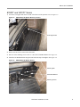
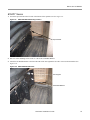
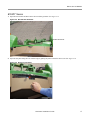
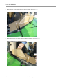
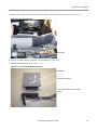
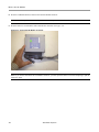
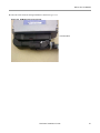
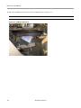
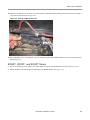
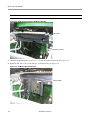
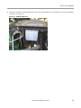
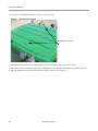
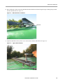
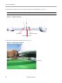
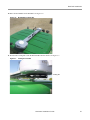
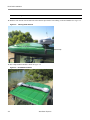
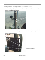
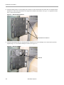
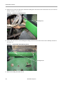
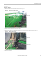
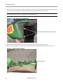
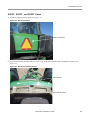
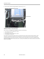
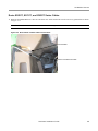
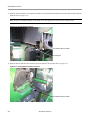
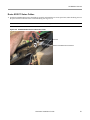
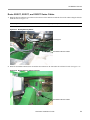
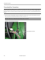
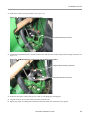
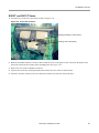
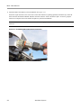
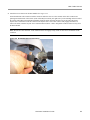
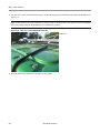
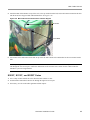
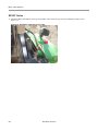
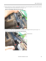
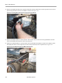
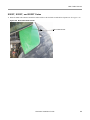
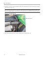
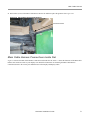
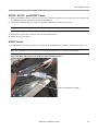
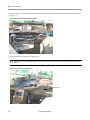
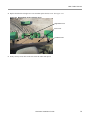
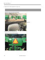
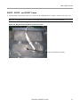
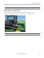
SA Module Harness 8X00T and 8X10T Series 1. Locate the SCU on the rear of the vehicle as shown in Figure 5-26. Figure 5-26 Control Unit Locations Existing Grounding Location Screw Steering Control Unit (SCU) 2. Route the SA Module Harness's “Ground” cable towards the screw on the upper left side of the SCU that holds it to the back of the vehicle and the existing vehicle grounding cable. See Figure 5-26. 3. Remove the screw with a #3 Phillips screwdriver. 4. Clean the area on the SCU housing from dirt and rust where the screw comes in contract with it. 5. Attach the “Ground” connector to the SCU and secure with the screw that was removed in Step 3. Hardware Installation Guide 57 SA Module Harness 8X20T Series 1. Locate the SCU on the rear of the vehicle as shown in Figure 5-27. Figure 5-27 Control Unit Locations Steering Control Unit (SCU) Existing Grounding Location Screw 2. Route the SA Module Harness's “Ground” cable towards the screw on the lower left side of the SCU that holds it to the back of the vehicle and the existing vehicle grounding cable. See Figure 5-27. 3. Remove the screw with a #3 Phillips screwdriver. 4. Clean the area on the SCU housing from dirt and rust where the screw comes in contract with it. 5. Attach the “Ground” connector to the SCU and secure with the screw that was removed in Step 3. 58 AutoSteer System SA Module Harness 9X00T and 9X20T Series 1. Locate the SCU on the rear of the vehicle as shown in Figure 5-28. Figure 5-28 Control Unit Locations Steering Control Unit (SCU) Existing Grounding Location Screw 2. Route the SA Module Harness's “Ground” cable towards the screw on the lower left side of the SCU that holds it to the back of the vehicle and the existing vehicle grounding cable. See Figure 5-28. 3. Remove the screw with a #3 Phillips screwdriver. 4. Clean the area on the SCU housing from dirt and rust where the screw comes in contract with it. 5. Attach the “Ground” connector to the SCU and secure with the screw that was removed in Step 3. 8X30T and 9X30T Series The SCU on the 8X30T and 9X30T are located in the same place. However, the rear compartments of both series look slightly different. For simplicity, this installation manual only shows the controller compartment of the 8X30 series. Follow the same procedure for both series and disregard any differences the pictures show. Hardware Installation Guide 59 SA Module Harness 1. Locate the SCU on the rear of the vehicle as shown in Figure 5-29. 2. Route the SA Module Harness ground cable towards the vehicle’s SCU. 3. Remove the grounding screw on the SCU with a T15 bit socket and ratchet. See Figure 5-29. Figure 5-29 Removing Grounding Screw 4. Attach the SA Module grounding cable to the SCU using the screw removed in Step 3 and an M8 flat washer (from the kit). 5. Tighten the screw and grounding wire securely. See Figure 5-30. Figure 5-30 SA Module Ground Wire Attached Ground Wire Attached 60 AutoSteer System Main Cable Harness Main Cable Harness This Main Cable Harness section contains the following sub-sections: • • • Roof Module • All models • 8X00T, 8X10T, and 8X20T Series • 8X30T Series • 9X00T, 9X20T, and 9X30T Series Main Cable Harness Connections Inside Cab SA Module Harness • 8X00T, 8X10T, and 8X20T Series • 8X30T Series • 9X00T, 9X20T, and 9X30T Series Roof Module This Roof Module section contains the following sub-sections: • • • • All models 8X00T, 8X10T, and 8X20T Series 8X30T Series 9X00T, 9X20T, and 9X30T Series All models Depending on the vehicle series, the Main Cable Harness will need to be routed differently into the back of the cab through the wire access port. First perform the steps in this section and then follow the instructions in the relevant series section for the vehicle where the AutoSteer system is being installed. Hardware Installation Guide 61 Main Cable Harness 1. Attach the Main Cable Harness to the Roof Module. See Figure 5-31. Orient the 12-pin connector so the word “TOP” on the cable connector is pointing upwards (towards the sky). Insert the cable connector into the Roof Module. Push the connector in until it “clicks” and locks in place. To remove, grasp the connector to compress the two side latches and pull away from the Roof Module. Note: Do not force the connector. If the connector does not engage easily, check for the correct orientation of the connector. Figure 5-31 Roof Module Main Cable Harness Connection 62 AutoSteer System Main Cable Harness 2. Attach the LAN connector to the Roof Module. See Figure 5-32. Orient the Ethernet cable connector with the connector under the receiver so the contacts on the cable connector are pointing towards the back of the vehicle. (This will usually be towards your right side if you are standing on the left side of the vehicle and looking towards the Roof Module.) Slide the cable connector into the receiver and rotate the plastic bayonet sleeve clockwise to lock the connector. The bayonet sleeve will “click” when it fully engages and locks. To remove the cable, rotate the bayonet sleeve counterclockwise until it “clicks” and pull the connector down or away from the Roof Module. Note: Do not force the connector. If the connector does not engage easily, check for the correct orientation of the connector. Figure 5-32 Roof Module Ethernet Connection Hardware Installation Guide 63 Main Cable Harness 3. Use cable ties to secure the Main Cable Harness to the Roof Rail using the holes drilled into the back of the Roof Rail. See Figure 5-33. Note: Do not attach the cable ties around the top or bottom parts of the Roof Rail as this will prevent the Roof Module from freely sliding along the Roof Rail when it is installed and removed. Figure 5-33 Cable Ties on Roof Module Bracket Rail Cable Ties 4. Route the Main Cable Harness down the right rear cab support. 64 AutoSteer System Main Cable Harness 5. Attach the Main Cable Harness on top of the roof, to the top window bracket bolt, and to the bottom window bracket bolt with the metal wire clips provided with installation kit. See Figure 5-34. Figure 5-34 Main Cable Harness Routed Down Cab Rear Support 8mm Bolt 10mm Bolts 6. Use an 8mm socket and ratchet for the bolt on top of the cab and a 10mm socket and ratchet for the two window bracket bolts. Note: Depending on the vehicle series, the Main Cable Harness will need to be routed differently into the back of the cab through the wire access port. Follow the instructions in the relevant series section for the vehicle where the AutoSteer system is being installed. 8X00T, 8X10T, and 8X20T Series 1. Leave a loop of cable outside the cab to allow the back window to close. 2. Feed the Main Cable Harness into the cab through the right wire access port. 3. If necessary, cut a slit in the rubber grommet and then replace. Hardware Installation Guide 65 Main Cable Harness 8X30T Series 1. Attach the Main Cable Harness to the top of the fender with a metal wire clip. Use the #3 Phillips screwdriver. See Figure 5-35. Figure 5-35 Attach Main Cable Harness to Fender 66 AutoSteer System Main Cable Harness 2. Starting with the power connector, feed all the Main Cable Harness connectors through the space on the outside of the cab, under the tubing, and into the space behind the seat. See Figure 5-36. Figure 5-36 Routing Main Cable Harness Into the Frame 3. Pull all the excess Main Cable Harness into the cab and route the cable through the cab access port. See Figure 5-37. Figure 5-37 Pull Excess Main Cable Harness Through Cab Frame Cab Access Port Hardware Installation Guide 67 Main Cable Harness 4. Route the SA Module data and power connectors behind the existing controller box from the right side to the left (left to right if facing backwards) where the SA Module is mounted. See Figure 5-38. Figure 5-38 Routing Main Cable Harness Connectors to SA Module 5. Route the SA Module Harness's “Armrest Switch” cable from the left side of the cab to the right behind the controller where the SA Module data and power cables were just passed. 6. Gather the SA Module Harness's “Armrest Switch” cable and the Main Cable Harness's Vehicle Power, Display Comm, and Display Eth cables out the far right side (left side if facing backwards) of the compartment. See Figure 5-39. Figure 5-39 Route External Switch and Main Cable Harness 68 AutoSteer System Main Cable Harness 9X00T, 9X20T, and 9X30T Series 1. Route the Main Cable Harness beneath the fender and above the fuel tank towards the back panel area. See Figure 5-40. Figure 5-40 Route Cable Under Fender Main Cable Harness Hardware Installation Guide 69 Main Cable Harness 2. Route all the connectors except the SA Module data and power cables behind the fuel vent line and then up into the right side of the cab. See Figure 5-41. Note: The picture shows the back of a 9X20 Series vehicle. The 9X30 Series is slightly different. The picture also shows the SA Module Harness's “Armrest Switch” cable being led into the cab. This harness connection is optional. Figure 5-41 Route Cables Into Cab Main Cable Harness 3. Allow the SA Module data and power cables to lead down the back of the vehicle for now. 70 AutoSteer System Main Cable Harness 4. Pull 6 inches (15cm) of the Main Cable Harness into the cab and then replace the grommet. See Figure 5-42. Figure 5-42 Cab Feedthrough Grommet Replaced Grommet in Place Main Cable Harness Connections Inside Cab Figure 5-43 shows the Main Cable Harness connections used inside the cab. Table 5-1 shows the functions of the Main Cable Harness cab connectors. Refer to your Display user manual for instructions on connecting the Main Cable Harness connections shown to the correct ports and harnesses on the Display and Display cables. Hardware Installation Guide 71 Main Cable Harness Figure 5-43 Main Cable Harness Cab Connections Table 5-1 Cab Main Cable Harness Connector Functions Main Cable Harness Connector Connector Function DISPLAY ETH Display Ethernet Port (RJ-45) DISPLAY COMM Display Communication Port (DB-9) VEHICLE POWER 12 Volt Power Supplied by Display Harness SAM POWER Power for SA Module SAM DATA Data for SA Module CAN IN Not Used for This Installation CAN OUT Not Used for This Installation SA Module Harness This SA Module section contains the following sub-sections: • • • 72 8X00T, 8X10T, and 8X20T Series 8X30T Series 9X00T, 9X20T, and 9X30T Series AutoSteer System Main Cable Harness 8X00T, 8X10T, and 8X20T Series 1. Route the SA Module Harness's “Data In” and “Power In” connector behind the seat to the right side of the cab below the air conditioning channel and then up to the Main Cable Harness. 2. Connect the SA Module Harness's “Data In” to the Main Cable Harness's “Data Out” connector. Note: The SA Module Harness's “Power Out” connection is not used in this installation. 3. Neatly coil any excess cable in the cab. Secure all cables with cable ties. 4. Replace the rear access panel. 8X30T Series 1. Attach the Main Cable Harness “Data Out” connector to the SA Module harness “Data In” connector. See Figure 5-44. Note: The SA Module power out connector on the Main Cable Harness is not used in this installation. Figure 5-44 Main Cable Harness and SA Module Harness Data Connection Power Out Connector (not used) Hardware Installation Guide 73 Main Cable Harness 2. Neatly coil the excess cable and secure with a zip tie. Carefully flatten the wires next to the side of the compartment. See Figure 5-45. Figure 5-45 Bundling and Securing Cables 3. Carefully replace the rear panel. See Figure 5-46. Note: Take care to get the SA Module Harnesses neatly tucked behind it. Allow cables gathered in last step to sit inside the cab. Figure 5-46 Replacing Rear Panel Rear Panel 74 AutoSteer System Main Cable Harness 4. Replace both the left and right rear covers and then replace the fuse cover. See Figure 5-47. Figure 5-47 Replace Rear Covers and Fuse Cover Right Rear Cover Fuse Cover Left Rear Cover 5. Neatly coil any excess cable in the cab. Secure all cables with zip ties. Hardware Installation Guide 75 Main Cable Harness 6. Replace the two rubber grommets. See Figure 5-48. Note: If necessary to feed the cables through, cut a slot in the two rubber grommets. Figure 5-48 Replace Feedthrough Grommets Grommets 7. Replace the rear cover. See Figure 5-49. Figure 5-49 Rear Vehicle Cover Replaced 76 AutoSteer System Main Cable Harness 9X00T, 9X20T, and 9X30T Series 1. Attach the Main Cable Harness “Data Out” connector to the SA Module harness “Data In” connector. See Figure 5-50. Note: The SA Module power out connector on the Main Cable Harness is not used in this installation. Figure 5-50 Main Harness to SA Module Harness Connection Power Out Connector (not used) Hardware Installation Guide 77 Main Cable Harness 2. Neatly coil the excess cable and secure with a cable tie. See Figure 5-51. Note: Figure 5-51 shows the back of a 9X20 model vehicle. The 9X30 series will appear different. Figure 5-51 Securing Excess Cable Excess Cable 3. Replace the rear cover. See Figure 5-52. Figure 5-52 Vehicle Rear Cover Replaced 78 AutoSteer System Power Supply Connection Power Supply Connection The following sub-sections describe basic instructions for connecting the AutoSteer system to available vehicle power sources: • • Cab Power Connection Battery Power Connection Note: Refer to your Display user manual before connecting the AutoSteer system to vehicle power. The AutoSteer Main Cable Harness must be connected to a 3-pin 12V power source. Your Display user manual provides specific instructions for connecting power to the AutoSteer system and specifies the appropriate vehicle power source. Cab Power Connection 1. Locate the 12V power outlet at the rear of the side console on the right side of the cab. See Figure 5-53. 2. Use this 12V accessory power connector only if the Display user manual specifies connecting to power inside the cab. Figure 5-53 Cab 12V Power Outlet Cab Power Connection Main Cable Harness Exiting Cab Battery Power Connection The following sub-sections describe basic instructions for connecting the AutoSteer system to available vehicle power sources: • • 8X00T, 8X10T, 8X20T, and 8X30T Series 9X00T, 9X20T, and 9X30T Series Hardware Installation Guide 79 Power Supply Connection 8X00T, 8X10T, 8X20T, and 8X30T Series 1. Locate the vehicle battery compartment at the front of the vehicle under the radiator space. See Figure 5-54. 2. Remove the three bolts holding the side panels to access the battery. 3. Connect to the vehicle battery only if the Display user manual specifies a direct battery connection. Figure 5-54 Vehicle Battery Location 80 AutoSteer System Power Supply Connection Note: A battery cable is provided with the AutoSteer system when a direct battery connection is required. 9X00T, 9X20T, and 9X30T Series 1. Locate the vehicle battery compartment on the right side of the machine next to the cab. See Figure 5-55. 2. Connect to the vehicle battery only if the Display user manual specifies a direct battery connection. Figure 5-55 Vehicle Battery Location Note: A battery cable is provided with the AutoSteer system when a direct battery connection is required. Hardware Installation Guide 81 Power Supply Connection 82 AutoSteer System 6 Post-Installation Procedures and Information The Post-Installation Procedures and Information chapter provides information in the following sections: • • Create New Vehicle Calibration and Tuning Guidelines Once the entire AutoSteer system, including the Display and Display harnesses, have been installed on the vehicle, the procedures and notes provided in this chapter must be followed to complete the installation and prepare the vehicle for full AutoSteer capabilities. Create New Vehicle Once the entire system has been installed, the operator must first create a new vehicle profile. This configures the system so the User display can properly communicate with the various sensors and components on the vehicle. Follow the procedure below to create a new vehicle. 1. Make sure the User display is not powered ON. 2. Start the vehicle and take it to a clear area (such as an open field) where it can be calibrated. 3. Power up the AutoSteer system. 4. Follow the instructions provided in the Display user manual to create a new vehicle. Calibration and Tuning Guidelines Note: For optimal steering performance, the AutoSteer system must be fully calibrated and then tuned. AutoSteer should kick-out when the driver turns the steering wheel while in AutoSteer mode. If AutoSteer does not disengage when you turn the steering wheel, adjust the Override limit so that it does. Hardware Installation Manual 83 Calibration and Tuning Guidelines 84 AutoSteer System 7 Final Checklist This Final Checklist chapter contains the verifications steps necessary after the installation of the AutoSteer system. Note: The Final Hardware Installation Checklist is on the back of this page. Fill in the checklist after the installation. You should keep a copy of this checklist for future reference when servicing the AutoSteer system. Machine Model: _________________________________ Year: _________ Serial #: _________________________ Customer Name: _______________________________________________________________________________ Location/Address: ______________________________________________________________________________ AutoSteer Installation Kit Part Number: ______________________________________________________________ NOTES ____________________________________________________________________________________________________ ____________________________________________________________________________________________________ ____________________________________________________________________________________________________ ____________________________________________________________________________________________________ ____________________________________________________________________________________________________ ____________________________________________________________________________________________________ Name of Installer: __________________________________________ Date: ________________ Hardware Installation Guide 85 Final Checklist System Installation Checklist 1. Display Bracket installed and all fasteners are tight. 2. Roof Rail and Roof Module are installed and all fasteners are tight. 3. SA Module is installed and all fasteners are tight. 4. All cable ends are connected. 5. All cables are secured with cable ties. AutoSteer Performance Checklist 1. Complete the AutoSteer system calibration. 2. Complete the AutoSteer system tuning. 3. Line acquisition is good. 4. On-line steering is good. 5. Manual override (kick-out) is working. Note: See the Post-Installation Procedures and Information chapter for additional information. 86 AutoSteer System