1
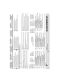
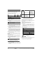
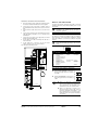
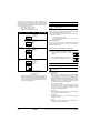
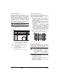
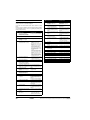
The following table summarizes the required configuration and
thermostat wiring at the terminal block in the switch box. Pump
operation is listed in the third column. The three last columns indicate
whether the following functionality is available on the user interface
(UI) or handled by the thermostat (T):
space heating or cooling on/off (o)
heating/cooling changeover (=)
heating and cooling schedule timers (pr)
No thermostat
Configuration
• SS2-3 = OFF
• wiring: (non)
Terminal block
Pump
operation
Without room thermostat
o
=
pr
determined by
leaving water
temperature (a)
UI
UI
UI
on when space
heating or
cooling is on
UI
UI
UI
H C L N
23 17 15 13
• SS2-3 = ON
• wiring:
Terminal block
• SS2-3 = ON
• wiring:
Terminal block
H C L N
23 17 15 13
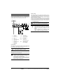
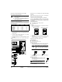
To force continuous pump operation when no room thermostat is
connected do the following:
- set toggle switch SS2-3 to ON,
- short-circuit the terminal numbers 23-17-13 on the terminal
block in the switch box.
When a thermostat is connected to the indoor unit, the pump will
operate continuously whenever there is heating or cooling demand
requested by the thermostat.
(o)
on when
heating
request by
room
thermostat
When no thermostat is connected to the indoor unit, pump operation
will be determined by the leaving water temperature.
With room thermostat
H C L N
23 17 15 13
Heating only
thermostat
To set the pump speed, refer to "Setting the pump
speed" on page 21.
T
-
-
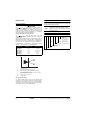
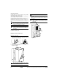
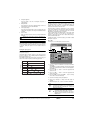
Sanitary water tank installation configuration
■
When no sanitary water tank is installed,
toggle switch SS2-2 should be set to OFF
(default).
ON OFF
Thermostat
NOTE
When a sanitary water tank is installed,
toggle switch SS2-2 should be set to ON.
ON OFF
•
•
•
Pump operation configuration
4 3
2 1
4 3
2 1
th
■
Thermostat with
heating/cooling
switch
• SS2-3 = ON
• wiring:
Terminal block
H C L N
23 17 15 13
on when
heating
request or
cooling request
by room
thermostat
T
T
-
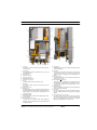
Pre-operation checks
H C
Checks before initial start-up
th
Switch off the
connections.
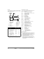
Thermostat contact
Cooling contact
H = Heating contact
L, N = 230 V AC
The pump will stop when space heating/cooling is turned off
or when the water reaches the desired water temperature as
set on the user interface. With space heating/cooling turned
on, the pump will then run every 5 minutes during 3 minutes
to check the water temperature.
th =
C=
(a)
power
supply
before
making
any
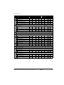
After the installation of the unit, check the following before switching
on the circuit breaker:
1
Field wiring
Make sure that the field wiring between local supply panel and
indoor unit, outdoor unit and indoor unit, indoor unit and valves
(when applicable), indoor unit and room thermostat (when
applicable), and indoor unit and sanitary water tank has been
carried out according to the instructions described in the chapter
"Field wiring" on page 13, according to the wiring diagrams and
according to European and national regulations.
2
Fuses or protection devices
Check that the fuses or the locally installed protection devices
are of the size and type specified in the chapter "Technical
specifications" on page 29. Make sure that neither a fuse nor a
protection device has been bypassed.
3
Earth wiring
Make sure that the earth wires have been connected properly
and that the earth terminals are tightened.
4
Internal wiring
Visually check the switch box on loose connections or damaged
electrical components.
5
Fixation
Check that the unit is properly fixed, to avoid abnormal noises
and vibrations when starting up the unit.
Installation manual
20
EKHBH/X007A+EKSWW150-300V3/Z2
Indoor unit for air to water heat pump and sanitary warm water tank for air to water heat pump system
4PW30818-1