1
ACCESSORIES
TYPICAL
When the
system is used in series
with another heat source (e.g. gas boiler), it shall be made
sure that the return water temperature to the heat
exchanger does not exceed 55°C. Daikin shall not be held
liable for any damage resulting from not observing this
rule.
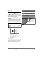
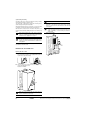
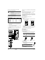
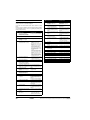
Accessories supplied with the indoor unit
Installation manual
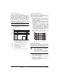
APPLICATION EXAMPLES
1
The application examples given below are for illustration purposes
only.
Operation manual
1
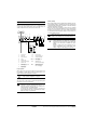
Application 1
Shut-off valve
2
Wall mounting bracket
1
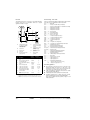
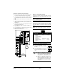
Space heating only application with a room thermostat connected to
the indoor unit.
T
Wiring diagram sticker
(inside indoor unit cover)
1
Drain pan and fixing screws
(only for EKHBX models)
1
Indoor unit cover fixing screw + nylon washer
2
1
2
3
4
5
6
FHL1
7
FHL2
FHL3
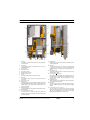
Accessories supplied with the sanitary water tank
(optional)
Thermistor + connection wire (12 m)
1
1
Outdoor unit
6
Collector (field supply)
2
Indoor unit
7
Shut-off valve
3
Heat exchanger
4
Pump
5
Shut-off valve
FHL1..3
Floor heating loop
(field supply)
T
Room thermostat
(field supply)
Pump operation and space heating
Thermistor socket
1
Prewired contactor and circuit breaker
assembly
1
Contactor fixing screw
2
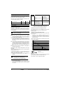
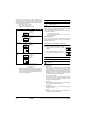
When a room thermostat (T) is connected to the indoor unit, the
pump (4) will operate when there is a heating request from the room
thermostat, and the outdoor unit will start operating to achieve the
target leaving water temperature as set on the user interface.
When the room temperature is above the thermostat set point, the
outdoor unit and pump will stop operating.
EKHBH/X007A+EKSWW150-300V3/Z2
Indoor unit for air to water heat pump and sanitary warm water tank for air to water heat pump system
4PW30818-1
Make sure to connect the thermostat wires to the correct
terminals (see "Connection of the thermostat cable" on
page 16) and to configure the DIP switch toggle switches
correctly (see "Room thermostat installation configuration"
on page 19).
Installation manual
3