1
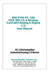
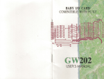
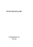
1.4 1.5 1.6 1.7 1.8 1.9 1.10 1.11 1.12 1. 13 1.14 TP UP-NH Line Thermal Printer Printing Buffer Size Printing Commands Operation Format Printer-head Energy Compensation Function Printer-head Protection Function Interface Power Supply Power Supply Control Dimension Weight Operation Environment Chapter 2 2.1 2.2 2.3 User's Manual 2.4 2.5 2.6 Appearance Loading Printing Paper Power ON and OFF 2-3-1 Connecting of Power 2-3-2 Auto Power OFF Indicator and Function Key Connecting of Parallel Interface Connecting of Serial Interface Chapter 3 3.1 3.2 3.3 3.4 3.5 April 1998 3.6 Contents Introduction Chapter 1 1.1 1.2 1.3 1 Features and Specifications Printing Features Printing Paper Printing Character 2 3.7 3.8 3.9 Installation and Operation Printing Commands Summary Paper Feed Command Format Setting Commands Character Setting Commands User-defined Characters Commands 3.5.1 User-defined Characters Form I 3.5.2 User-defined Characters Form II Graphics Printing Commands 3.6.1 Bit Map Graph Setting form I 3.6.2 Bit Map Graph Setting form II Initialization Command Data Control Command Hexadecimal Printing Command Appendix 1 Index of Printing Command 2 2 2 24 25 2 2 3 3 3 3 3 4 4 4 4 5 5 6 8 8 10 11 11 13 15 15 15 16 18 20 20 22 23 23 23 26 27 27 28 Chapter 1 1.1 Printing Features - Printing Method: - Paper Width: - Printing Density: - Printing Speed: - Printing Width: 1.2 Features and Specifications Line direct thermal 57.5 mm ± 0.5 mm 8 dots/mm, 384dots/line 12.5mm/sec. (DC9V 1A) 48mm Printing Paper - Thermal Paper Roll Paper Width: 57.5 mm ±0.5mm OD: 50 mm(max, Build-in) I D: 10 mm(min) Thickness: 53 - 64 g /m2 1.3 Introduction TP UP-NH is a new type of line direct thermal printer. The special features of this printer are small in size, light in weight, low noisy and high in printing quality and reliability. It is suitable for printing receipt of cash register and data records of medical instruments. Printing Character - IBM Character set 2 12 x 24 dots, 1.50 mm(w) x 3.00 mm(h) 8 x 16 dots, 1.00 mm(w) x 2.00 mm(h) 1.4 Data Buffer Size - 10k bytes 1.5 Printing Commands - ESC/P Commands 1.6 Operation - Printing out text in ANK, graph and hexadecimal - Self-test - Paper feed 1.7 Printer-head Energy Compensation Function - Temperature Control: by test of build-in thermal resistor. 24 25 - Voltage Control: by test of voltage 1.8 Printer-head Protection Function - Stop warning for out of paper - Stop warning for printer-head over/under the normal temperature 1.9 Interface - Serial (compatible with RS232) Baud Rate: 1200/2400/4800/9600, selected by DIP switch built-in Handshaking: RTS/CTS or XON/XOFF protocol. Data Structure: 7/8 Data Bits and even, odd or no Parity Bit Connect Socket: D-Sub 25pin (femal in printer side) Signal Level: EIA +/-3V to +/-12V - Parallel (compatible with PC Printer port) Handshaking: BUSY or ACK protocol Connect Socket: D-Sub 25pin (male in printer side) Signal Level: TTL 1.10 Chapter 2 2.1 Installation and Operation Appearance Power Supply - DC9V 1A average printing current 2.6A, non-printing current 80mA. - Power Socket: DC Jack type with center pin φ 2.0mm 1.11 Power Supply Control - Auto Power off Function - Support Push Button and Interface Signal Control 1.12 Dimension - 160 (w) x 106 (d) x 42 (h) mm 1.13 Weight - 350g including paper roll 1.14 Operation Environment - Operating temperature: 5 o - 50o C - Relative humidity: 5 - 85% RH 24 25 Figure 2-3 Figure.2-1 Appearance 2.2 Loading Printing Paper Paper roll can be put inside the case, Loading paper as follows: 1. 2. Cut the paper end like figure 2-4 below. - for paper roll placed inside the case: Insert the paper end deep-down into paper in slot on rear of printer mechanism like figure 2-5. Figure 2-6 is not correct. - for paper roll hold outside the case: Insert the paper end through paper in slot on the back of the printer first, then repeat the action above. push the removable upper cover plate forward till its off the printer like figure 2-2 below, figure 2-3 is not correct. Figure 2-4 Figure 2-2 Figure 2-5 3. 24 Figure 2-6 Lift the lever of the print mechanism and push the paper end forward out of the mechanism. Turn on the power. Power indicator flashing while press SEL button. Hold the LF button, paper will automatically move upwards to paper out slot on top of printer mechanism for certain length , then release the button. 25 4. Pull the paper out through paper out slot on upper cover plate and then close the plate like figure 2-7 below. 400 IF (INP (prtr-1) AND &H98) <>&H98THEN 400 Figure 2-7 put upper cover plate back to the printer 2-3 Power On and OFF This printer provides auto power cut off function to save energy. : Loop if check the printer is BUSY. : Normal printing procedure. 500 . prtr-1 BIT3: BIT4: BIT7: . . . . status register of parallel interface 0, printer error; 1, printer normal 0, printer off line; 1, printer on line 0, printer busy; 1, printer not busy prtr control register of parallel interface BIT2: 0, initialize printer; 1, normal setting BIT3: 0, make printer off line; 1, normal setting 2.3.1 Connecting of Power After connecting the power supply, there are two methods of power connecting namely: 1. by push button; 2. by interface. 1. By Push Button. There are two push buttons on the control panel namely SEL & LF. Press SEL button, power indicator will be in red to indicate the printer is on power.. 2. By Interface - Using Parallel Interface. The interface signal INIT is negative pulse signal and will remain for at least 3ms to ensure power on. Power Indicator turns in red to signal the printer is on power. Wait another 600ms to initialize printer before sending data. - Using Serial Interface. The interface signal DTR is EIA standard. It is logical level from “1” to “0 ” and remain at least 3ms to ensure power connection. Power indicator turns in red to signal the printer is on power. Wait another 600ms to initialize printer before sending data. 3. Example of Using Parallel Interface (for PC) Basic Formal 100 DEF SEG=&H40 Explanation : Bottom of BIOS database. : Get base address of LPT1. : Initialize printer by negative signal through INIT. 200 prtr=PEEK (9) *256+PEEK (8) +2 300 OUT prtr, 8 24 4. Example of Using Serial Interface (for PC) Basic Program 100 baseaddress = &H2f8 200 OUT baseaddress +4, &H1 Explanation : Set base address of serial port. : &H3F8 for COM1 and &H2F8 for COM2. : DTR (data terminal ready) set high. 300 IF (INP (baseaddress+6) AND &HB0) <> &HB0 THEN 300. : Loop if check printer is not READY. 400 . : Execute normal printing procedure . . . . baseaddress+4: Control register of modem of the PC serial port COM1 or COM2. BIT0: DTR (data terminal ready) set 1 for valid. baseaddress +6 Status register of modem of the PC serial port 25 BIT4: BIT5: BIT7: 2.3.2 COM1. CTS allow for transmitting” input high (ok). DSR data ready” input high (ok). RLSD receipt route signal testing” input high(ok). Auto Power Off This printer provides auto power cut off function. If no paper feed and printing function performed more than 10 seconds, power will be automatically cut off. 2.4 Indicator & Function Key There are two indicators and two switch buttons on the panel of TP UP-NH printer. Power Indicator marked with P and Status indicator marked with SEL. When SEL indicator in light or flash , it means printer is wrong otherwise means printer is normal. For power connection, press SEL button; for paper feed press LF button. see figure 2-8 below: 1. The Pin Assignment of DB-25 is shown as follows: PinN o 1 2 3 4 5 6 7 8 9 10 Signal I/O Description /STB D0 D1 D2 D3 D4 D5 D6 D7 /ACK In In In In In In In In In Out 11 BUSY Out 12 PE Out 13 14 15 SLCT ------/ERRO R /INIT ------- Out ----Out Strobe pulse, to read data. Reading occurs at falling edge. Data line: D0 Data line: D1 Data line: D2 Data line: D3 Data line: D4 Data line: D5 Data line: D6 Data line: D7 Acknowledge pulse. Printer is ready to accept data. It takes no less than 10µs to change from high level to low level. High level signal indicates that the printer is Busy and can not receive data while low level is able to receive data. High level signal indicates that paper running out. Low level signal indicates otherwise. Selection, pull up to 5V. No connection. Pull up to 5V In ----- Low level signal (no less than 3ms) for control of printer power. No connection. ------- ----- Grounding. 16 17 18 25 2. The signal timing chart in parallel port is as follows: Figure 2-8 1. Self-test To start self-test, press and hold down LF button and SEL button as well while power on, when power indicator light, release both buttons, then self-test sample will be printed. 2. Paper feed Press and hold down LF button to start paper feeding and release it to stop paper feeding. 2.5 Connecting of Interface (parallel port) Figure 2-9 Signal timing chart of parallel port 2.6 Connecting of Interface (serial port) TP UP-NH adopts serial port which is compatible with RS232C for DB-25 socket (female type in printer side) TP UP-NH adopts DB-25 parallel port which is compatible with PC ′s printer port. 1. DIP Switch Setting K1-K6 for setting of baud rate, data bit, stop bit and parity. Default settings are all on off position, users can change setting according to the following tables: 24 25 Baud Rate (BPS) ON ■ ■ OFF □ □ 1200 1 2 ON □ ■ OFF ■ □ 2400 ON ■ □ OFF □ ■ 4800 ON □ □ OFF ■ ■ 9600 DIP Switch Parity Check ON ■ □ OFF □ ■ 4 5 ON □ ■ OFF ■ □ ON □ □ OFF ■ ■ ON ■ □ OFF □ ■ ON □ ■ OFF ■ □ ON □ □ OFF ■ ■ Handshaking ON □□□□□□ OFF □□■□□□ 1 2 3 4 5 6 ON □□■□□□ OFF □□□□□□ 1 2 3 4 5 6 XON/XOFF □ ■ 6 □ ■ □ ■ ■ □ ■ □ ■ □ 8 bit odd parity 8 bit even parity 8 bit non-parity 7 bit odd parity 7 bit even parity 7 bit non-parity Default Setting ON □□□□□□ OFF ■■■■■■ 1 2 3 4 5 6 RTS/CTS Figure 2-10 DIP Switch Setting Pin Assignment of DB25 Pin No. 2 3 Signal TXD RXD Source Host Printer 5 CTS Printer 7 20 GND DTR Printer Host Description Printer receive data from host. Printer transmit data. Printer transmit XON/XOFF code to host while in use of handshaking of XON/XOFF. There are two states of this signal, "Mark" and "Space". "Mark" indicates that the printer is busy and unable to receive data; "Space" indicates that printer is ready to receive data. Signal ground In SPACE” status for not less than 3ms, for control of printer power. Chapter 3 3.1 Printing Commands Summary TP UP-NH provides ESC/P commands: 1. define format 2. enlarge characters 3. print bit map graphs 4. choice character sets 5. define user-defined characters 6. others Each command is described in following format: Printing command Function Format: ASCII: the standard ASCII characters sequence. Decimal: the decimal numbers sequence. Hexadecimal: the hexadecimal numbers sequence. Explanation: What the command does and how to use it. 3.2 Paper Feed Commands LF Format Line Feed ASCII : LF Decimal : 10 Hexadecimal: 0A Explanation: Print data in buffer of the printer and feed one line forward. Feed one line forward only if no data in buffer of the printer. 24 25 HT command will not execute if the current print position exceeds the last horizontal tab. ESC J Format 'n' Dot Line Feed ASCII : ESC J n Decimal : 27 74 n Hexadecimal: 1B 4A n Explanation: print data in buffer of the printer and feed 'n' -dot line forward. The value of n is between 0 and 255. Line space will be automatically adjusted when using commands ESC V & ESC W for enlarge characters. ESC 1 Format Set n’ dot line spacing ASCII : ESC 1 n Decimal : 27 49 n Hexadecimal: 1B 31 n Explanation: The line spacing is set to n dot lines for future Line Feed command. The value of n is between 0 and 255. Default setting n=10 for text printing, n=0 for bit map printing when using ESC K command. 3.3 ESC f Format Print Blank Characters or Lines ESC f m n 27 102 m n 1B 66 m n ASCII : Decimal : Hexadecimal: Explanation: If m=0, command ESC f NUL will print n blank characters. The value n should be within the line width of the printer (see command ESC D in the chapter). If m=1, command ESC f n will print n blank lines. The value of n should be within the range between 0 to 255. ESC I Format Set Left Margin ASCII : ESC I n Decimal : 27 108 n Hexadecimal: 1B 6C n Explanation: This command sets start printing position as n character from left. The value of n should be within the line width of the printer. For character set A, n=32 and character set B, n=48. Default value n=0, This means no left margin. The command sets an absolute position and is not affected by character enlarge command ESC U or ESC W. Format Setting Commands ESC D Format Set Horizontal Tabs ESC D n1 n2 ... NUL 27 68 n1 n2 ... 0 1B 44 n1 n2 ... 00 ASCII : Decimal : Hexadecimal: Explanation: The tab positions are entered as n1 , n2 and so on. These n1 , n2 should be within the line width of the printer. For character set A 12x24 dots, the maximum value n=32; for character set B 8x16 dots, the maximum value n=48. NUL character is added to indicate the end of command. All settings can be cleared by using command ESC D NUL. HT Format Horizontal Tab ASCII : HT Decimal : 9 Hexadecimal: 09 Explanation: The printing position is advanced to the next horizontal tab. 24 3.4 Character Setting Commands ESC U Format Enlarge Width ESC V Format Enlarge Height ASCII : ESC U n Decimal : 27 85 n Hexadecimal: 1B 55 n Explanation: Characters or graphics following this command are printed at n times normal width. The value n should be in the range 1- 2. Default value n=1, that means normal width. ASCII : Decimal : Hexadecimal: Explanation: ESC V 27 86 1B 56 25 n n n Characters or graphics following this command are printed at n times normal height. The value n should be within the range 1-2. Default value n=1, that means normal height. ESC W Format Enlarge Width & Height ASCII : ESC W n Decimal : 27 87 n Hexadecimal: 1B 57 n Explanation: Characters or graphics following this command are printed at n times normal width and height. The value n should be in the range 1-2. Default value n=1, that means normal width and height. Decimal : 14 Hexadecimal: OE Explanation: Characters following this command on the same line n the print buffer are printed at twice their normal width. The command is canceled by a Carriage Return or using DC4 command. DC4 Cancel Double-width Printing Format ASCII : DC4 Decimal : 20 Hexadecimal: 14 Explanation: Double-width printing is canceled if it has been set using SO. This command does not cancel enlarge width printing selected using ESC U or ESC W. ESC c Format ESC Format Turn Underline on/off ASCII : ESC n Decimal : 27 45 n Hexadecimal: 1B 2D n Explanation: Underlining is turned on if n=1, all characters are underscored including spaces. Underline is turned off if n=0. ESC 6 Format Select Font A ASCII : ESC 6 Decimal : 27 54 Hexadecimal: 1B 36 Explanation: Characters following this command are printed using the Font A. There are two fonts available in the TP UP-NH printer. Font A is selected at power on or on ESC @ command. ESC 7 Format Select Font B ASCII : ESC 7 Decimal : 27 55 Hexadecimal: 1B 37 Explanation: Characters following this command are printed using the font B (see ESC 6). SO Format Select Double-width Printing ASCII : SO 24 Turn Inverse Printing on/off ASCII : ESC c n Decimal : 27 99 n Hexadecimal: 1B 63 n Explanation: Inverse printing is turned on if n=1; inverse printing is turned off if n=0. Default value n=0 3.5 User Defined Characters Commands There two forms of user defined characters which can be recognized by printer automatically. 3.5.1 User Defined Characters Form 1 Support user defined characters for 101 DPI horizontal and 68 DPI vertical. Compatible with TPuP-T printer. ESC & Format Define User Defined Characters & m n1 n2 ... n6 38 m n1 n2 ... n6 26 m n1 n2 ... n6 ASCII : ESC Decimal : 27 Hexadecimal: 1B Explanation: This command allows a character to be defined. The value m is the code of this user-defined character and ranges from 32 to 255. The value n1,n2,...n6 are codes for structure defined characters. Character size is 6 x 8 dot matrix. That means there are six codes, each code define one row of character for 8 rows. User-defined characters are stored in printer RAM until power off. It can print out according to 101 DPI horizontal and 68 DPI vertical. If many ESC & commands use same m value, only the last one is effective. The maximum number of user-defined characters is 32. Also 25 see ESC% and ESC: commands. ASCII : Decimal : Hexadecimal: Explanation: This command is used to replace font characters n with user-defined characters m. m1, m2, ... mk are codes of user-defined characters. n1, n2, ... nk are codes of the characters in the current font - the replaced characters. The values m and n should be in the range 32 to 255. The subscript k ranges from 1 to 32. The maximum number of replaced characters is 32. The NUL character is added to indicate the end of the commands. Also refer ESC & ESC: commands. Explanation: This command allows characters to be defined. s = 3, 32< = n < m < = 126, 0 < = a < = 12 (for font A), 0 < = a < = 9 (for font B), 0 < = p < = 255. - s stands for number of bytes in vertical. S = 3. - n stands for starting ASCII code of user-defined character. - m stands for ending ASCII code of user-defined character. When define only one character n=m. The maximum number of user-defined characters is 50 and the maximum number of times for different user-defined characters is 50 for each Font A & Font B. - a stands for number of dots horizontal. - p stands for data of user-defined characters, there are s x a character codes for each character for defining m-n+1 characters. - user-defined characters are valid till re-definition or return back to start position or power off. ESC : Format 3.6 Graphics Printing Commands 3.6.1 Bit Image Graph Setting Form I ESC % Format Replace with User Defined Characters ESC % m1 n1 m2 n2 ... mk nk NUL 27 37 m1 n1 m2 n2 ... mk nk 0 1B 25 m1 n1 m2 n2 ... mk nk 00 Reinstate the Font Characters ASCII : ESC : Decimal : 27 58 Hexadecimal: 1B 3A Explanation: The command reinstates the original characters in the font replaced by user-defined characters using ESC % command. User-defined characters, however, are not deleted from the RAM in printer and may be brought back again with ESC %. 3.5.2 User Defined Characters Form 2 Support user defined high density characters for 203 DPI horizontal and vertical. Compatible with printer using ESC/POS commands. .ESC % Select User Defined Characters Format ASCII : ESC % n Decimal : 27 37 n Hexadecimal: 1B 25 n Explanation: This command can select /cancel user-defined characters. n should be in the range 0 -1. If n =<00000001> B the user-defined characters are selected. If n=<00000000> B the regular characters are selected. Default setting is regular characters. Using ESC & command to define user-defined characters. ESC & Format Define User Defined Characters ASCII : ESC & s n m [a [p] s x a ]m-n+1 Decimal : 27 38 s n m [a [p] s x a ]m-n+1 Hexadecimal: 1B 26 s n m [a [p] s x a ]m-n+1 24 Only support bit map 101 DPI horizontal and 68 DPI vertical. ESC K Format Bit Image Graph Printing ASCII: ESC K n1 n2 ... data ... Decimal: 27 75 n1 n2 ... data ... Hexadecimal: 1B 4B n1 n2 ... data ... Explanation: This command is designed to print n1 x 8 bit image. The width of this bit map is n1 + n2 x 256 dots and the height is 8 dots. Each column has 8 dots and can be presented by a byte (8 bits and bit 7 presents the highest dot in the column). The data are the bytes of relative columns in the graphics sequential from left to right.. The number of bytes should be n1 + n2 x 256. 3.6.2 Bit Map Graph Setting Form II ESC * Format Set Bit Map ASCII : ESC * m n1 n2 [d] k. Decimal : 27 42 m n1 n2 [d] k Hexadecimal: 1B 2A m n1 n2 [d] k Explanation: This command is for setting bit map by using m and n1,n2. The bit map graph can be printed by either followed LF command or the width of the graph exceeds the width of the line. So, this command allows to print both characters and graphics in same line. m = 0, 1, 32, 33. n1 = 0 - 255, n2 = 0 - 3, d = 0 - 255. k = n1 + 256 x n2 (m = 0, 1) 25 k = (n1 + 256 x n2) x 3 (m = 32,33) - The number of horizontal dots of the graphics is n1 + 256 x n2. - The width of bit map data should be within the line width, excess parts will be ignored. - d presents bit map data, and k presents number of bit map data. m for the setting of bit map. The definition of m is shown as below: m mode vertical horizontal dot dot density dot density max dot 0 8 dot single 8 68 DPI 101 DPI 192 density 1 8 dot double 8 68 DPI 203 DPI 384 density 32 24 dot single 24 203 DPI 101 DPI 192 density 33 24 dot double 24 203 DPI 203 DPI 384 density GS * Format Define Down-load Bit Map Graph * n1 n2 [d] k. 42 n1 n2 [d] k 2A n1 n2 [d] k ASCII : GS Decimal : 29 Hexadecimal: 1D Explanation: This command sets a down-load bit map graph. n1 = 1 - 48, n2 = 1 - 255, n1 x n2 < 9600, k = n1 x n2 x 8. - d presents bit map data. - The horizontal size of this graph is n1 x 8 dots and vertical is n2 x 8 dots - This setting will be lost while resetting or return back to start position. Bit Map format is showing as follows: 24 GS / Format Print Down-load Bit Map Graph ASCII : GS / n Decimal : 29 47 n Hexadecimal: 1D 2F n Explanation: This command print out the down-load bit map graph set by command GS *. n for selection of bit map. n = 0 - 3. The relative graph sizes are listed as follows: n graph size density in vertical density in horizontal 0 normal 203 DPI 203 DPI 1 double width 203 DPI 101 DPI 2 double height 101 DPI 203 DPI 3 double height & width 101 DPI 101 DPI ESC ′ Format Print Curving Lines ′ m n1 n1′ ... nk nk′ CR 39 m n1 n1′ ... nk nk′ CR 27 m n1 n1′ ... nk nk′ CR ASCII : ESC Decimal : 29 Hexadecimal: 1B Explanation: This command is designed to print curving graphic lines along with the paper feed direction. (vertically). The value m is the number of lines to be printed, and should be within the range of 1 to 384. In a horizontal line, there are m dots of m curving line. The value n1, n1′, n2, n2′ ... nk, nk′ represents the position of dot of m line. The quantity of nk should be equal m and each nk should be fall on the largest dot in each line. The last CR (carriage return) lets printer print this one horizontal dot line out and carriage return to next dot line. So a set of horizontal dot lines will be printed out to form m curving graphic lines. base on the data of n1, n1′, n2, n2′, ..., nk, nk′.’. 25 3.7 Initialization Command ESC @ Format Initialize Printer ASCII : ESC @ Decimal : 27 64 Hexadecimal: 1B 40 Explanation: This command initialize printer in following aspects: - clear data in printing buffer. - reinstate default value. - select internal character font A. - clear user defined characters. Appendix 1 Index of Printing Command 3.8 Data Control Command CR Format Carriage Return ASCII : CR Decimal : 13 Hexadecimal: OD Explanation: When a Carriage Return is sent to the printer, any data in the buffer is printed and paper is fed one line. Same as LF command. NUL Format Null ASCII : NUL Decimal : 0 Hexadecimal: 00 Explanation: NUL is used as the final code in some commands such as ESC B, ESC D. NUL command is ignored by printer when used alone. 3.9 Hexadecimal Printing Command ESC ” Format Turn Hexadecimal Dump Printing on/off ASCII: ESC ” n Decimal: 27 34 n Hexadecimal: 1B 22 n Explanation: 24 Hexadecimal Dump print mode is turned on if n = 1, and turned off if n = 0. If you execute programs or list program in Hexadecimal Dump print mode, all data sent from the host computer will be printed out in hexadecimal. Printing in the Hexadecimal Dump mode is performed only when the printer is in the line buffer-full state. Decimal Hexadecimal Command 0 00 NUL 9 09 HT 10 0A LF 13 0D CR 14 0E SO 20 14 DC4 27 34 1B 22 ESC ” n 27 38 1B 26 ESC & m n1 n2..n6 27 37 1B 25 ESC % m n1 n2 ..mk nk NUL 27 42 1B 2A ESC * 27 58 1B 3A ESC : 27 37 1B 25 ESC % n (n<2) 27 38 27 39 27 45 27 49 27 54 27 55 27 64 27 68 27 74 27 75 27 85 27 87 27 86 27 99 27 102 27 108 29 42 29 47 Description Page No. Nil Horizontal Tab Line Feed Carriage Return Select Double-width Printing Cancel Double-width Printing On/off Hexadecimal Printing Define User-defined Characters Replace with User Defined Characters Set Bit Map Graph Reinstate the Font Characters Selection of self-defined Character Sets 1B 26 ESC & s n m Define User-defined [a[p]sxa]m-n+1 Characters 1B 27 ESC ′m n1 n1′ Print Curving Lines ....nk nk′’ CR 1B 2D ESC - n On/off Underline Printing 1B 31 ESC 1 n Set n’ dot line Spacing 1B 36 ESC 6 Select Character set A 1B 37 ESC 7 Select Character Set B 1B 40 ESC @ Initial the Printer 1B 44 ESC D Set Horizontal Tab 1B 4A ESC J n Line Feed 1B 4B ESC K n1 n2 ...data Bit Map Graph Printing 1B 55 ESC U n Character Width Enlarge 1B 57 ESC W n Character Width & Height Enlarge 1B 56 ESC V n Character Height Enlarge 1B 63 ESC c n On/Off Inverse Printing 1B 66 ESC f m n Print Blank Characters or Lines 1B 6C ESC I n Set Left Margin 1D 2A GS * n1 n2 [d] k Define Down-load Bit Map Graph 1D 2F GS / n Print Down-load Bit Map graph 25 27 17 15 27 19 20 27 20 21 23 21 22 22 26 19 16 19 19 26 16 16 23 18 18 18 20 17 17 24 25