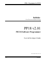
1
PP18 – Programmer for PIC18
Softelec
Free Electronic & Software Design
PP18 v2.01
PIC18 Software Programmer
User & Developer Guide
2003, October 20th – Rev 1.00
1 / 27
10/23/2003
PP18 – Programmer for PIC18
TO ANY PP18 USER
Distribution: This file is part of PP18.
PP18 is free software; you can redistribute it and/or modify it under the terms of the GNU General License
as published by the Free Software Foundation; either version 2, or (at your option) any later version.
PP18 is distributed in the hope that it will be useful, but WITHOUT ANY WARRANTY without even the
implied warranty of MERCHANTABILITY or FITNESS FOR A PARTICULAR PURPOSE. See the GNU
General Public License for more details.
You should have received a copy of the GNU General Public License along with PP18; see the file
COPYING.txt. If not, write to the Free Software Foundation, 59 Temple Place - Suite 330, Boston, MA
02111-1307, USA.
2 / 27
10/23/2003
PP18 – Programmer for PIC18
Table of content
1
APPLICATION OVERVIEW........................................................................................................................... 5
1.1
1.2
1.3
1.4
1.5
2
PRESENTATION ................................................................................................................................................. 5
CURRENT RELEASE ........................................................................................................................................... 5
SUPPORTED DEVICES ........................................................................................................................................ 5
SUPPORTED PROGRAMMERS ............................................................................................................................. 5
PERFORMANCE ................................................................................................................................................. 6
INSTALLATION PROCEDURE ..................................................................................................................... 7
2.1
2.2
2.3
2.4
2.5
3
MINIMUM CONFIGURATION .............................................................................................................................. 7
ZIP FILE CONTENT ............................................................................................................................................ 7
W95 / W98 INSTALLATION............................................................................................................................... 7
W2000/ NT / XP INSTALLATION ...................................................................................................................... 7
WINDOWS REGISTRY ........................................................................................................................................ 7
PP18 USER GUIDE ........................................................................................................................................... 8
3.1
3.2
3.3
3.4
3.5
3.6
3.7
3.8
3.9
3.10
3.11
3.12
3.13
3.14
3.15
4
SELECT DLL..................................................................................................................................................... 8
ABOUT THE DLL .............................................................................................................................................. 8
DOWNLOAD FROM PIC ..................................................................................................................................... 8
OPEN AN HEX FILE .......................................................................................................................................... 9
SAVE AN HEX FILE AS...................................................................................................................................... 9
SELECT THE CURRENT DISPLAY ........................................................................................................................ 9
UPLOAD TO PIC................................................................................................................................................ 9
POPUP MENU ..................................................................................................................................................... 9
HARDWARE SETTINGS .................................................................................................................................... 10
ADVANCED SETTINGS ................................................................................................................................ 10
CONFIGURATION BITS ................................................................................................................................ 11
SELECT PLUG-IN......................................................................................................................................... 11
BULK ERASE .............................................................................................................................................. 11
PIC AUTODETECTION................................................................................................................................. 11
ABOUT THE APPLICATION .......................................................................................................................... 11
DEVICE MIGRATION ................................................................................................................................... 12
4.1
4.2
4.3
4.4
4.5
5
REQUIREMENTS .............................................................................................................................................. 12
DLL ARCHITECTURE OVERVIEW..................................................................................................................... 12
DLL INTERFACE ............................................................................................................................................. 12
CUSTOMISING DLL ........................................................................................................................................ 12
VALIDATION TEST PLAN ................................................................................................................................. 12
HARDWARE MIGRATION........................................................................................................................... 13
5.1
5.2
6
CUSTOMISING HARDWARE .............................................................................................................................. 13
DEVELOPING WITH A NEW PERIPHERAL .......................................................................................................... 13
TROUBLESHOOTING................................................................................................................................... 14
6.1
6.2
6.3
HARDWARE NOT DETECTED ............................................................................................................................ 14
PIC NOT DETECTED ........................................................................................................................................ 14
PIC18 IS BAD PROGRAMMED .......................................................................................................................... 15
7
REVISION HISTORY ..................................................................................................................................... 16
8
RELATED DOCUMENTATIONS................................................................................................................. 17
3 / 27
10/23/2003
PP18 – Programmer for PIC18
9
CONTACTS AND MAINTAINERS............................................................................................................... 18
10
APPENDICES .................................................................................................................................................. 19
10.1
10.2
10.3
4 / 27
INTERFACE BETWEEN PP18 AND DLL ....................................................................................................... 19
FIRST ACCESS TO THE CHIP INSERTED (EXAMPLE FOR PIC18F458)............................................................ 24
EXAMPLE TO PROGRAM A PIC18FXXX DEVICE .......................................................................................... 25
10/23/2003
PP18 – Programmer for PIC18
1 APPLICATION OVERVIEW
1.1 Presentation
PP18 is freeware, which programs any PIC in the
Microchip PIC18 family. It is distributed under GPL
licence.
PP18 offers a Graphical User Interface to access the
PIC18 memory easily. The application is separated in
2 parts:
! A window common to every PIC18 managed
by the application.
! A specific DLL (Dynamic Loaded Library) for
each PIC in the PIC18 family.
PP18 is running properly under any 32-bit version of
Microsoft Windows.
PP18 should be ported to Linux, but this release does
not yet run under “Unix like” operating systems.
1.2 Current release
The current release is the 2.01. The previous version
(1.00) of PP18 was not able to program any PIC18,
but just PIC18F452 chip. The 1.00 version has
validated the PIC18 access through a parallel port.
The release 2.00 is based on an interface in-between
the main window and the DLL in order to manage
each PIC18 specifically. Indeed Microchip does not
use the same access protocol for every PIC in the
PIC18 family.
1.3 Supported devices
The devices supported by the PP18 release 2.00 are:
PIC18F242
PIC18F248
PIC18F442
PIC18F448
PIC18F252
PIC18F258
PIC18F452
PIC18F458
PIC18F1220
PIC18F1320
PIC18F2220
PIC18F2320
PIC18F2331
PIC18F2431
5 / 27
Available
YES
YES
YES
YES
YES
YES
YES
YES
NO
YES
NO
NO
NO
NO
Tested
YES
NO
YES
NO
YES
NO
YES
YES
NO
YES
NO
NO
NO
NO
PIC18F4220
PIC18F4320
PIC18F4331
PIC18F4431
PIC18F6520
PIC18F6620
PIC18F6720
PIC18F6680
PIC18F8520
PIC18F8620
PIC18F8720
PIC18F8680
YES
NO
NO
NO
YES
YES
YES
NO
NO
NO
YES
NO
YES
NO
NO
NO
NO
YES
YES
NO
NO
NO
NO
NO
PIC18C242 JW/OTP
PIC18C248 JW/OTP
PIC18C442 JW/OTP
PIC18C448 JW/OTP
PIC18C252 JW/OTP
PIC18C258 JW/OTP
PIC18C452 JW/OTP
PIC18C458 JW/OTP
PIC18C1220 JW/OTP
PIC18C1320 JW/OTP
PIC18C2220 JW/OTP
PIC18C2320 JW/OTP
PIC18C2331 JW/OTP
PIC18C2431 JW/OTP
PIC18C4220 JW/OTP
PIC18C4320 JW/OTP
PIC18C4331 JW/OTP
PIC18C4431 JW/OTP
PIC18C6520 JW/OTP
PIC18C6620 JW/OTP
PIC18C6720 JW/OTP
PIC18C6680 JW/OTP
PIC18C8520 JW/OTP
PIC18C8620 JW/OTP
PIC18C8720 JW/OTP
PIC18C8680 JW/OTP
NO
NO
NO
NO
NO
NO
NO
NO
NO
NO
NO
NO
NO
NO
NO
NO
NO
NO
NO
NO
NO
NO
NO
NO
NO
NO
NO
NO
NO
NO
NO
NO
NO
NO
NO
NO
NO
NO
NO
NO
NO
NO
NO
NO
NO
NO
NO
NO
NO
NO
NO
NO
For each PIC18 supported there is a specific DLL
located on the web site of PP18. The DLL filename is
the one of the device.
1.4 Supported programmers
PP18 is designed to access PIC18 through any
peripheral because this job is done by the DLL.
Elsewhere the PIC18 device needs only 5 signals to
be programmed:
! VCC
! VPP
! DATA TO PIC
10/23/2003
PP18 – Programmer for PIC18
!
!
DATA FROM PIC
CLOCK
It is recommended to use SCHAER and SCHAER+
programmers through LPT port. All the free DLL
proposed with PP18 have to be used with SCHAER
type programmer.
The SCHAER+ programmer is a hardware derived
from the famous SCHAER programmer designed to
access the PIC16F84 through the parallel port.
The SCHAER+ version is able to manage the 5
signals described above. It exists in a version with
ZIF 40 pins socket to program PDIP chips and an
ICSP version to program the chip from the PCB itself.
Visit the following web site to get more information
related to SCHAER+ programmer:
http://perso.wanadoo.fr/softelec
1.5 Performance
PP18 is really fast software, capable of programming
the entire memory (code, configuration bits and ID),
reading all the fields programmed and computing the
corresponding checksum in less than 10 seconds in
case of maximum speed settings (32 Kb target).
To do so PP18 uses a DIRECT IO method to address
the LPT port of the PC. The application accesses
directly the IO address even on protected Windows
platforms, thanks to ALLOWIO.exe program from
www.beyondlogic.org.
6 / 27
10/23/2003
PP18 – Programmer for PIC18
2 INSTALLATION
PROCEDURE
Every time you run PP18 the application will look up
the key to take into account the last settings.
2.1 Minimum configuration
Because Windows 2000, NT or XP need kernel
privileges to access directly the IO addresses, PP18 is
not authorized to write and read through the LPT port
(PP18 is running with application privileges).
The minimum configuration required is an i386
processor with 8 Mbytes of memory, and Microsoft
Windows.
Tests have been done with a Intel Celeron processor
at 400 MHz with 128 Mbytes of RAM. Windows 98
and Borland Builder 3.0 have been chosen for
validation and development.
2.2 ZIP file content
Here is a screenshot of the ZIP file content:
2.4 W2000/ NT / XP installation
So it’s necessary to use a kind of bridge to allow an
application to access a resource via the bridge. This is
the job of a driver. To get the same effect without
developing any driver, we can use ALLOWIO.exe
program developed by www.beyondlogic.org.
To execute PP18 under Windows 2000, NT or XP
open a DOS window and find the directory where
PP18_v2_00.zip has been extracted.
Type “Allowio 0x378 PP18.exe” which permits
PP18 to freely access the LPT 1 (0x378), and then
runs PP18.
For a more comfortable use create a batch file in
which you’ll insert the previous command line.
2.5 Windows Registry
All the PP18 settings are stored in the Registry in
order to facilitate the reuse of the application.
The key manipulated by PP18 is located at:
HKEY_CURRENT_USER/Software/PP18
To not disturb PP18 process it is mandatory to not
modify the values of this key. You can read or copy
the content of the key, but never change it.
2.3 W95 / W98 installation
To run PP18 under Windows 95 or 98 you don’t need
any special installation.
In case any value has been changed, terminate the
PP18 application, delete the entire PP18 key from the
Registry and launch PP18. This will generate a new
PP18 key.
At the first run, the application will look up the
register of Windows to create a new key. This key
contains all the settings of PP18:
! Path for HEX file
! Path for DLL
! Current release of PP18
! DelayIO value
! Settings of the programmer
7 / 27
10/23/2003
PP18 – Programmer for PIC18
3 PP18 USER GUIDE
We suppose you have correctly installed PP18 on
your Windows platform.
PP18 runs as a single window, non sizeable with just
the EXIT button enabled.
3.1 Select DLL
By putting the mouse above the ZIF image (Zero
Insertion Force) at the right side of the window, the
icon should change to a hand. Right click to display a
POPUP menu, and choose the SELECT PLUG-IN
item.
Click on the OK button to accept the DLL. If you
want to change to a different DLL, close the window
by clicking on the OK button, then select another
DLL from the ZIF image of the main window.
This DLL expects to find this chip on the hardware
programmer and then will try to make an automatic
detection of this device.
Navigate through the window opened to find the
directory where the PIC18 specific DLLs are located.
Then select the DLL corresponding to the device you
have inserted into the programmer.
The hardware detection result is displayed in the
right-hand side of status bar and the DLL filename
loaded is displayed at the left side of the status bar.
3.3 Download from PIC
If you have inserted a blanked PIC18 into the
hardware programmer, you should get a new image at
the ZIF location: the image depicts a generic
PIC18Fxxx device inserted into the ZIF.
The picture is generic means it does not look exactly
the same as the PIC18 itself. Only the DLL is able to
show a representative view of the PIC18 manipulated.
3.2 About the DLL
If the selected DLL interface is recognized by the
main application a new modal windows appears
showing a picture and the name of the PIC18
managed by the DLL.
8 / 27
10/23/2003
PP18 – Programmer for PIC18
Now that the PIC18F of your choice has been
detected by the DLL, the DOWNLOAD and LOAD
buttons are enabled.
Furthermore all the data related to this selection
(memory + configuration bits + ID) are taken into
account by the application.
Click on the DOWNLOAD button to read the content
(Memory + configuration bits + ID) of the PIC18. If
your device is really blanked (each memory byte is
equal to 0xFFFF), then a message box appears telling
you the PIC18 is blanked.
3.7 Upload to PIC
3.4 Open an HEX file
Click on the LOAD button to open a modal selection
file window. Select an HEX file such as those
generated by Microchip MPLAB.
Now that the central grid is filled with the content of
the PIC18 memory or the content of an HEX file, all
of the buttons located at the left-hand side of the
application are enabled.
It is also possible to upload the data displayed in the
grid (you can chose the source of this content by
selecting the appropriate item in the combo box).
The upload action starts with a non-visible BULK
ERASE operation to set the PIC18 into this state:
! All code memory set to 0xFFFF
! Configuration bits set to default values (cf
Microchip program specifications)
! ID values are set to 0xFF
Then the upload action proceeds to a WRITE,
VERIFY and READ operation, then displays a
message to tell you if the upload operation succeeded:
A new content is displayed in the central grid without
deleting the previous content from the PIC18 inserted.
To switch from PIC to FILE view you have to use the
CURRENT DISPLAY combo box.
3.5 Save an HEX file as
Click on the SAVE button to convert all the data
(memory + configuration bits + ID) specified by the
CURRENT DISPLAY combo box into an HEX file.
All the code memory is stored in the destination file,
even if the code contains only 0xFFFF values.
3.6 Select the current display
The CURRENT DISPLAY combo box allows you to
change the content of the central grid to the one from
either the PIC or the FILE.
9 / 27
3.8 Popup menu
The popup menu above the ZIF picture gives you
more access to the DLL’s functionality:
! HW settings
! Configuration bits
! Select plug-in
! Bulk erase
! Autodetect PIC
! About
10/23/2003
PP18 – Programmer for PIC18
inverts the signal, so we need to take into account this
inversion to properly drive the signal from the panel.
Note: Always configure the status of every signal so
that you get a physical “1” on the PIC18 (can be read
with a voltmeter).
3.10 Advanced settings
All these actions are described in the next paragraphs.
3.9 Hardware settings
The advanced settings window is for people who
want to adapt or build a new hardware programmer.
The tested programmer must manage the 5 signals
introduced above.
The settings window offers the ability to setup the
hardware but also to test if it is properly connected.
With a SCHAER+ programmer, click on the DATA
TO PIC button to send a bit signal to the programmer.
Because of a hardware loop located on the
programmer printed circuit, you should see the
DATA FROM PIC lighted.
The OFF state of any button means the signal is
logically at 0 and not physically at 0 in the LPT port.
To do so we add a status parameter with 2 possible
values:
! INVERTED
! NOT INVERTED
Thanks to the combination of status we are able to
read on the programmer the state displayed on the
button.
Example: Click on the VPP button. The VPP light on
the SCHAER+ board switches ON. Click on the NOT
INVERTED VPP status. The light switches OFF. It
means a transistor on the programmer probably
10 / 27
The combo boxes permit the user to change the
MASK value of each signal. This MASK translates a
signal to a bit of the data or command registers of the
LPT port.
The LPT port number selection is there to specify
another LPT address if required.
The Delay_Prog parameter creates a latency time
between the WRITE commands sent to the
programmer. For 40 pins PIC18 programming a
Delay_Prog equal to 10% is sometimes enough. For
28 pins device set a Delay_Prog equal to 40% is
necessary. This parameter is tuned automatically by
the DLL during the WRITE operation. Set it to 0 to
let PP18 find the best value.
The Delay_IO is computed automatically by clicking
on the Auto-setup button. That force the DLL to find
the small latency necessary to communicate with the
chip properly.
10/23/2003
PP18 – Programmer for PIC18
3.11 Configuration bits
This window shows you all the configurable bits
located in the PIC18 at the addresses beginning at
0x300000.
The BULK ERASE action is followed by a
DOWNLOAD action to check if the chip is really
erased or not.
So after erasing the PIC18 you have to obtain the
window:
Click on the OK button to close the message box and
continue your job.
3.14 PIC autodetection
The check boxes are used to enable or disable some
configuration bits and the combo boxes are used to
select the appropriate configuration.
By default the application is scanning the
programmer every 500 ms to detect the presence of
the PIC18 specified by the DLL. If the expected
PIC18 is inserted into the programmer the application
displays a ZIF with a generic PIC18Fxxx chip on it:
You may notice that every time you load a new HEX
file you have to setup the configuration bits once
more. To avoid this click on the locker button. It
freezes all the configuration bits so that you can
update your PIC18 faster by just loading a file and
uploading it to the PIC without any configuration
setup.
About CODE PROTECTION:
Not all the possible configurations are represented
here. For instance, if you want to lock the boot block
AND the 4th panel in memory, you have to lock all
the memory.
3.12 Select plug-in
Click on the AUTODETECT PIC item to disable it.
Click again to re-enable it.
3.15 About the application
The ABOUT item displays the splash screen of the
application. It is the only item to be dependant on the
main application, not of the DLL.
Described at the beginning of the chapter.
3.13 Bulk erase
The BULK ERASE operation sets the PIC18 into this
state:
! All code memory set to 0xFFFF
! Configuration bits set to default (cf Microchip
program specifications)
11 / 27
10/23/2003
PP18 – Programmer for PIC18
4 Device migration
This chapter describes how to proceed to port the
DLL sources in order to program other chips (PIC18,
PIC16, etc).
4.1 Requirements
The DLL sources are included in the ZIP file of the
PP18 sources. The related project is a Borland
Builder 5.0 project. Open the “PIC18F452.bpr” to
view all the sources attached to the project.
You are not forced to develop with Borland Builder
IDE just because PP18 expects a Windows DLL. You
can develop of course with Microsoft Visual Studio
IDE provided that you respect the interface between
PP18 and the DLL (file DLL_interface.c).
The content of the interface is presented in the
Appendix A “Interface in-between PP18 and
DLL”.
You have to respect this interface to be sure PP18 will
be able to respond to all the actions of the user.
The DLL is responsible for detecting the presence of
the PIC18 on the hardware programmer. This is done
through the ReadRevDev function by sending a
request periodically to read the REV or DEV field of
the PIC inserted. Have a look at the Appendix B.
4.4 Customising DLL
The core of the DLL itself is split into 2 parts:
•
Com.c: this file contains all the code related to
the HEX parser, the procedures to read or write
the PIC18 and some additional functions to
initialise or test the hardware.
•
Driver.c: this file contains all the very low level
code to program or read the different parts of the
PIC18 memories. It is includes the definitions of
both of the Macros describing the way the data
are sent to the LPT port.
4.2 DLL architecture overview
The DLL sources included in the PP18 sources are
related to the PIC18F452 Microchip device.
The Borland Builder project includes the following
files:
PIC18F452.bpr
PIC18F452.res
P18F452.cpp
DLL_interface.c
DLL_interface.h
Com.c
Com.h
Driver.c
Driver.h
DLLAbout.cpp
DLLAbout.h
DLLAbout.dfm
Settings.cpp
Settings.h
Settings.dfm
Configuration.cpp
Configuration.h
Configuration.dfm
Advanced.cpp
Advanced.h
Advanced.dfm
Builder project
Resources file
DLL entry function
Interface function list
Interface header file
Manage data from FILE or PIC
Com header file
Programmer driver
Programmer driver header file
Show the “About” window
“About” window header file
Specific B. Builder file
Show the “Settings” window
“Settings” window header file
Specific B. Builder file
Show the “Config” window
“Config” window header file
Specific B. Builder file
Show the “Advanced” window
“Advanced” window header file
Specific B. Builder file
So to port the DLL to a new PIC architecture like
PIC16 for instance, you have to adapt the code of
Driver.c file to respect the Microchip specifications.
These specifications are regrouped in a specific
document as nominated in the Documentation
chapter.
Have a look at the Appendix C “Example to
program a PIC18Fxxx device” and the Microchip
programming specifications to understand better how
to write your code.
4.5 Validation test plan
At the end of the Microchip programming
specifications, you can find an example of checksum
computation for typical content of memories (code +
configuration bits + ID).
First check that you always find what is indicated by
Microchip, and then try to drive your hardware signal
by signal. Finally you’re ready to access the chip.
4.3 DLL interface
The interface with the main application is described
in the DLL_interface.h file.
12 / 27
10/23/2003
PP18 – Programmer for PIC18
5 Hardware migration
This chapter describes how to setup PP18 to use
another kind of programmer (SCHAER, JDM, etc).
5.1 Customising hardware
PP18 has been designed to communicate with a
PIC18 device via 5 signals:
!
!
!
!
!
MCLR /VPP: enable access to the chip
VCC: power on/off the chip
DATA TO PIC: send a bit to the chip
DATA FROM PIC: read a bit from the chip
CLOCK: enable read/write of each bit
These 5 signals are mandatory by Microchip ICSP
programming specification.
PP18 manages these 5 signals through the parallel
port (LPT). The “DATA FROM PIC” signal is a bit
from the command register of the LPT port, the other
signals are bits of the data register of LPT port.
If you’re used to programming your chip with another
programmer than a SCHAER type one, then it is
possible to customize the position of these signals in
the LPT registers. You can easily do it from the
ADVANCED window of the DLL:
are not possible on a LPT port (2 signals are using the
same value for instance), a message box will appear.
Take care to choose a correct value for every signal.
Only the “DATA FROM PIC” signal is an input (PC
view), the others are outputs. If you setup wrong
values, the chip won’t be detected (the ZIF image
remains empty).
5.2 Developing with a new
peripheral
If you want to access the hardware through a different
hardware interface than the LPT port, so you have to
modify both of the Macros dedicated to the transfer to
the LPT port.
The details of the code are presented in Appendix D
“MACRO definitions to access LPT port”.
Of course if you want to use a block oriented
peripheral like USB you’ll have to rebuild the entire
Driver.c file. Indeed the actual file is dedicated to
character-oriented device (LPT port)…
An interface like USB would greatly increase the
global performance of the data transfer and also
would allow programming the PIC18 under 5V only,
without any external power supply, just by using the
5V provided by the USB connection.
This panel allows the user to setup the LPT port, but
doesn’t provide a way to modify the transfer protocol
or to change of COM type (serial, USB, fibre, etc).
Click on the OK button to validate your new settings
or the CANCEL button to abort. If the new settings
13 / 27
10/23/2003
PP18 – Programmer for PIC18
6 Troubleshooting
!
!
This chapter presents all the troubles you can
encounter using PP18 with SCHAER+ or your own
hardware, and also how to solve them.
!
check the LPT cable
check you LPT port address is correct (open
the Advanced Settings window)
check the signal on the LPT connector itself (to
find any hardware problem…)
The first step to program a PIC18 with PP18 is to
correctly detect the programmer itself.
To detect the hardware PP18 just uses the data loop
on the 7407 chip. It sends a logical “1” on “Data to
PIC” and expect a logical “1” on the “Data from
PIC” signal.
If you don’t succeed to detect any hardware you
should have:
When you solve the hardware problem you should
have an “HW detected” in the status bar of PP18:
Open the hardware settings windows to test your
hardware:
6.2 PIC not detected
6.1 Hardware not detected
Every 500 ms PP18 try to detect the presence of any
PIC18 inserted in the programmer.
To do so it sends a request to the hardware in order
to read the REV / DEV fields of configuration bits. If
the result is all bits at “1” then there is no chip
inserted.
If a value is detected it is compared to the one
expected by the DLL. Only the expected PIC18 will
be recognised by the DLL.
If the chip is not detected by PP18 the DOWNLOAD
and UPLOAD buttons are disabled:
Click on the “Data to PIC” button and check you
have physically a “1” at the dedicated PIC18 pin
(RB7 for instance).
Once you find a “1” on your board, check the colour
of the “Data from PIC” button. It shows if the
hardware is detected or not by the PP18 software. If
it’s RED the hardware is detected, if not change the
“Inverted / Not Inverted” property.
If you’re failed verify the following points:
!
!
check the hardware is powered on
click on the “Inverted / Not inverted” radio
buttons to invert the signal if necessary
14 / 27
Check first you’re using the DLL dedicated to
your PIC18 !
If you’re using the appropriate DLL then check the
VPP led (the closest of the ZIF socket on SCHAER+
programmer) is blinking twice per second.
Then check the CLOCK and VCC signals from the
SETTINGS window in order to be sure the correct
tension is applied on your PIC18.
10/23/2003
PP18 – Programmer for PIC18
Now we suppose the hardware settings are correct
(use Settings window). If the device is still not
detected then you should open the Advanced Settings
window to tune the communication transfer rate.
To detect the PIC18 properly the Delay_IO parameter
is not involved. In fact it’s only used to write data into
the flash correctly.
Click now on the AUTO-SETUP button to let PP18
find the best Delay_Prog parameter for your
computer. This parameter is a delay inserted in every
CLOCK change to let the PIC18 enough time to
understand the requests.
This means PP18 succeeds to communicate with the
PIC18 inserted but when it verifies the content of the
written memory the check action failed.
With the 2.01 version of PP18 you don’t have to
modify the Delay_Prog parameter. This value lets
more time to the chip to write data into the flash
memory. An automatic retry is forced by the PP18
DLL in order to tune the best Delay_Prog for your
hardware and your PIC18.
Then if the transfer failed your chip is probably dead.
Try with another chip and you should have this
message:
To speed up the PP18 transfer to the chip change the
resistor connected to the DATA pin of the PIC18 in
your programmer. The smaller is the resistor the
faster is the transfer to the PIC18.
Value less than 1 Kohm may not be used in a
SCHAER+ like programmer.
PP18 should find the PIC18 inserted and the smallest
Delay_IO value to speed up the transfer to the chip.
If PP18 does not succeed to find any chip, check your
hardware (GND signal connected to the LPT
connector, any hardware shortcuts, PIC18 socket,…).
6.3 PIC18 is bad programmed
After programming the device you can get a such
message:
15 / 27
10/23/2003
PP18 – Programmer for PIC18
7 Revision history
Rev 1.00 - Spetember 2003 :
Initial release.
16 / 27
10/23/2003
PP18 – Programmer for PIC18
8 Related documentations
"
Programming for PIC18Fxx2/PIC18Fxx8 Flash MCUs
Ref: DS39576A
"
Programming for PIC18Fx220/PIC18Fx320 Flash MCUs
Ref: DS39592B
"
PIC18Fxx2 Data Sheet
Ref: DS39564A
17 / 27
10/23/2003
PP18 – Programmer for PIC18
9 Contacts and maintainers
For any question concerning PP18 or SCHAER+ programmers you can contact the following persons:
"
Xavier MONTAGNE
[email protected]
18 / 27
10/23/2003
PP18 – Programmer for PIC18
10 Appendices
10.1 Interface between PP18 and DLL
/**********************************************************************/
/*
*/
/* File name: DLL_interface.h
*/
/*
*/
/* Since:
2002/12/03
*/
/*
*/
/* Version:
1.0
*/
/*
*/
/* Author:
MONTAGNE Xavier [XM] {link [email protected]} */
/*
*/
/* Purpose: Offer high level interface for PIC programming operations:*/
/*
parsing or creat an HEX file, updating the PIC structures */
/*
after parsing, reading or programming the PIC,...
*/
/*
*/
/* Distribution: This file is part of PP18.
*/
/*
PP18 is free software; you can redistribute it
*/
/*
and/or modify it under the terms of the GNU General */
/*
Public License as published by the Free Software
*/
/*
Foundation; either version 2, or (at your option)
*/
/*
any later version.
*/
/*
*/
/*
PP18 is distributed in the hope that it will be
*/
/*
useful, but WITHOUT ANY WARRANTY; without even the
*/
/*
implied warranty of MERCHANTABILITY or FITNESS FOR A */
/*
PARTICULAR PURPOSE. See the GNU General Public
*/
/*
License for more details.
*/
/*
*/
/*
You should have received a copy of the GNU General
*/
/*
Public License along with PP18; see the file
*/
/*
COPYING.txt. If not, write to the Free Software
*/
/*
Foundation, 59 Temple Place - Suite 330,
*/
/*
Boston, MA 02111-1307, USA.
*/
/*
*/
/* History:
*/
/*
2002/12/03 [XM] Create this file
*/
/*
*/
/**********************************************************************/
#if !defined(__DLL_INTERFACE_H__)
#define __DLL_INTERFACE_H__
/***********************************************************************
* INCLUDES
**********************************************************************/
#include <windows.h>
#include "com.h"
/***********************************************************************
* DEFINES
**********************************************************************/
#define FromPIC
1
#define FromFile
0
#define DLL_EXPORT
__declspec(dllexport)
/***********************************************************************
19 / 27
10/23/2003
PP18 – Programmer for PIC18
* FUNCTION DEFINITIONS
**********************************************************************/
#if defined(__cplusplus)
extern "C"
{
#endif
/***********************************************************************
* Only fill the SHexFile structure. Do not proceed to any programming
* sequences. This function fills the Hex_from_file structure, so it has
* to be called first to initialyze.
*
* @param char *ucFilename
IN HEX filename to parse
* @return Status_t
FILE_ERROR if something wrong appends
*
(Hex larger than PIC memory size)
*
ALL_RIGHT otherwise
**********************************************************************/
Status_t DLL_EXPORT ParseFile(char *ucFilename);
/***********************************************************************
* Give the memory size of the chip (and not the memory size of usefull
* data inside the PIC), or the data size of the HEX file parsed.
*
* @param u_int *uiSize
OUT PIC memory size
* @param u_int uiFrom
IN Flag (PIC or File)
* @return Status_t
Always ALL_RIGHT
**********************************************************************/
Status_t DLL_EXPORT GetMemorySize(unsigned int *uiSize, unsigned int uiFrom);
/***********************************************************************
* Copy the memory content from the PIC or FILE structure to the buffer
* parameter.
*
* @param u_short *usMemory OUT Memory buffer
* @param u_int uiFrom
IN Flag (PIC or File)
* @return Status_t
Always ALL_RIGHT
**********************************************************************/
Status_t DLL_EXPORT GetMemoryBuffer(unsigned short *usMemory, unsigned int uiFrom);
/***********************************************************************
* Copy the memory content from the buffer to the PIC or FILE structure.
*
* @param u_short *usMemory IN Memory buffer
* @param u_int uiFrom
IN Flag (PIC or File)
* @return Status_t
Always ALL_RIGHT
**********************************************************************/
Status_t DLL_EXPORT SetMemoryBuffer(unsigned short *usMemory, unsigned int uiFrom);
/***********************************************************************
* Rebuil a HEX File from memory, config and ID. Do not proceed to any
* programming sequences. This function creats a new HEX file a replace
* an existing one.
*
* @param char *ucFilename
IN HEX filename to build
* @param u_int uiFrom
IN Flag (PIC or File)
* @return Status_t
FILE_ERROR if something wrong appends
*
(cannot creat a new file)
*
ALL_RIGHT otherwise
**********************************************************************/
Status_t DLL_EXPORT UnParseFile(char *ucFilename, unsigned int uiFrom);
/***********************************************************************
* Perform a programmation process to the hardware programmer and the
20 / 27
10/23/2003
PP18 – Programmer for PIC18
* chip on it concerning memory area only.
*
* @param u_int uiFrom
IN Flag (PIC or File)
* @return Status_t
BAD_PROGRAMMED if something wrong appends
*
PROGRAMMED if not
*
ALL_RIGHT otherwise
**********************************************************************/
Status_t DLL_EXPORT ProgramMem(unsigned int uiFrom);
/***********************************************************************
* Perform a programmation process to the hardware programmer and the
* chip on it concerning config area only.
*
* @param u_int uiFrom
IN Flag (PIC or File)
* @return Status_t
BAD_PROGRAMMED if something wrong appends
*
PROGRAMMED if not
*
ALL_RIGHT otherwise
**********************************************************************/
Status_t DLL_EXPORT ProgramConfig(unsigned int uiFrom);
/***********************************************************************
* Perform a programmation process to the hardware programmer and the
* chip on it concerning ID area only.
*
* @param u_int uiFrom
IN Flag (PIC or File)
* @return Status_t
BAD_PROGRAMMED if something wrong appends
*
PROGRAMMED if not
*
ALL_RIGHT otherwise
**********************************************************************/
Status_t DLL_EXPORT ProgramID(unsigned int uiFrom);
/***********************************************************************
* Download the code memory field from the PIC device, and update the
* PIC structure.
*
* @param void
* @return Status_t
BLANK if all memory set to 0xFFFF
*
NOT_BLANK if not
*
ALL_RIGHT otherwise
**********************************************************************/
Status_t DLL_EXPORT ReadMem(void);
/***********************************************************************
* Download the config field from the PIC device, and update the PIC
* structure.
*
* @param void
* @return Status_t
LOCKED if Code Prection ON
*
ALL_RIGHT otherwise
**********************************************************************/
Status_t DLL_EXPORT ReadConfig(void);
/***********************************************************************
* Download the ID field from the PIC device, and update the PIC
* structure.
*
* @param void
* @return Status_t
Always ALL_RIGHT
**********************************************************************/
Status_t DLL_EXPORT ReadID(void);
/***********************************************************************
* Download REV+DEV from the chip present in the device chip.
21 / 27
10/23/2003
PP18 – Programmer for PIC18
* This function fills the Hex_from_file structure, so it has
* to be called first to initialyze the PIC structure.
*
* @param char *PICname
IN PIC name reference (name of DLL)
* @return Status_t
PIC_DETECTED if right PIC detected
*
HARDWARE_ERROR if not detected
**********************************************************************/
Status_t DLL_EXPORT ReadRevDev(char *PICname);
/***********************************************************************
* Get the ID field of the structure specify by uiFrom with the ucValue.
* The field is 8 bytes long, so just the byte specified by ucIndex is
* modified.
*
* @param u_char *ucValue
IN Value of the ID to get at ucIndex pos
* @param u_char ucIndex
IN Index of the ID to get
* @param u_int uiFrom
IN Flag (PIC or File)
* @return Status_t
Always ALL_RIGHT
**********************************************************************/
Status_t DLL_EXPORT GetIDValue(unsigned char *ucValue, unsigned char ucIndex, unsigned
int uiFrom);
/***********************************************************************
* Fill the ID field of the structure specify by uiFrom with the ucValue.
* The field is 8 bytes long, so just the byte specified by ucIndex is
* modified.
*
* @param u_char ucValue
IN Value of the ID to set at ucIndex pos
* @param u_char ucIndex
IN Index of the ID to set
* @param u_int uiFrom
IN Flag (PIC or File)
* @return Status_t
Always ALL_RIGHT
**********************************************************************/
Status_t DLL_EXPORT SetIDValue(unsigned char ucValue, unsigned char ucIndex, unsigned
int uiFrom);
/***********************************************************************
* Extract the checksum info from every line of an INTEL HEX file.
* Compare it with the value computed by the HEX parser.
*
* @param u_short *usChecksum IN Reference to the checksum computed
* @param u_int uiFrom
IN Flag (PIC or File)
* @return Status_t
Always ALL_RIGHT
**********************************************************************/
Status_t DLL_EXPORT ComputeGeneralChecksum(unsigned short *usChecksum, unsigned int
uiFrom);
/***********************************************************************
* Check the presence of a programmer on LPT port.
* Hardware present if DATA_FROM_PIC == DATA_TO_PIC[0 or 1]
*
* @param void
* @return Status_t
ALL_RIGHT if hardware present
*
HARDWARE_ERROR if not present
**********************************************************************/
Status_t DLL_EXPORT IsHWPresent(void);
/***********************************************************************
* Stuck at 0 all of the signals (logical 0, not necessarily physical 0).
*
* @param void
* @return Status_t
Always ALL_RIGHT
**********************************************************************/
Status_t DLL_EXPORT InitHardware(void);
22 / 27
10/23/2003
PP18 – Programmer for PIC18
/***********************************************************************
* Stuck at 1 the VCC signal (logical 1, not necessarily physical 1).
*
* @param void
* @return Status_t
Always ALL_RIGHT
**********************************************************************/
Status_t DLL_EXPORT PowerOn(void);
/***********************************************************************
* Stuck at 0 the VCC signal (logical 0, not necessarily physical 0).
*
* @param void
* @return Status_t
Always ALL_RIGHT
**********************************************************************/
Status_t DLL_EXPORT PowerOff(void);
/***********************************************************************
* About window of the DLL.
* Catch the HWND handle of the application.
*
* @param HWND hWnd
IN Handle of the main window
* @return Status_t
Always ALL_RIGHT
**********************************************************************/
Status_t DLL_EXPORT ShowDLL(HWND hWnd);
/***********************************************************************
* Show Settings window.
*
* @param HWND hWnd
IN Handle of the main window
* @return Status_t
Always ALL_RIGHT
**********************************************************************/
Status_t DLL_EXPORT ShowSettings(HWND hWnd);
/***********************************************************************
* Display the "Config" window of the DLL.
*
* @param HWND hWnd
IN Handle of the main window
* @return Status_t
Always ALL_RIGHT
**********************************************************************/
Status_t DLL_EXPORT ShowConfig(HWND hWnd, unsigned int uiFrom);
/***********************************************************************
* Erase all the programmable bits of the PIC18.
*
* @param HWND hWnd
IN Handle of the main window
* @return Status_t
Always ALL_RIGHT
**********************************************************************/
Status_t DLL_EXPORT DoBulkErase(HWND hWnd);
#if defined(__cplusplus)
}
#endif
#endif /* __DLL_INTERFACE_H__ */
/* End of File */
23 / 27
10/23/2003
PP18 – Programmer for PIC18
10.2 First access to the chip inserted (example for PIC18F458)
/***********************************************************************
* Download REV+DEV from the chip present in the device chip.
* This function fills the Hex_from_file structure, so it has
* to be called first to initialyze the PIC structure.
*
* @param char *PICname
IN PIC name reference (name of DLL)
* @return Status_t
PIC_DETECTED if right PIC detected
*
HARDWARE_ERROR if not detected
**********************************************************************/
Status_t DLL_EXPORT ReadRevDev(char *PICname)
{
pHexFile_t p_hfFile;
pStatistic_t p_Stat;
unsigned short usWord, usRev, usDev;
static unsigned int uiDetected = 0;
char thePICname[10] = "PIC18F458";
p_hfFile = &HEX_from_PIC;
p_Stat = &Stat;
p_hfFile->SChipStatus = 0;
ReadBlock(0x3FFFFE, &usWord, 1);
usRev =
usWord & 0x1F;
usDev = ((usWord & 0xE0) >> 5) + ((usWord & 0xFF00) >> 5);
if (usRev == 0x1F)
p_hfFile->SChipStatus = 8;
if ((usDev & 0x07FF) == 0x43)
{
p_hfFile->SChipStatus = 7;
if (uiDetected == 0)
{
p_hfFile->pusMemory = &MemPIC[0];
p_hfFile->pConfig = &CFG_PIC;
p_hfFile->uiMemorySize = _MAX_PIC_SIZE;
memset(p_hfFile->pusMemory, 0xFF, p_hfFile->uiMemorySize * sizeof(unsigned
short));
memset(p_hfFile->pConfig, 0xFF, sizeof(pConfigWord_t));
memset(p_hfFile->szIdValue, 0xFF, 8);
p_hfFile->pConfig->szRev = (unsigned char)(usRev);
p_hfFile->pConfig->usDev = usDev;
strcpy(PICname, thePICname);
uiDetected = 1;
}
}
// else
//
uiDetected = 0;
return(p_hfFile->SChipStatus);
}
24 / 27
10/23/2003
PP18 – Programmer for PIC18
10.3 Example to program a PIC18Fxxx device
/***********************************************************************
* Write a buffer into the memory of the PIC.
* A programmable delay exists to avoid any transfert problem with
* low speed communication PIC. Full speed is default speed.
*
* @param u_int adr
IN Start address in the PIC address
* @param u_short *block
IN Buffer start address
* @param u_int size
IN Number of SHORT to write
* @param u_int *try_done
IN For compatibility with JW version
* @param u_int word_programmed IN Number of SHORT programmed
* @return void
**********************************************************************/
void ProgramBlock(unsigned int adr, unsigned short *block, unsigned int size, unsigned
int *try_done, unsigned int *word_programmed)
{
unsigned int i, j, word_prg;
unsigned short value;
SetBit(PL_VPP);
/* Precharge phase */
SetTBLPTR(0x3C0006);
WriteDataAtTBLPTR(0x00, NO_CHANGE);
WriteOpNOP();
WriteData((unsigned short)(0x8EA6));
WriteOpNOP();
WriteData((unsigned short)(0x9CA6));
/* End fo Precharge phase */
word_prg = 0;
SetTBLPTR(adr);
for (i = 0; i < size; i = i + 1)
{
value = *block;
for (j = 0; (j < 3) & (size > 1); j++)
{
WriteDataAtTBLPTR(value, POST_INC);
i++;
block++;
word_prg++;
value = *block;
}
WriteDataAtTBLPTR(value, PRE_INC);
WriteOpDelay(0x00);
for (j = 0; j < delay_IO; j++)
SetBit(PL_CLOCK);
ClearBit(PL_CLOCK);
WriteData(0x0000);
WriteDataAtTBLPTR(0x0000, POST_INC);
block++;
word_prg++;
}
25 / 27
10/23/2003
PP18 – Programmer for PIC18
*try_done = i;
*word_programmed = word_prg;
ClearBit(PL_VPP);
}
26 / 27
10/23/2003
PP18 – Programmer for PIC18
D – MACRO definitions to access the LPT port
#ifdef LINUX
#include <sys/io.h>
#define pport_in(value, port_adr)
#define pport_out(value, port_adr)
value = inb(port_adr)
outb(value, port_adr)
#else
#ifdef WITHOUT_PIC
#include <stdlib.h>
#include <stdio.h>
#define pport_in(value, port_adr)
#define pport_out(value, port_adr)
value = (rand())%0xFF;
#else
#define pport_in(value, port_adr)
__asm
__asm
__asm
mov dx, port_adr ;\
in al, dx ;\
mov value, al
#define pport_out(value, port_adr)
__asm mov dx, port_adr ;\
__asm mov al, value ;\
__asm out dx, al
#endif /* WITHOUT_PIC */
#endif /* LINUX */
27 / 27
10/23/2003