1
PP18 – Programmer for PIC18
5 Hardware migration
This chapter describes how to setup PP18 to use
another kind of programmer (SCHAER, JDM, etc).
5.1 Customising hardware
PP18 has been designed to communicate with a
PIC18 device via 5 signals:
!
!
!
!
!
MCLR /VPP: enable access to the chip
VCC: power on/off the chip
DATA TO PIC: send a bit to the chip
DATA FROM PIC: read a bit from the chip
CLOCK: enable read/write of each bit
These 5 signals are mandatory by Microchip ICSP
programming specification.
PP18 manages these 5 signals through the parallel
port (LPT). The “DATA FROM PIC” signal is a bit
from the command register of the LPT port, the other
signals are bits of the data register of LPT port.
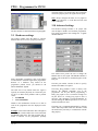
If you’re used to programming your chip with another
programmer than a SCHAER type one, then it is
possible to customize the position of these signals in
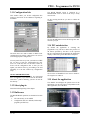
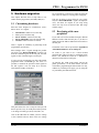
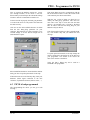
the LPT registers. You can easily do it from the
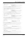
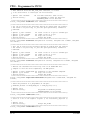
ADVANCED window of the DLL:
are not possible on a LPT port (2 signals are using the
same value for instance), a message box will appear.
Take care to choose a correct value for every signal.
Only the “DATA FROM PIC” signal is an input (PC
view), the others are outputs. If you setup wrong
values, the chip won’t be detected (the ZIF image
remains empty).
5.2 Developing with a new
peripheral
If you want to access the hardware through a different
hardware interface than the LPT port, so you have to
modify both of the Macros dedicated to the transfer to
the LPT port.
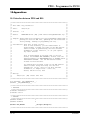
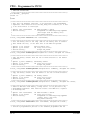
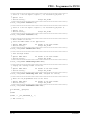
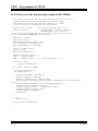
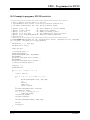
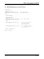
The details of the code are presented in Appendix D
“MACRO definitions to access LPT port”.
Of course if you want to use a block oriented
peripheral like USB you’ll have to rebuild the entire
Driver.c file. Indeed the actual file is dedicated to
character-oriented device (LPT port)…
An interface like USB would greatly increase the
global performance of the data transfer and also
would allow programming the PIC18 under 5V only,
without any external power supply, just by using the
5V provided by the USB connection.
This panel allows the user to setup the LPT port, but
doesn’t provide a way to modify the transfer protocol
or to change of COM type (serial, USB, fibre, etc).
Click on the OK button to validate your new settings
or the CANCEL button to abort. If the new settings
13 / 27
10/23/2003