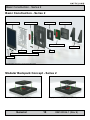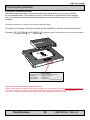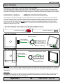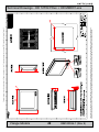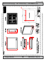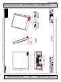
1
USER MANUAL Series 2 - Displays and Backpack range HD 12T04 xxxx - 12.1 inch Display HD 15T06 xxxx - 15.0 inch Display HD 19T03 xxxx - 19.0 inch Display HD MMD01 xxx - Maritime Multi Display Backpack User Manual MMD Series 2 Updated: 22 Nov 2007 Doc Id: INB100026-1 (Rev 9) For models: BOAA, BOBA, FOAA, FOBA, COAA, COBA (standard models) BOAC, BOBC, FOAC, FOBC, COAC, COBC (with touch screen) MMD01-Ax1, MMD01-Ax2 (AC and DC) MMD01-Cx1, MMD01-Cx2 (AC and DC + touch support) Please visit our website for the latest electronic version of this manual. Hatteland Display AS, Åmsosen, N-5578 Nedre Vats, Norway Tel: (+47) 5276 3700 - Fax: (+47) 5276 5444 - e-mail: [email protected] Copyright © 2007 Hatteland Display AS Aamsosen, N-5578 Nedre Vats, Norway Information in this manual is copyrighted to the respective owners. All rights are reserved by Hatteland Display AS. This information may not, in whole or in part, be copied, photocopied, reproduced, translated or reduced to any electronic medium or machine-readable form without the prior written consent of Hatteland Display AS. The products described, or referenced, herein are copyrighted to the respective owners. The products may not be copied or duplicated in any way. This documentation contains proprietary information that is not to be disclosed to persons outside the user’s company without prior written consent of Hatteland Display AS. The copyright notice appearing above is included to provide statutory protection in the event of unauthorized or unintentional public disclosure. All other product names or trademarks are properties of their respective owners ! WARNING: This is a class A product. In a domestic environment this product may cause radio interference in which case the user may be required to take adequate measures. Contents Contents..................................................................................... 3 Contents of package...........................................................................6 General....................................................................................... 7 Introduction to Hatteland Display AS................................................... 8 About this manual................................................................................9 Basic Construction - Series 2............................................................ 10 Product Labels (Examples)............................................................... 11 Serial Number Labels Placement.................................................. 11 Warranty Label.............................................................................. 11 Windows® OEM Certificate of Authenticity (COA)........................ 11 Serial Number Label Layout (Display Module)..............................12 Serial Number Label Layout (Backpack Module)..........................12 Touchscreen products.......................................................................13 Location of Touchscreen label.......................................................14 Installation................................................................................ 15 Installation and mounting..................................................................16 Panel cut-out mounting precaution.................................................... 17 Ergonomics.......................................................................................17 Cables...............................................................................................19 Cable Entries & Connectors (Marked area) - Illustration only.......19 Backpack / Bracket Replace / Removal - Series 2............................ 20 Operation.................................................................................. 23 User Controls....................................................................................24 Status LED Overview........................................................................25 For ECDIS Calibrated Products........................................................ 25 On Screen Display (OSD) Menu Navigating..................................... 26 On Screen Display (OSD) Menu Overview....................................... 27 On Screen Display (OSD) Menu Functions....................................... 29 Physical Connections - MMD Backpack Series 2............................. 34 IND100130-16 IND100130-18 INB100026-1 (Rev 9) Contents Specifications.......................................................................... 37 Specifications - HD 12T04 BOxx + HD MMD01-xxx......................... 38 Specifications - HD 12T04 FOxx + HD MMD01-xxx......................... 39 Specifications - HD 12T04 COxx + HD MMD01-xxx......................... 40 Specifications - HD 15T06 BOxx + HD MMD01-xxx......................... 41 Specifications - HD 15T06 FOxx + HD MMD01-xxx......................... 42 Specifications - HD 15T06 COxx + HD MMD01-xxx......................... 43 Specifications - HD 19T03 BOxx + HD MMD01-xxx......................... 44 Specifications - HD 19T03 FOxx + HD MMD01-xxx......................... 45 Specifications - HD 19T03 COxx + HD MMD01-xxx......................... 46 Technical Drawings................................................................. 47 Technical Drawings - HD 12T04 BOxx + HD MMD01-xxx................ 48 Technical Drawings - HD 12T04 FOxx + HD MMD01-xxx................. 49 Technical Drawings - HD 12T04 COxx + HD MMD01-xxx................ 51 Technical Drawings - HD 15T06 BOxx + HD MMD01-xxx................ 52 Technical Drawings - HD 15T06 FOxx + HD MMD01-xxx................. 53 Technical Drawings - HD 15T06 COxx + HD MMD01-xxx................ 55 Technical Drawings - HD 19T03 BOxx + HD MMD01-xxx................ 56 Technical Drawings - HD 19T03 FOxx + HD MMD01-xxx................. 58 Technical Drawings - HD 19T03 COxx + HD MMD01-xxx................ 60 Accessories............................................................................. 61 Technical Drawings - HD xxVESA TBR-A1....................................... 62 Technical Drawings - HD xxTBR CMB-A1......................................... 63 Specifications - Serial Split Cable..................................................... 65 IND100130-16 IND100130-18 INB100026-1 (Rev 9) Contents Appendixes.............................................................................. 67 Pin Assignments - Common Connectors........................................... 68 Preset Signal Timings........................................................................70 Basic Trouble-shooting......................................................................72 Declaration of Conformity..................................................................73 Return Of Goods Information............................................................ 74 Terms.................................................................................................75 Pixel Defect Policy.............................................................................77 Notes.................................................................................................78 Display Firmware Version ............................................................78 Safety Considerations...................................................................78 Revision History................................................................................80 Contact Information................................................................ 82 IND100130-16 IND100130-18 INB100026-1 (Rev 9) Contents of package This product is shipped with: Item Description Illustration 1 pcs of Standard DVI Signal Cable. DVI-D 24P Male to DVI-D 24P Male - Length 1.8m 1 pcs of Standard VGA Signal Cable DSUB 15P Male to DSUB 15P Male - Length 1.8m 1 pcs of Standard Power Cable . (European Type F “Schuko” or US Type B standard plug) Length 1.5m Note: Power cable(s) not included in the DC version. 1 pcs of DVI-I > RGB/VGA adapter DVI-I 24P Male to DSUB 15P Female 1 pcs of User Manual 1 pcs of Series 2 Bracket stand. Note: Only supplied with the Bracket version of the complete unit (display unit + backpack unit). This bracket is factory premounted. Optional Contents of Package: Item Description Illustration 1 pcs of Standard USB Cable TYPE B to TYPE A - Length approx: 1.5m Note: This cable is only included if you purchased a product with factory mounted touchscreen. IND100131-11 INB100026-1 (Rev 9) General INB100026-1 (Rev 9) Hatteland Display AS Introduction to Hatteland Display AS Founded in 1987, Hatteland Display offers the widest range of type approved marine monitors, panel computers and type approved marine computers for the worldwide commercial, naval, yacht and cruise market. Today the group develops and manufactures a complete range of IEC 60945 tested marine monitors, panel computers and IEC 60945 tested marine computers. “Design meets Functionality” - Series 2 ATTRACTION is more then just to show a nice picture on a screen. The new IEC60945 tested man-machine interfaces, offered by Hatteland Display AS, will fulfill the customers wish for outstanding design combined with the reliability of approved maritime Panel-Computers and Displays. These IP rated products are meant to be usable in all maritime applications. By the proven optical bonding technology, the Panel Computers and Displays show drastically reduced reflection and enhanced optical performance. This truly allows inside or outside use of these products. Cool is not only the design, but also the product by intelligent heat dissipation and reduced heating storage. Using state-of-the-art components such as LCD-TFT Modules and ETX-PC bases industrial computers, long-term availability and serviceability is secured. Flexibility in application and service friendliness is achieved by a unique backpack solution, whereas the detachable backpack contains the “intelligence” of the product. The extreme small form factor used on this product line with a general depth of only 75mm (!) and for example for the 19in with 416 (W) x 372 (H) mm, allows new-builds and retrofit installation almost everywhere. The flush mounted glass front shows only what is necessary: the content of the picture. The frameless design can smoothly be integrated into a console or it can be used as table mounted device (bracket version). A console version are also available for installment on flybridges with IP66 rating. This new HATTELAND® Series 2 Panel Computers MMC2 and Displays MMD2 will be available from Q2 2006 onwards in 12in., 15in. and 19in. sizes. The concept allows easy scaling in sizes from small LCD screens up to large sizes of more than 32in LCD wide-screens. This outstanding and affordable product range offers a wide choice for different needs. Optical Technology With the Optical Bonding technology - where the space between the front glass and the TFT module is filled with a special substance, the bonded products offers the best sunlight viewing of any marine displays today. Sunlight reflection has been drastically reduced and the inclusion of a 0-100% backlight ensures the screen can be viewed with excellent clarity, day or night. The bonding process also has another benefits; with no space for heat and moisture to collect in the display, and also they does not suffer from condensation, also known as misting. Approved Marine Displays (MMD/STD) - Series 1 Hatteland Display’s marine monitors are based on high quality and state-of-the-art components with the highest specifications, and meet all requirements for harsh maritime use. The displays are easily integrated into your system, due to standardized products and features. The MMD (Maritime Multi Display) series consists of sizes ranging from 10in to 23in. Specifically designed for navigation and automation systems on ships, these certified LCD monitors comply to IP66 described in IEC 60925, are tested according to IEC 60945 and are approved by major classification societies such as ABS, BV, ClassNK, DNV, GL and LR. Further to this marine standard, the 19in MMD, the 20in MMD and the 23in MMD marine monitors are also available as ECDIS and ARPA radar-compliant units. General IND100077-1 INB100026-1 (Rev 9) Hatteland Display AS Approved Marine Panel Computers (MMC) - Series 1 The combination of the reliable design of the marine TFT-LCD modules, together with industrial computer boards, allows Hatteland Display to offer a product range for customer applications where space is critical and full function is desired in a single unit. In particular, the standardized ETX-board form factor allows full flexibility when it comes to processor choice. Because of multiple useful standard components we can offer a highly attractive commercial package The MMC (Maritime Multi Computer) series consist of sizes ranging from 10in to 23in. These products have also been designed for typical marine applications in navigation, automation and other systems. Following Hatteland’s philosophy, these marine panel computers are fully tested according to IEC 60945 and are designed for type approval. Approved stand-alone and rack-mounted marine computers Two concepts are followed to offer variation in size, function and expansion slots for customers: approved black-box computers for limited space and approved computers for standard 19in racks, which offer a high degree of expansion. Configurations according to customer wishes are implicit, such as the operating system, CD-burner, RAM, graphic card, HD, add-on cards, factory installed software and many, many more. The approved computers are tested according to IEC 60945 and IACS E10 and meet the requirements for IEC 61174 (ECDIS). Several approvals by major classification societies such as ABS, BV, ClassNK, DNV, GL and LR are available or pending. Flexible display solutions and night vision facilities All Type Approved displays, panel computers and marine computers provide maximum flexibility for customer applications. We offers all products with AC or DC power supply, and marine displays and marine panel computers have a fully linear dimmable function for night vision. Upon customer request, specific color, mechanical and electrical function designs can be implemented. Many more options are also available such as, sun visors, mounting brackets, different Windows or Linux operating systems and touch screens. All products are designed and manufactured in Nedre Vats, Norway. The production and configuration of all products takes place within Hatteland’s high capacity production plant#1 (opened in September 2003) in Nedre Vats, Norway. Hatteland’s production facilities are designed for future expansion, which has enabled the creation of plant#2, our Optical Technology facility, opened in October 2006. The chosen materials for the production of our products are high grade industrial components able to fulfil form, fit and function requests. About this manual The manual contains electrical, mechanical and input/output signal specifications. All specifications in this manual, due to manufacturing, new revisions and approvals, are subject to change without notice. However, the last update and revision of this manual are shown both on the frontpage and also in the “Revision History” chapter. Please use that as a reference. Furthermore, for third party datasheet and user manuals, please see dedicated interactive CD (where included) delivered with the product or contact our sales personnel for support. Please see the Contents Of Package chapter in the beginning of this manual to determine if a dedicated manual CD are included. General IND100077-1 INB100026-1 (Rev 9) Basic Construction - Series 2 Basic Construction - Series 2 Bonded Glass/TFT Backpack Cover Electronics / PCB’s Backpack Casing Backpack Electronics Stand Bracket Centerbox Mounting Flange* Casing User Controls (Bracket or Console Version) USB Hatch *Available with or without flange (factory default deliverance) Modular Backpack Concept - Series 2 Display and MMD2 (Display) Backpack General IND100077-39 10 Display and MMC2 (Computer) Backpack INB100026-1 (Rev 9) Product Labels (Examples) Serial Number Labels Placement The Series 2 products are based on a modular backpack concept, which allows users to easily change the functionality. Both the display modules and the backpack modules are by factory default labelled with unique labels. These are located as illustrated below. Location Display Module: Location Backpack Module: Top o f bac kpac k Top of backpack Warranty Label If you are to perform service on a unit still under warranty, any warranty will be void if this label is attempted removed / re-glued or removed completely. This label is located on the product as shown in illustration. Underside backpack Windows® OEM Certificate of Authenticity (COA) Applies for products after JAN/FEB 2007. On the Series 2 MMC (computer backpack), a COA label for the operating system license is placed as shown in illustration. Windows® OEM Certificate of Authenticity (COA) Top o f bac kpac k Top of backpack Applies for products produced before FEB 2007. On the Series 2 MMC (computer backpack), a COA label for the operating system license is placed as shown in illustration. Underside backpack General IND100077-40 11 INB100026-1 (Rev 9) Product Labels (Example) Serial Number Label Layout (Display Module) Manufacturer & Country Description Product Type Manufacturer HATTELAND DISPLAY AS - NORWAY Product 19 Inch TFT - Series 2 Product type HD 19T03 BOAA SERIAL NUMBER HD 19T03 BOAA-0000120 Serial Number Barcode (TYP+SNO) Code 128 Barcode ID Serial Number Label Nomenclature (TFT Module) HD yyxyy xxxx-yyyyyyy NOMENCLATURE (y=Numbers, x=Letters) HD 19T03 BOAA-0000120 Example Serial Number ID Factory Mounted Option ID (A=STD, C=Touch Screen) User Interface Type ID (A=Std+USB, B=IP66) Glass/TFT Technology ID (O=Optically Bonded) / Reserved Customer ID Mechanical Version ID (B=Bracket & C=Console) TFT/Electronics Revision ID TFT (Thin Film Transistor) Display Size (inch) Manufacturer ID Serial Number Label Layout (Backpack Module) Product Type Description Manufacturer Product Product type Power SERIAL NUMBER Input Voltage Serial Number Manufacturer & Country Barcode ID HATTELAND DISPLAY AS - NORWAY MMD Backpack - Series 2 HD MMD01-A01 115 & 230VAC - 50/60Hz 100W HD MMD01-A01-0000120 Code 128 Barcode (TYP+SNO) Power Rating Serial Number Label Nomenclature Hx xxxyy-xyy-yyyyyyy NOMENCLATURE (y=Numbers, x=Letters) HD MMD01-A01-0000128 Example Serial Number ID Power Input ID (1=AC - 115&230VAC / 2=DC - 24VDC) Electronics / Mainboard Revision ID Sub Version ID (A=STD, C=Touch Support) / Reserved ID Processor Type+Speed / Reserved ID Backpack Technology Type (MMD/MMC) / Reserved Customer ID Manufacturer ID General IND100077-40 12 INB100026-1 (Rev 9) Touchscreen products Introduction to products with touchscreen Both Resistive and Capacitive touchscreen solutions are used for our products. Please visit our website to find your exact type number and then determine if it uses Resistive or Capacitive. If you have a customized or tailored product, please check the specifications in this manual or third-party specifications from your supplier. Capacitive Touchscreen Capacitive touchscreens operate using oscillator circuits that are located in each corner of the glass overlay and measure the capacitance of the area to be “touched”. Depending on where the user touches the overlay, the oscillators will vary in frequency. A touchscreen controller then measures the frequency variations to ascertain the coordinates of the person’s touch. This glass overlay has a coating that stores the charge deposited over its surface electrically. It will not operate with either a gloved hand or with a mechanical stylus. CAPACITIVE - Brief Specifications Subject Details Construction Top: ClearTek protective overcoat protects the sensors and increase durability. Inside: Electrode X/Y grid pattern and conductive coating. Bottom: Glass and conductive coating. Small amount of voltage is applied to the four corners for measuring X and Y coordinates of the touch point. Positional Accurancy Reported touch coordinates are within 1.0% of true position. (Based on viewing area dimensions) Touch Contact Requirements 3 ms for finger input. Enduarance Tested More than 225 million touches in one location without noticable degradation to the surface. Cleaning Water, isopropyl, alcohol, and similar non-abrasive cleaners. Liquid Resistance Liquids on screen does not impede touchscreen performance. Light Transmission Up to 88% at 550 nm; dependant on specific surface finish chosen. Resistive Touchscreen It generally uses a display overlay composed of layers, each with a conductive coating on the interior surface. Special separator “dots” are distributed evenly across the active area and separate the conductive interior layers. The pressure from using either a mechanical stylus or finger produces an internal electrical contact at the “action point” which supplies the controller with vertical and horizontal analog voltages for data input. The resistive touchscreens are anti-glare to reduce reflective shine intensity, which will slightly diffuse the light output throughout the screen. Resistive technology activation can be initiated by; a gloved hand, fingernail, mechanical stylus or an ungloved finger. RESISTIVE - Brief Specifications Subject Details Construction Top: Polyester with outside hard-surface coating with clear or anti-glare finish. Inside: Transparent conductive coating. Bottom: Glass substrate with uniform conductive coating. Top and bottom layers separated by separator dots. Positional Accurancy Standard deviation of error is less than +- 0.080-inch (2mm). Touch Activation Force Typically 57 to 133 g Expected Life Performance More than 35 million touches in one location without failure, using a stylus similar to a finger. Chemical Resistance (Exposed for one hour) Acetone, Ammonia-based glass cleaners, Common food and beverages, Hexane, Isopropyl alcohol, Methylene chloride, Methyl ethyl ketone, Mineral spirits, Turpentine Light Transmission Typically 75% over visible light spectrum. Touchscreen IND100110-1 13 INB100026-1 (Rev 9) Touchscreen products Location of Touchscreen label Information about the factory mounted touchscreen and what driver to use, are indicated on the dedicated label. The location is shown in this illustration together with label example. We use the same touchscreen glass technology and controller technology on all the Series 2 products. (This label is attached on products produced after September 2006) If this label is not present, the type numbers can be identified to indicate mounted touchscreen. Example: HD 19T03 BOAC & HD MMD01-C01 (Underlined and in bold indicates C as touchscreen models) || Displaymodule || || Backpack || n: EEN h Scree Touc 0 H SCR 65-00 TOUC a Resistive 0551 tems with hSys roller P/N 0 ped 4-221 equip : ELO Touc l Cont ct is Seria om VSD10056 produ : 2210.elotouch.c rer This factu : www Manu Controller h Touc Download r Drive TOUCH SCREEN This product is equipped with a Resistive Touch Screen: Manufacturer : Hampshire Company Touch Controller : TSHARC-12V Driver Download : www.tsharc.com VSD100564-TSHARC-12V Actual label on Series 2 products Up-2-date touchscreen drivers and documentation: Please visit the 3rd party website as indicated on the label. You can also visit our website www.hatteland-display.com to view the full list of our models with touchscreen. Before using the touchscreen, it should be calibrated for your system. Please install the 3rd party software and use the Calibrate function from there. Touchscreen IND100110-4 14 INB100026-1 (Rev 9) Installation 15 INB100026-1 (Rev 9) General Installation Recommendations Installation and mounting 1. Most of our units are intended for various methods of installation or mounting (panel mounting, bracket mounting, ceiling/wall mounting etc.); for details, please see the relevant mechanical drawings. 2. Adequate ventilation is a necessary prerequisite for the life of the unit. The ventilation apertures (red/gray area shown in the illustration to the right) must definitely be kept clear. The Series 2 units was designed to be fan less, and covering up the ventilation apertures (shown in closeup chassis below) is not permissable, doing so can lead to overheating and could damage the unit. Suggested and a safe minimum air distance between the ventilation apertures and other panels near the unit should be 5cm. However, this can be lower or higher depending on the installation space and design. If in question, please contact your local installation technican or qualified personnell for advise! 3. Generally, do not install the unit in a horizontal position (laying down), as this will cause heat to build up inside the display which will damage the LCD Panel. To prevent this problem we recommend installing the unit in a vertical position (±40 degrees) to improve the airflow through the unit. 4. To further improve the cooling of the unit we recommend installing Cooling Fans underneath blowing upwards going past the ventilation apertures. This may be required in high temperature applications and also when there is reason to expect temperature problems due to non-optimal way of mounting. 5. Exposure to extreme direct sunlight condition over longer periods can cause a considerable increase in the temperature of the unit, and might under certain circumstances lead to overtemperature. This point should already be taken into consideration when the bridge equipment is being planned (sun shades, distance from the windows, ventilation, etc.) 6. Space necessary for ventilation, for cable inlets, for the operating procedures and for maintenance, must be provided. 7. Information about necessary pull-relievers for cables is given in the installation drawings. Attention must be paid to this information so that cable breaks will not occur, e.g. during service work. 8. Do not paint the product. The surface treatment influences on the excess heat transfer. Painting, labels or other surface treatments that differ from the factory default, might cause overheating. Installation IND100078-12 16 INB100026-1 (Rev 9) General Installation Recommendations Panel cut-out mounting precaution If you intend to mount the bracket / stand-alone product into a precut panel, make sure you have read and understood the following section. The Series 2 frameless design means that the front glass reaches all the way to the outer rims of the product. Further, between the product chassis and the backside of the glass there is a small gap which is fi lled with a gasket. This little gap is subject of beeing “hooked” into the cut-out area edge if it is really tight and you mount the product hasty. Also, if your panel cut-out have small deviations you can accidentally break the glass edges. Try to slide the product gently straight forward and avoid skewing the product. Do not force the product into place. If you find yourself in this position and notice that the back of the glass edge is forced forward by the panel cut-out edges or you suspect a pressure building up, remove the product, carefully modify the panel cut-out and check the dimensions again. The product can not be adjusted / modified in any way. The modifcation/adjustment has to be performed on the cut-out. 1: Start sliding the product into the cut-out area 2: Continue to slide, while checking the corners 3: Glass edge now aligned. Fasten the product. Ergonomics 1. The product glass is covered by a clear protective plastic film. After installation & mounting is completed, remove this film by lifting it at a corner, and slowly pealing it off the glass. The front surface of the display glass has an anti-reflective (AR) coating which can be scratched and damaged with improper cleaning. After removing the protective film the glass surface will require cleaning. It is recommended to use only 90+% pure Isopropyl alcohol (Isopropanol) and a soft fabric cloth for this first cleaning. Fold a cloth into a small pad, dampen the cloth with alcohol, and wipe the glass from one edge to the other in one direction with one continuous motion. The product glass will require cleaning as needed. The soft cloth & alcohol wipe is recommended to clean fingerprints and oils off the glass. Water stains (including coffee, tea & coke) should be first cleaned off the glass with a soft fabric cloth wet with water, immediately followed with wiping using an alcohol wetted cloth. Installation IND100078-12 17 INB100026-1 (Rev 9) General Installation Recommendations 2. Adjust the unit height so that the top of the screen is at or below eye level. Your eyes should look slightly downwards when viewing the middle of the screen. 3. Adjust screen inclination to remain gaze angle to the centre of the screen approximately perpendicular to the line of gaze. 4. When products are to be operated both from a sitting position and from a standing position, a screen inclination of about 30° to 40° (from a vertical plane) has turned out to be favourable. 5. Series 2 are optically enhanced to reduce reflections and are viewable in direct sun light, but as a general rule the units at the bridge wing area is recommended to be installed or mounted by suitable alignment or bulkhead / deckhead mounting in such a way that reflections of light from the front pane of the display are not directed into the observer’s viewing direction. 6. The use of ordinary commercial filter plates or filter films is not permitted for items of equipment that require approval (by optical effects, “aids” of that kind can suppress small radar targets). General mounting instructions - The useful life of the components of all Electronics Units generally decreases with increasing ambient temperature; it is therefore advisable to install such units in air-conditioned rooms. If there are no such facilities these rooms must at least be dry, adequately ventilated and kept at a suitable temperature. - With most Electronic Units, cooling takes place via the surface of the casing. - In the area of the wheel house, the distance of each electronics unit from the magnetic standard compass or the magnetic steering compass must not be less than the permitted magnetic protection distance. This distance is measured from the centre of the magnetic system of the compass to the nearest point on the corresponding unit concerned. - Units which are to be used on the bridge wing must be installed inside the “wing control console” protected against the weather. In order to avoid misting of the viewing screen, a 25 ... 50 W console-heating (power depending on the volume) is recommended. - When selecting the site of a display unit, the maximum cable lengths have to be considered. - Transportation damage, even if apparently insignificant at first glance, must immediately be examined and be reported to the freight carrier. The moment of setting-to-work of the equipment is too late, not only for reporting the damage but also for the supply of replacements. Installation IND100078-12 18 INB100026-1 (Rev 9) General Installation Recommendations Cables Use only high quality shielded signal cables for RGB / DVI signals. Cable Entries & Connectors (Marked area) - Illustration only Bottom View Back View Maximum Cable Length The signal cables should generally be kept as short as possible to provide a high quality output on the display. The maximum cable length will depend on the signal resolution and frequency, but also on the quality of the signal output from the computer. Recommended refresh rate is 60Hz. Cables up to 10 meters generally provides good picture quality even with a 1600x1200 (UXGA) 60Hz signal. In most cases (especially with lower resolutions) even longer cables will provide a satisfactory result. This should however be tested in advance before making the decision on how far the unit can be placed from the signal source. Installation IND100078-12 19 INB100026-1 (Rev 9) Backpack / Bracket Replace / Removal - Series 2 How to change functionality / replace backpacks or remove bracket from product. The Series 2 products are based on a modular backpack concept, which allows users to easily change the functionality. To change the functionality of your product from a display product to operate as a computer product or vice versa for example, please follow this procedure. Note: Please review the corresponding manual for your backpack on how to operate your Series 2 product. Also review the serial number label on the backpack. These labels have information regarding the power input. Note: Ignoring the warnings we have provided with the icon, will be subject for warranty void. 1: Turn the power off and remove all cables. Place the product as indicated on a table. Make sure the display glass is protected! The navigator control should be free of any obstruction. Do not move the product on the table while its in this position, as this will scratch and damage the glass. 12mm 2: With bracket: Remove all 8 screws as shown. Note: On 12inch there is only 4 screws (4x12mm) (DIN 965 Torx A4 Black) located on the product. Length: 12mm 10mm 6mm Length: 10mm Do NOT mount/dismount the bracket/backpack when the product is in a upright/stand position. Place it as shown in step 1 above. Length: 12mm Notice where the different lengths of screws are located. Failure to remount the screws back to their original factory location may cause the bracket to loose it’s strength and/or stability. Bracket Removal If you wish to use the Series 2 product without the factory mounted bracket, remove all 8 screws (4x10mm and 4x12mm) (DIN 965 Torx A4 Black) as shown in step 2 above. Now, leave the backpack in place and fasten it to the display module using 4x6mm screws as shown in illustration (step 3) below. DO NOT EXCEED THE LENGTH OF 4x6mm WHEN MOUNTING/REMOUNTING THE BACKPACK TO THE DISPLAY MODULE. 3: Without bracket: Remove 4 screws only. 4x6mm. Installation IND100078-13 Length: 6mm 20 Length: 6mm INB100026-1 (Rev 9) Backpack / Bracket Replace / Removal - Series 2 4: Lift the backpack gently with both hands upwards from the display module. Now change backpack and repeat steps 3-2 above in reverse. Again note the length of the screws and their locations as shown in the previous steps. 5: Note serial numbers of backpack AND the main display module. The serial numbers are located on the labels. Like: HD MMD01-A01-0000128 (Backpack) HD 19T03 BOAA-0000120 (Display module) 6: The HATTELAND® Series 2 products are shipped mounted and fully operational with a customized combination of display unit and backpack unit. The two serial numbers are linked and registered by Hatteland, and together constitute an important basis for future customer service, quality records and technology improvements. IMPORTANT: Hatteland Display provides normal warranty after any changes of backpack / display module combinations, when changes are made according to this manual AND when information of serial numbers after such changes are reported back to the Hatteland Display service department. The following information should be returned to Hatteland Display AS, attn: Service Department: - Customer / end-user name and address - Date of change - Serialnumber of display module. - Serialnumber of backpack module. fax e-mail - Serialnumber of replaced module (display or backpack). phone If several units are reported, note which units are mounted together. 7: For the MMD backpacks you must SETUP DDC (Display Data Channel) to reset/optimize image information. It allows the display to send its specifications to the display controller. For more information on how to use the On Screen Display (OSD) menu, please review the “OPERATION” chapter in this manual first. Reconnect power to the product and turn it on. Enter the OSD menu and navigate your way through the “Utilities / Load Default “ submenu. (FIG 1) FIG 1 Utilities User Setting OSD Setting Zoom Calibrate RGB Gain Display Orientation Load Default Test Pattern Return Load User Default Save User Default Load Factory Default Setup DDC Return FIG 2 Navigate down to SETUP DDC and execute it. (FIG 2) A message “Press MENU to Setup DDC” will appear. Press the navigator button/knob to execute. Installation IND100078-13 21 INB100026-1 (Rev 9) This page left intentionally blank 22 INB100026-1 (Rev 9) Operation Series 2 Products 23 INB100026-1 (Rev 9) User Controls NAVIGATOR OVERVIEW - Maritime Multi Display (MMD): The products features a multi functional user control via the navigator rotary & push knob with 8 independent LEDs for multiple feedback on different status/modes that may occur during usage. With this navigator you can also control brightness and navigating the OSD menu for further preferences. Two different versions are available of this navigator: Bracket Version (i.e. cockpit use) Console Version (i.e. flybridge use) = 1-button (with rotary switch and USB Connector) = 3-button (without rotary switch and USB Connector) The navigator is mounted into the glass by factory default and can not be replaced afterwards. The console version of the user controls in front is IP66 rated. Please refer to the illustrations below to determine what version you have and how to operate the unit. The USB connector is located behind the HATTELAND® rubber hatch in the right lower corner in the front. The rubber hatch IS NOT designed to be removed, but lifted/bended away as the arrow below shows. Use a pen, nail or similar to open the hatch. The rubber hatch can later be pushed back into place when the USB front connector is not in use. 1-BUTTON VERSION WITH FRONT USB BEHIND RUBBER HATCH: Rubber hatch lifted away -> With rubber hatch in place -> 1-BUTTON VERSION: Rotary Function Push Function +HOT KEY function Status LED Ring 3-BUTTON VERSION: Decrease/Increase Push Function Push Function +HOT KEY function Status LED Ring Power ON: To turn the unit on, push the navigator knob/button inwards. The unit will start searching for signal sources. A green led will move around the led ring. Please read the STATUS LED overview on the next page for verification on the various LED patterns. Power OFF: To turn the unit off, push the navigator knob/button inwards and hold it down for 6 seconds, after 3 seconds the menu will appear. 3 seconds later the unit is turned off, and all LED indicators will turn red. Also read the STATUS LED overview on the next page for various LED patterns. Operation IND100064-13 24 INB100026-1 (Rev 9) Status LED Overview HOT KEY FUNCTION: User can access input video/signal sources by DOUBLE clicking the navigator knob/button inwards. The cycle of the video/signal detection are; Analog RGB1, Analog RGB2, DVI, Composite Video & S-Video. It will only switch to the next detectable video/signals sources that are present (physically connected). The incoming signal will be identified and displayed as clear text in the upper left corner of the display. STATUS LED OVERVIEW The display features a multi purpose indicator LED status ring which through different patterns and realtime activity gives back the status of the signal detected, power on/off, calibration, menu activity and more. The LEDs are multicolored which either illuminate green or red, based on the activity. OFF (No power connected) OFF (Standby, power detected) ON (Signal Search) 8 LED OFF 8 RED LED STATIC ON 1 GREEN LED MOVEMENT looping. ON (Signal OK) ON (No Signal) ON (Menu Delay) 8 GREEN LED STATIC ON 4 RED LED STATIC ON 7 GREEN LED STATIC + 1 LED OFF MOVEMENT doing 1 loop. OFF (Shutdown) 1 RED LED MOVEMENT doing 1 loop. For ECDIS Calibrated Products For the MMD/MMC products that are ECDIS calibrated from factory, the following LED pattern (Calibrated) indicates that the backlight/brightness is at calibrated level. (Calibrated +) or (Calibrated -) means that the knob/brightness is above or below the calibrated brightness level. Fine adjust the navigator knob either clockwise or counter-clockwise until the pattern for (Calibrated) is reached. ON (Calibrated) ON (Calibrated +) ON (Calibrated -) 4 GREEN LED STATIC ON 4 GREEN LED STATIC ON + where 1 show BRIGHTNESS INDICATION POSITION 4 GREEN LED STATIC ON + where 1 show BRIGHTNESS INDICATION POSITION Operation IND100064-13 25 INB100026-1 (Rev 9) On Screen Display (OSD) Menu Navigating QUICK START: The On Screen Display (OSD menu) is accessible by pushing the navigator knob/button inwards AND hold it for 3 seconds. To understand the menu and its usage, please follow these steps for a quick start. 1-BUTTON VERSION: (with rotary switch and USB Connector) 1: While powered on, and image visible on screen, push the navigator knob inwards and hold for 3 seconds. The OSD menu will be visible with available functions you can adjust or control. 2: You can move to the next function icon by using the navigator rotary function (clockwise or counter-clockwise) Select function by pressing the navigator knob inwards. You will now enter it’s menu and options. 3: Select clear text options within icon menu by using the navigator rotary function again. It will be possible to navigate upwards and downwards by rotating the navigator knob. The selected option will turn yellow. Push the navigator knob inwards once and the option will be editable. 4: Use the navigator rotary function to increase/decrease/select values or enter sub-menus. 5: To confirm the changes, select the option “RETURN”. After this, navigate to the EXIT icon and push the navigator knob to save settings and remove the menu overlay. “RETURN” will always exit to the previous menu. 3-BUTTON VERSION: (without rotary switch and USB Connector) 1: While powered on, and image visible on screen, push the navigator button inwards and hold for 3 seconds. The OSD menu will be visible with available functions you can adjust or control. 2: You can move to the next icon by pushing the decrease/increase (-/+) buttons. Select function by pressing the navigator button inwards. You will now enter it’s menu and options. 3: Select clear text options within icon menu by pushing the navigator button. It will be possible to navigate upwards and downwards by pushing the decrease/increase (-/+) buttons. The selected option will turn yellow. Push the navigator button inwards once and the option will be editable. 4: Use “-” or “+” buttons to increase/decrease values or enter sub-menus. 5: To confirm the changes, select the option “RETURN”. After this, navigate to the EXIT icon and push the navigator knob to save settings and remove the menu overlay. “RETURN” will always exit to the previous menu. OSD MENUS: The OSD menu consists of 4 modes: (This icon will indicate if function is available throughout the manual). 1 3 Mode 1 - Available functions in RGB / DVI MODE “Simplified” OSD Menu - (Logo will appear) User can adjust the most common functions needed to operate the display. *Some functions are not available in DVI mode Mode 2 - Available functions in RGB / DVI* MODE “Full” OSD Menu - (No logo will appear) User can access more advanced functions. (Service menu) *Some functions are not available in DVI mode Mode 3 - Available functions in VIDEO MODE “Simplified” OSD Menu - (Logo will appear) User can adjust the most common functions needed to operate the display. 2 Mode 4 - Available functions in VIDEO MODE “Full” OSD Menu - (No logo will appear) User can access more advanced functions. (Service menu) 4 RGB/DVI MODE = When RGB/DVI signal (i.e OS or radar / charts) are displayed full screen. VIDEO MODE = When video signal (i.e CAMERA / VCR / DVD) are displayed full screen. OSD KEYCODE/MODES: If the OSD menu has been set to “Simplified” mode, a special keycode has to be entered before the OSD menu will be accessible as “Full” mode again. After changes has been made in the “Full” mode, and user exits the menu, the OSD menu will reset back to “Simplified” upon next entry of the OSD Menu. This can be overridden while in “Full” mode, by setting the “Utilities/OSD Settings/Default OSD Mode/” to always be in “Full” mode. When user enters the menu anytime, the “Full” mode menu will be available always. By Factory Default the OSD menu layout is set to “Full” mode. The keycode procedure is to prevent unqualified personnel entering the OSD menu and make severe changes that may affect the overall performance of the unit after installment. The special keycode is by factory default set to 158. The keycode field will be located in the lower right corner of the screen, and looks like this: (Use the navigator buttons/knob to change/enter the code). 0 0 0 WARNING !! MODIFYING CERTAIN PARAMETERS MAY AFFECT THE PERFORMANCE OF THE DISPLAY. Operation IND100064-15 26 INB100026-1 (Rev 9) On Screen Display (OSD) Menu Overview Mode 1 - Function layout in RGB / DVI MODE “Simplified” OSD Menu: 1 Note that to be in RGB / DVI MODE, a computer signal must be present in full screen, i.e Windows or other operating system/radar system. Having a Picture-In-Picture (PIP) view simultaneously will not interfere or change the menu structure in any way. Frequency and Phase Frequency Phase Sharpness Picture Type Auto Setup Return Mode 2 - Function layout in RGB / DVI MODE “Full” OSD Menu: 2 Note that to be in RGB / DVI MODE, a computer signal must be present in full screen, i.e Windows or other operating system/radar system. Having a Picture-In-Picture (PIP) view simultaneously will not interfere or change the menu structure in any way. Brightness and Contrast Brightness Contrast Return Operation IND100064-14 27 INB100026-1 (Rev 9) On Screen Display (OSD) Menu Overview Mode 3 - Function layout in VIDEO MODE “Simplified” OSD Menu: Note: To access this menu, a video signal must be present in full screen, i.e from a camera, VCR or DVD player. 3 Video Adjustment Color Tint Sharpness Picture Type Video Type Return Mode 4 - Function layout in VIDEO MODE “Full” OSD Menu: Note: To access this menu, a video signal must be present in full screen, i.e from a camera, VCR or DVD player. 4 Brightness and Contrast Brightness Contrast Return Operation IND100064-14 28 INB100026-1 (Rev 9) On Screen Display (OSD) Menu Functions 2 4 BRIGHTNESS AND CONTRAST: (No function for DVI signals) Selecting this function will enable the user to adjust brightness and contrast for the display. (No Function in DVI) BRIGHTNESS: (No Function in DVI) CONTRAST: Increase/decrease brightness level, total: 100 steps Increase/decrease contrast level, total: 100 steps COLOR TEMPERATURE: Selecting this function will enable the user to modify the warmness of the picture. Higher temperature = “cooler” picture. Lower temperature = “warmer” picture. User can select between presets 9500K, 8000K, 6500K, and 5000K color temperature measured in Kelvin. User can also manually adjust the color temperature in R,G and B values by clicking on “Color Temperature Adjust” and enter its sub-menu. 1 2 FREQUENCY AND PHASE: (Some functions not available in DVI mode) Selecting this function will enable the user to modify the image horizontal size and fine tune the image quality. 2 4 (No Function in DVI) FREQUENCY: (No Function in DVI) PHASE: (No Function in DVI) SHARPNESS: PICTURE TYPE: AUTO SETUP: Increase/decrease the image horizontal size. Fine tune the data sampling position (adjust image quality.) Increase/decrease video image sharpness level. Motion / Still (Adjustment for best image quality) If graphics on screen move a lot, select “Motion” If graphics on screen are mostly still, select “Still” Use this to automatically adjust/fine tune/sync the incoming signal to automatic default and optimal values gathered from the graphics controller and the incoming signal. 3 4 VIDEO ADJUSTMENT: Selecting this function will enable the user to modify the color saturation of the video signal along with tint and sharpness. COLOR: TINT: SHARPNESS: PICTURE TYPE: VIDEO TYPE: Increase/decrease video color level. Increase/decrease tint level. Increase/decrease video image sharpness level. Motion / Still / Normal (Adjustment for best image quality) If graphics on screen move a lot, select “Motion” If graphics on screen are mostly still, select “Still” General motion - non flicker mode, select “Normal” Change to best match the source signal. (DVD / VCR) VIDEO SYSTEM: Selecting this function will enable the user to select video system and input signals. 3 4 AUTO : Automatic detection of NTSC or PAL system. (Not applicable in SECAM) NTSC / NTSC 4.43 : Manual select NTSC system. PAL / PAL M : Manual select PAL system. SECAM : Manual select SECAM system. Operation IND100064-14 29 INB100026-1 (Rev 9) On Screen Display (OSD) Menu Functions 1 2 STATUS: Selecting this function will display graphic information such as the detected incoming resolution and frequency. 1 2 3 4 POSITION: (No function in DVI mode) Selecting this function will enable the user to position the image within the display area. (No Function in DVI) HORZ POSITION (No Function in DVI) VERT POSITION : Position the image vertically. : Position the image horizontally. 1 2 PICTURE IN PICTURE: Selecting this function will enable the user to configure PIP window size, input signal source, horizontal and vertical position and more. PIP SIZE PIP SOURCE : Select PIP window size. Adjustable in steps 0 (off) to 24. : Select video source to be displayed in PIP window. Available sources are: AUTO = automatic detection of Composite, S-Video. COMP = manual select composite video signal only. SVID = manual select S-Video signal only. HORZ POSITION: VERT POSITION: Adjust the position of the PIP window horizontally. Adjust the position of the PIP window vertically. ADVANCED SETTINGS: (Click to enter sub-menu) - NOTE: Tint adjust not available for S-Video signals. BRIGHTNESS: CONTRAST: SHARPNESS: TINT: COLOR: ROTATION: Selecting this function will enable the user to rotate the image to either landscape (NORMAL) or portrait (ROTATED) format. 3 4 Operation IND100064-14 Increase/decrease the image brightness of the PIP window. Increase/decrease the image contrast of the PIP window. Increase/decrease the image sharpness of the PIP window. Increase/decrease the tint of the image of the PIP window. Increase/decrease the color of the image of the PIP window. 30 INB100026-1 (Rev 9) On Screen Display (OSD) Menu Functions GRAPHIC SCALING MODES: Selecting this function will enable the user to configure the graphic scaling of the RGB/DVI or VIDEO image. The change will happen realtime. 2 3 4 Note: Some of these functions will impact on image quality, and will therefore not show the optimal 1:1 picture with correct aspect ratio and resolution suitable for the TFT module. Scaling methods in PC/DVI MODE: 2 ONE TO ONE, FILL SCREEN, FILL TO ASPECT RATIO, NONLINEAR SCALING MODES Scaling methods in VIDEO MODE: NORMAL, LETTERBOX, LETTERBOX WITH SUBTITLES, NONLINEAR SCALING MODES 3 4 SCREEN 2 FILL FILL TO ASPECT RATIO : Enable full screen expansion for lower resolution image. : Enable full screen expansion for lower resolution image according to aspect ratio. LETTERBOX : Stretches a letterboxed picture to full screen. LETTERBOX WITH SUBTITLES : Stretches and pans a letterboxed picture to full screen, which enables viewing of subtitles in bottom. 3 4 2 3 4 NONLINEAR SCALING PARAMETERS: (Click to enter sub-menu) Will either clip the image off (to black), or stretch/scale the image . This will impact on image quality, and will therefore not show the optimal 1:1 picture with correct aspect ratio and resolution suitable for the TFT module. HORIZONTAL CLIPPING: HORIZONTAL OFFSET: HORIZONTAL STRETCH: VERTICAL CLIPPING: VERTICAL OFFSET: VERTICAL STRETCH: 1 LANGUAGE: Available languages are: English, Norwegian, Chinese (Simplified) and French. This will affect all text and messages in the OSD menus instantly upon selecting them. 2 3 4 Operation IND100064-14 31 Increase/decrease the horizontal clipping. Increase/decrease the horizontal offset. Increase/decrease the horizontal stretch. Increase/decrease the vertical clipping. Increase/decrease the vertical offset. Increase/decrease the vertical stretch. INB100026-1 (Rev 9) On Screen Display (OSD) Menu Functions UTILITIES: Selecting this function will enable the user to configure the OSD menu behaviour, image properties, verify BIOS Firmware version and miscellaneous operations. 1 2 3 4 2 USER SETTING: (Click to enter sub-menu) 4 DPMS : Disable / Enable the DPMS (power saving when no signal) DISPLAY INPUT : Disable / Enable displaying signal source name as OSD text. AUTO SOURCE SELECT : Off = Disable auto source select function. Low = Auto source select enabled ONLY in power up. High = Auto source select ALWAYS enabled. (Default Setting) GAMMA : 1.0 / 1.6 / 2.2 - Adjusts gamma on TFT display. DVI CABLE LENGTH : Normal / Long (By selecting “Long”, a electronic eq circuit will enhance the signal to achive longer carrier over 2m and still keep the quality/strength). COMMUNICATION SETTINGS : Serial Mode = [RS232] - [4 Wire RS485/422] - [2 Wire RS485] Serial Adress = Select and unique adress from 0 to 15 (Consult the “Serial Control Interface - MMD / MMC” manual.) 1 2 OSD SETTINGS: (Click to enter sub-menu) 3 4 OSD H-POSITION: OSD BACKGROUND OSD ROTATE USER TIME OUT DEFAULT OSD MODE FULL MENU 2 Position the OSD menu horizontally. Position the OSD menu vertically. OSD V-POSITION: : Choose between Translucent or Opaque. : Choose between Normal / Rotate. Will position the menu either horizontally or vertically. : Adjust the OSD menu time out period in a step of 5 seconds. : Simplified or Full menus. (option only available in “full mode”) : Upon selecting this function, the menu software will request a keycode to unlock the FULL menu (while in simplified mode) (Please refer to the beginning of this chapter for information) ZOOM: (Click to enter sub-menu) 4 ZOOM LEVEL: HORIZONTAL PAN: VERTICAL PAN: Zooms in the display area from center. Pan the display area horizontally. Pan the display area vertically. 1 2 CALIBRATE RGB GAIN DISPLAY ORIENTATION: (Click to enter sub-menu) Will flip/inverse the display area including PIP view. Choices are: Normal / Horizontal Inverse / Vertical Inverse / Inverse 2 4 Operation IND100064-14 : Perform automatic color calibration. 32 INB100026-1 (Rev 9) On Screen Display (OSD) Menu Functions 1 2 LOAD DEFAULT: (Click to enter sub-menu) 3 4 LOAD USER DEFAULT SAVE USER DEFAULT LOAD FACTORY DEFAULT SETUP DDC TEST PATTERN 1 2 3 4 : Load your own custom settings. : Save your own custom settings. : Will reset the VGA controller settings to the factory preset. Use caution when using this function, as this will override your current settings. : Display Data Channel. Reset/optimize image information. This function should be executed to setup correct DDC (Display Data Channel) information when the backpack has been replaced. It allows the display to send its specifications to the display controller. : Shows a generic test pattern. 1 2 3 4 VIDEO SOURCE: Selecting this function will enable the user to select the type of input signal to show fullscreen. Available inputs are: Analog RGB1, Analog RGB2, DVI, Composite Video, and S-Video. The display unit will switch signal source instantly, so if no signal source is present (physically connected) the image will be black for 1-2 seconds before it resets back to the previous detected signal. 1 2 3 4 POWER OFF: Selecting this function will start the shutdown procedure for the unit. Please read the STATUS LED overview section for more information. EXIT: Selecting this function will exit the OSD menu and save the current settings. Note: The OSD settings will also automatically be stored in memory when the OSD exit on user timeout. 1 2 3 4 Operation IND100064-14 33 INB100026-1 (Rev 9) Physical Connections - MMD Backpack Series 2 Connection area of backpack (illustration) DVI-I IN RGB IN Composite Video IN S-Video IN COM1 USB OUT COM2 Power Input Area DVI-I IN / RGB2 IN: (Supports both DVI & Analog RGB) Connect the DVI cable to the DVI-I 24+5P Connector (female) on the rear side of the TFT display. Screw the DVI cable to the connector spacers and make sure you don’t bend any of the pins inside the DVI cable connector. Connect the other end to your computer equipment. This DVI-I connector can also be converted to function as RGB IN by using the provided DVI<>RGB adapter plug. RGB1 IN: Connect the VGA cable to this D-SUB 15P Connector (female) on the rear side of the TFT display. Screw the VGA cable to the D-SUB connector spacers and make sure you don’t bend any of the pins inside the VGA cable connector. Connect the other end to your computer equipment. COMPOSITE IN (PAL/NTSC/SECAM VIDEO): S-VIDEO IN: USB OUT: Connect your composite video signal cable into this RCA jack plug. To activate the Picture In Picture function, the TFT display must be configured via the OSD menus. - Note that Composite Video must be selected as the incoming video source in the OSD menu. Connect your S-Video (SVHS) video signal cable into this mini 4-way din plug. It can only be inserted one way and make sure you don’t bend any of the pins inside your cable. To activate the Picture In Picture function, the TFT display must be configured via the OSD menus. - Note that S-Video must be selected as the incoming video source in the OSD menu. This USB TYPE B connector is used as a loopthrough from the front connector on a Series 2 TFT compatible display. It allows you to connect peripherals in the front of your display unit and connect them further to your computer equipment. The signal is transferred without any conversion and is a direct 1-1 cable connection. Operation IND100133-17 34 INB100026-1 (Rev 9) Physical Connections - MMD Backpack Series 2 COM1 SERIAL CONTROL INTERFACE: COM2 - TOUCH/FEATURE CONNECTOR: This serial remote control connector D-SUB 9PIN Female (RS232) allows to control various parameters on the TFT display such as brightness via customized software. For in-depth information, see www.hatteland-display.com: “Support/Accessories/HATTELAND® SCOM/Technical Manual” as PDF file. On Touch Screen versions of the backpack a USB Type B Connector is factory mounted here which should be connected to a computer with touch screen drivers installed. See the touch screen chapter in this manual for more information. This space/connector area is also reserved for future applications or custom models. POWER INPUT: (AC Version) POWER INPUT: (DC Version) The internal AC power module supports both 115VAC & 230VAC - 50/60Hz power input. You may secure the connector further by using the clamp mounted on the connector base. Secure the cables (check polarity on your model, marked on the label) to the screw terminal. The internal DC power module supports 24 VDC nominal (18-36VDC). Operation IND100133-17 35 INB100026-1 (Rev 9) This page left intentionally blank 36 INB100026-1 (Rev 9) Specifications 37 INB100026-1 (Rev 9) Specifications - HD 12T04 BOxx + HD MMD01-xxx PRODUCT SPECIFICATIONS - HD 12T04 BOxx + HD MMD01-xxx Note: All specifications are subject to change without prior notice! TECHNICAL DESCRIPTION MECHANICAL DESCRIPTION TFT Characteristics: Physical Considerations: • TFT Technology • 296 (W) x 252 (H) x 75 (D) mm (without bracket) • 296 (W) x 370 (H) x 146 (D) mm (with bracket) • Weight: 5kg (approx) • • • • • • • • • TFT Size Pixel Number Pixel Pitch (RGB) Response Time Contrast Ratio Light Intensity Viewable Angle Active Display Area Max Colors : Color Active Matrix LCD Module a-Si Thin Film Transistor (TFT) : 12.1 inch : 1024 x 768 : 0.24 (H) x 0.24 (V) mm : 33 ms (TYP) - black to white to black : 600:1 (TYP) : 400 cd/m2 (TYP) : 45(Up), 55(Down), 70(Left/Right) (TYP) : 245.76 (H) x 184.32 (V) mm : 16.7 millions User I/O Ports: Behind Rubber Hatch - Front (BOAA / BOAC only): • USB IN : 1 x USB TYPE A (for loopthrough) Backpack: • DVI-I Signal IN • RGB Signal IN • Comp. Video IN • S-Video IN • USB OUT • COM1 RS232 • If AC Power IN • If DC Power IN Synchronisation & Signals: Analog RGB1 & RGB2: • Separate, composite synchronisation & synchonisation on green. • Interlaced and non interlaced • Auto detects VGA -> UXGA • VGA : 640 x 480 (including 640 x 350) • SVGA : 800 x 600 (including 720 x 400) • XGA : 1024 x 768 (Recommended @ 60Hz) • SXGA : 1280 x 1024 • UXGA : 1600 x 1200 • Sync. Range Horizontal : See “Preset Signal Timings” in user manual. • Sync. Range Vertical : See “Preset Signal Timings” in user manual. 1 x 24Pin DVI-I (or as RGB IN with adapter) 1 x 15Pin HD D-SUB (female) 1 x RCA Phono (female) 1 x SVHS S-Video (female) 1 x USB TYPE B (for loopthrough) 1 x D-SUB 9P (female) (Serial Contr. Interface) 1 x Std IEC Inlet (female) 1 x Screw Terminals Optional Solutions: • COM2 : 1 x D-SUB 9P (female) (Feature Connector) User Controls - BOAA / BOAC: • Navigator Push Function • Navigator Rotary Function • Navigator Indicator DVI: • Auto detects VGA -> XGA : On/Off, OSD Menu, Hotkey : Brightness, Menu Navigator : Mode Status LEDs User Controls - BOBA / BOBC: Composite & S-Video: • Interlaced PAL / NTSC / SECAM • Navigator Push Function • Navigator -/+ Buttons Function • Navigator Indicator Power Specifications: : On/Off, OSD Menu, Hotkey : Brightness, Menu Navigator : Mode Status LEDs Environmental Considerations: Power Supply Options & Type Numbers: • 115&230VAC - 50/60Hz : HD 12T04 BOxx + HD MMD01-xx1 • 24 VDC : HD 12T04 BOxx + HD MMD01-xx2 Power Consumption: • Operating : : : : : : : : • Operating : • Storage : • IP Rating : • Compass Safe Dist. : : 23W (Max) (Brightness @ 100%) Temperature -15 deg. C to +55 deg. C Humidity 20% to 85% (non condensing) Temperature -20 deg. C to +60 deg. C Humidity 5% to 85% (non condensing) IP22 (BOAA/BOAC) or IP66 (BOBA/BOBC) models HD 12T04 BOxx + HD MMD01-xxx Standard: 70cm Steering: 50cm To prevent heat to build up inside the display we recommend installing the unit in a vertical position +/- 40 degrees maximum. We also recommend adding forced cooling in applications where; Vertical mounting angle is above +/- 40 degrees -Operating temperature is above 25C -- Ventilation area around unit is restricted. Fans should be mounted to enhance natural airflow directed upwards through the unit. Safety Considerations: Even although the test conditions for bridge units provide for a maximum operating temperature of 55°C, continuous operation of all electronic components should, if possible, take place at ambient temperatures of only 25°C. This is a necessary prerequisite for long life and low service costs. Accessories / Options: • • • • VSD100507-1 Split Cable RS422/485 - MALE to 2 x FEMALE 9P D-SUB Resistive Factory Mounted Touchscreen (BOAC/BOBC+Cxx Backpack)4wire HD VESA 12TBR-A1 - VESA bracket for complete unit. HD 12TBR CMB-A1 - Console Mounting Bracket for complete unit NOTE: Products with factory mounted touchscreen is not type approved TESTING/APPROVALS & CERTIFICATES This product have been tested / type approved by the following classification societies: EN60945 4th (IEC945 4th) IACS E10 DNV - Det Norske Veritas BV - Bureau Veritas ABS - American Bureau of Shipping GL - Germanischer Lloyd ClassNK - Nippon Kaiji Kyokai 2/2 Bracket Models IND100129-62 38 INB100026-1 (Rev 9) Specifications - HD 12T04 FOxx + HD MMD01-xxx PRODUCT SPECIFICATIONS - HD 12T04 FOxx + HD MMD01-xxx Note: All specifications are subject to change without prior notice! TECHNICAL DESCRIPTION MECHANICAL DESCRIPTION TFT Characteristics: Physical Considerations: • TFT Technology • 311 (W) x 267 (H) x 75 (D) mm (with flange) • Weight: 4.5kg (approx) • • • • • • • • • TFT Size Pixel Number Pixel Pitch (RGB) Response Time Contrast Ratio Light Intensity Viewable Angle Active Display Area Max Colors : Color Active Matrix LCD Module a-Si Thin Film Transistor (TFT) : 12.1 inch : 1024 x 768 : 0.24 (H) x 0.24 (V) mm : 33 ms (TYP) - black to white to black : 600:1 (TYP) : 400 cd/m2 (TYP) : 45(Up), 55(Down), 70(Left/Right) (TYP) : 245.76 (H) x 184.32 (V) mm : 16.7 millions Synchronisation & Signals: Analog RGB1 & RGB2: • Separate, composite synchronisation & synchonisation on green. • Interlaced and non interlaced • Auto detects VGA -> UXGA • VGA : 640 x 480 (including 640 x 350) • SVGA : 800 x 600 (including 720 x 400) • XGA : 1024 x 768 (Recommended @ 60Hz) • SXGA : 1280 x 1024 • UXGA : 1600 x 1200 • Sync. Range Horizontal : See “Preset Signal Timings” in user manual. • Sync. Range Vertical : See “Preset Signal Timings” in user manual. User I/O Ports: Behind Rubber Hatch - Front (FOAA / FOAC only): • USB IN : 1 x USB TYPE A (for loopthrough) Backpack: • DVI-I Signal IN • RGB Signal IN • Comp. Video IN • S-Video IN • USB OUT • COM1 RS232 • If AC Power IN • If DC Power IN : : : : : : : : 1 x 24Pin DVI-I (or as RGB IN with adapter) 1 x 15Pin HD D-SUB (female) 1 x RCA Phono (female) 1 x SVHS S-Video (female) 1 x USB TYPE B (for loopthrough) 1 x D-SUB 9P (female) (Serial Contr. Interface) 1 x Std IEC Inlet (female) 1 x Screw Terminals Optional Solutions: • COM2 : 1 x D-SUB 9P (female) (Feature Connector) User Controls - FOBA / FOBC: • Navigator Push Function • Navigator -/+ Buttons Function • Navigator Indicator DVI: • Auto detects VGA -> XGA User Controls - FOAA / FOAC: Composite & S-Video: • Interlaced PAL / NTSC / SECAM • Navigator Push Function • Navigator Rotary Function • Navigator Indicator Power Specifications: Environmental Considerations: Power Supply Options & Type Numbers: • 115&230VAC - 50/60Hz : HD 12T04 FOxx + HD MMD01-xx1 • 24 VDC : HD 12T04 FOxx + HD MMD01-xx2 • Operating Power Consumption: • Operating : 23W (Max) (Brightness @ 100%) : • Storage : • IP Rating : • Compass Safe Dist. : : On/Off, OSD Menu, Hotkey : Brightness, Menu Navigator : Mode Status LEDs : On/Off, OSD Menu, Hotkey : Brightness, Menu Navigator : Mode Status LEDs Temperature -15 deg. C to +55 deg. C Humidity 20% to 85% (non condensing) Temperature -20 deg. C to +60 deg. C Humidity 5% to 85% (non condensing) IP22 (FOAA/FOAC) or IP66 (FOBA/FOBC) models HD 12T04 FOxx + HD MMD01-xxx Standard: 70cm Steering: 50cm To prevent heat to build up inside the display we recommend installing the unit in a vertical position +/- 40 degrees maximum. We also recommend adding forced cooling in applications where; Vertical mounting angle is above +/- 40 degrees -Operating temperature is above 25C -- Ventilation area around unit is restricted. Fans should be mounted to enhance natural airflow directed upwards through the unit. Safety Considerations: Even although the test conditions for bridge units provide for a maximum operating temperature of 55°C, continuous operation of all electronic components should, if possible, take place at ambient temperatures of only 25°C. This is a necessary prerequisite for long life and low service costs. Available Options/Accessories: • Resistive Factory Mounted Touchscreen (FOAC/FOBC+Cxx Backpack)4wire • VSD100507-1 Split Cable RS422/485 : MALE to 2 x FEMALE 9P D-SUB NOTE: Products with factory mounted touchscreen is not type approved TESTING/APPROVALS & CERTIFICATES This product have been tested / type approved by the following classification societies: 2/2 Flange Models IND100129-62 39 INB100026-1 (Rev 9) Specifications - HD 12T04 COxx + HD MMD01-xxx PRODUCT SPECIFICATIONS - HD 12T04 COxx + HD MMD01-xxx Note: All specifications are subject to change without prior notice! TECHNICAL DESCRIPTION MECHANICAL DESCRIPTION TFT Characteristics: Physical Considerations: • TFT Technology • 293 (W) x 337 (H) x 75 (D) mm (with flange) • Weight: 4.5kg (approx) • • • • • • • • • TFT Size Pixel Number Pixel Pitch (RGB) Response Time Contrast Ratio Light Intensity Viewable Angle Active Display Area Max Colors : Color Active Matrix LCD Module a-Si Thin Film Transistor (TFT) : 12.1 inch : 1024 x 768 : 0.24 (H) x 0.24 (V) mm : 33 ms (TYP) - black to white to black : 600:1 (TYP) : 400 cd/m2 (TYP) : 45(Up), 55(Down), 70(Left/Right) (TYP) : 245.76 (H) x 184.32 (V) mm : 16.7 millions Synchronisation & Signals: Analog RGB1 & RGB2: • Separate, composite synchronisation & synchonisation on green. • Interlaced and non interlaced • Auto detects VGA -> UXGA • VGA : 640 x 480 (including 640 x 350) • SVGA : 800 x 600 (including 720 x 400) • XGA : 1024 x 768 (Recommended @ 60Hz) • SXGA : 1280 x 1024 • UXGA : 1600 x 1200 • Sync. Range Horizontal : See “Preset Signal Timings’’ in user manual. • Sync. Range Vertical : See “Preset Signal Timings’’ in user manual. User I/O Ports: Behind Rubber Hatch - Front (COAA / COAC only): • USB IN : 1 x USB TYPE A (for loopthrough) Backpack: • DVI-I Signal IN • RGB Signal IN • Comp. Video IN • S-Video IN • USB OUT • COM1 RS232 • If AC Power IN • If DC Power IN : : : : : : : : 1 x 24Pin DVI-I (or as RGB IN with adapter) 1 x 15Pin HD D-SUB (female) 1 x RCA Phono (female) 1 x SVHS S-Video (female) 1 x USB TYPE B (for loopthrough) 1 x D-SUB 9P (female) (Serial Contr. Interface) 1 x Std IEC Inlet (female) 1 x Screw Terminals Optional Solutions: • COM2 : 1 x D-SUB 9P (female) (Feature Connector) User Controls - COBA / COBC: • Navigator Push Function • Navigator -/+ Buttons Function • Navigator Indicator : On/Off, OSD Menu, Hotkey : Brightness, Menu Navigator : Mode Status LEDs DVI: • Auto detects VGA -> XGA User Controls - COAA / COAC: Composite & S-Video: • Interlaced PAL / NTSC / SECAM • Navigator Push Function • Navigator Rotary Function • Navigator Indicator Power Specifications: Environmental Considerations: Power Supply Options & Type Numbers: • 115&230VAC - 50/60Hz : HD 12T04 COxx + HD MMD01-xx1 • 24 VDC : HD 12T04 COxx + HD MMD01-xx2 • Operating Power Consumption: • Operating : 23W (Max) (Brightness @ 100%) : • Storage : • IP Rating : • Compass Safe Dist. : : On/Off, OSD Menu, Hotkey : Brightness, Menu Navigator : Mode Status LEDs Temperature -15 deg. C to +55 deg. C Humidity 20% to 85% (non condensing) Temperature -20 deg. C to +60 deg. C Humidity 5% to 85% (non condensing) IP22 (COAA/COAC) or IP66 (COBA/COBC) models HD 12T04 COxx + HD MMD01-xxx Standard: 70cm Steering: 50cm To prevent heat to build up inside the display we recommend installing the unit in a vertical position +/- 40 degrees maximum. We also recommend adding forced cooling in applications where; Vertical mounting angle is above +/- 40 degrees -Operating temperature is above 25C -- Ventilation area around unit is restricted. Fans should be mounted to enhance natural airflow directed upwards through the unit. Safety Considerations: Even although the test conditions for bridge units provide for a maximum operating temperature of 55°C, continuous operation of all electronic components should, if possible, take place at ambient temperatures of only 25°C. This is a necessary prerequisite for long life and low service costs. Available Options/Accessories: • Resistive Factory Mounted Touchscreen (COAC/COBC+Cxx Backpack)4wire • VSD100507-1 Split Cable RS422/485 : MALE to 2 x FEMALE 9P D-SUB NOTE: Products with factory mounted touchscreen is not type approved TESTING/APPROVALS & CERTIFICATES This product have been tested / type approved by the following classification societies: EN60945 4th (IEC945 4th) IACS E10 DNV - Det Norske Veritas BV - Bureau Veritas ABS - American Bureau of Shipping GL - Germanischer Lloyd ClassNK - Nippon Kaiji Kyokai 2/2 Console Models IND100129-62 40 INB100026-1 (Rev 9) Specifications - HD 15T06 BOxx + HD MMD01-xxx PRODUCT SPECIFICATIONS - HD 15T06 BOxx + HD MMD01-xxx Note: All specifications are subject to change without prior notice! TECHNICAL DESCRIPTION Physical Considerations: TFT Characteristics: • TFT Technology • • • • • • • • • TFT Size Pixel Number Pixel Pitch (RGB) Response Time Contrast Ratio Light Intensity Viewable Angle Active Display Area Max Colors : Color Active Matrix LCD Module a-Si Thin Film Transistor (TFT) : 15.0 inch : 1024 x 768 : 0.297 (H) x 0.297 (V) mm : 30 ms (TYP) - black to white to black : 350:1 (TYP) : 600 cd/m2 (TYP) : 45(Up), 55(Down), 60(Left/Right) (TYP) : 304.1 (H) x 228.1 (V) mm : 16.7 millions Synchronisation & Signals: Analog RGB1 & RGB2: • Separate, composite synchronisation & synchonisation on green. • Interlaced and non interlaced • Auto detects VGA -> UXGA • VGA : 640 x 480 (including 640 x 350) • SVGA : 800 x 600 (including 720 x 400) • XGA : 1024 x 768 (Recommended @ 60Hz) • SXGA : 1280 x 1024 • UXGA : 1600 x 1200 • Sync. Range Horizontal : See “Preset Signal Timings” in user manual. • Sync. Range Vertical : See “Preset Signal Timings” in user manual. DVI: • Auto detects VGA -> XGA • 344 (W) x 292 (H) x 75 (D) mm (without bracket) • 344 (W) x 326 (H) x 153 (D) mm (with bracket) • Weight: 8kg (approx) User I/O Ports: Behind Rubber Hatch - Front (BOAA / BOAC only): • USB IN : 1 x USB TYPE A (for loopthrough) Backpack: • DVI-I Signal IN • RGB Signal IN • Comp. Video IN • S-Video IN • USB OUT • COM1 RS232 • If AC Power IN • If DC Power IN : : : : : : : : 1 x 24Pin DVI-I (or as RGB IN with adapter) 1 x 15Pin HD D-SUB (female) 1 x RCA Phono (female) 1 x SVHS S-Video (female) 1 x USB TYPE B (for loopthrough) 1 x D-SUB 9P (female) (Serial Contr. Interface) 1 x Std IEC Inlet (female) 1 x Screw Terminals Optional Solutions: • COM2 : 1 x D-SUB 9P (female) (Feature Connector) User Controls - BOAA / BOAC: • Navigator Push Function • Navigator Rotary Function • Navigator Indicator : On/Off, OSD Menu, Hotkey : Brightness, Menu Navigator : Mode Status LEDs User Controls - BOBA / BOBC: Composite & S-Video: • Interlaced PAL / NTSC / SECAM • Navigator Push Function • Navigator -/+ Buttons Function • Navigator Indicator Power Specifications: Power Supply Options & Type Numbers: • 115&230VAC - 50/60Hz : HD 15T06 BOxx + HD MMD01-xx1 • 24 VDC : HD 15T06 BOxx + HD MMD01-xx2 Power Consumption: • Operating MECHANICAL DESCRIPTION : 35W (Max) (Brightness @ 100%) : On/Off, OSD Menu, Hotkey : Brightness, Menu Navigator : Mode Status LEDs Environmental Considerations: • Operating : • Storage : • IP Rating : • Compass Safe Dist. : Temperature -15 deg. C to +55 deg. C Humidity 20% to 85% (non condensing) Temperature -20 deg. C to +60 deg. C Humidity 5% to 85% (non condensing) IP22 (BOAA/BOAC) or IP66 (BOBA/BOBC) models HD 15T06 BOxx + HD MMD01-xxx Standard: TBD Steering: TBD To prevent heat to build up inside the display we recommend installing the unit in a vertical position +/- 40 degrees maximum. We also recommend adding forced cooling in applications where; Vertical mounting angle is above +/- 40 degrees -Operating temperature is above 25C -- Ventilation area around unit is restricted. Fans should be mounted to enhance natural airflow directed upwards through the unit. Safety Considerations: Even although the test conditions for bridge units provide for a maximum operating temperature of 55°C, continuous operation of all electronic components should, if possible, take place at ambient temperatures of only 25°C. This is a necessary prerequisite for long life and low service costs. Available Options/Accessories: • • • • VSD100507-1 Split Cable RS422/485 - MALE to 2 x FEMALE 9P D-SUB Resistive Factory Mounted Touchscreen (BOAC/BOBC+Cxx Backpack)4wire HD VESA 15TBR-A1 - VESA bracket for complete unit HD 15TBR CMB-A1 - Console Mounting Bracket for complete unit NOTE: Products with factory mounted touchscreen is not type approved TESTING/APPROVALS & CERTIFICATES This product have been tested / type approved by the following classification societies: EN60945 4th (IEC945 4th)* IACS E10* DNV - Det Norske Veritas BV - Bureau Veritas ABS - American Bureau of Shipping GL - Germanischer Lloyd ClassNK - Nippon Kaiji Kyokai *Testing not actually performed, but 15 inch is covered within range by 12 and 19 inch test report. 2/2 Bracket Models IND100129-63 41 INB100026-1 (Rev 9) Specifications - HD 15T06 FOxx + HD MMD01-xxx PRODUCT SPECIFICATIONS - HD 15T06 FOxx + HD MMD01-xxx Note: All specifications are subject to change without prior notice! TECHNICAL DESCRIPTION Physical Considerations: TFT Characteristics: • TFT Technology • • • • • • • • • TFT Size Pixel Number Pixel Pitch (RGB) Response Time Contrast Ratio Light Intensity Viewable Angle Active Display Area Max Colors : Color Active Matrix LCD Module a-Si Thin Film Transistor (TFT) : 15.0 inch : 1024 x 768 : 0.297 (H) x 0.297 (V) mm : 30 ms (TYP) - black to white to black : 350:1 (TYP) : 600 cd/m2 (TYP) : 45(Up), 55(Down), 60(Left/Right) (TYP) : 304.1 (H) x 228.1 (V) mm : 16.7 millions Synchronisation & Signals: Analog RGB1 & RGB2: • Separate, composite synchronisation & synchonisation on green. • Interlaced and non interlaced • Auto detects VGA -> UXGA • VGA : 640 x 480 (including 640 x 350) • SVGA : 800 x 600 (including 720 x 400) • XGA : 1024 x 768 (Recommended @ 60Hz) • SXGA : 1280 x 1024 • UXGA : 1600 x 1200 • Sync. Range Horizontal : See “Preset Signal Timings” in user manual. • Sync. Range Vertical : See “Preset Signal Timings” in user manual. DVI: • Auto detects VGA -> XGA • 359 (W) x 307 (H) x 75 (D) mm (with flange) • Weight: 7.5kg (approx) User I/O Ports: Behind Rubber Hatch - Front (FOAA / FOAC only): • USB IN : 1 x USB TYPE A (for loopthrough) Backpack: • DVI-I Signal IN • RGB Signal IN • Comp. Video IN • S-Video IN • USB OUT • COM1 RS232 • If AC Power IN • If DC Power IN : : : : : : : : 1 x 24Pin DVI-I (or as RGB IN with adapter) 1 x 15Pin HD D-SUB (female) 1 x RCA Phono (female) 1 x SVHS S-Video (female) 1 x USB TYPE B (for loopthrough) 1 x D-SUB 9P (female) (Serial Contr. Interface) 1 x Std IEC Inlet (female) 1 x Screw Terminals Optional Solutions: • COM2 : 1 x D-SUB 9P (female) (Feature Connector) User Controls - FOBA / FOBC: • Navigator Push Function • Navigator -/+ Buttons Function • Navigator Indicator : On/Off, OSD Menu, Hotkey : Brightness, Menu Navigator : Mode Status LEDs User Controls - FOAA / FOAC: Composite & S-Video: • Interlaced PAL / NTSC / SECAM • Navigator Push Function • Navigator Rotary Function • Navigator Indicator Power Specifications: Power Supply Options & Type Numbers: • 115&230VAC - 50/60Hz : HD 15T06 FOxx + HD MMD01-xx1 • 24 VDC : HD 15T06 FOxx + HD MMD01-xx2 Power Consumption: • Operating MECHANICAL DESCRIPTION : 35W (Max) (Brightness @ 100%) : On/Off, OSD Menu, Hotkey : Brightness, Menu Navigator : Mode Status LEDs Environmental Considerations: • Operating : • Storage : • IP Rating : • Compass Safe Dist. : Temperature -15 deg. C to +55 deg. C Humidity 20% to 85% (non condensing) Temperature -20 deg. C to +60 deg. C Humidity 5% to 85% (non condensing) IP22 (FOAA/FOAC) or IP66 (FOBA/FOBC) models HD 15T06 FOxx + HD MMD01-xxx Standard: TBD Steering: TBD To prevent heat to build up inside the display we recommend installing the unit in a vertical position +/- 40 degrees maximum. We also recommend adding forced cooling in applications where; Vertical mounting angle is above +/- 40 degrees -Operating temperature is above 25C -- Ventilation area around unit is restricted. Fans should be mounted to enhance natural airflow directed upwards through the unit. Safety Considerations: Even although the test conditions for bridge units provide for a maximum operating temperature of 55°C, continuous operation of all electronic components should, if possible, take place at ambient temperatures of only 25°C. This is a necessary prerequisite for long life and low service costs. Available Options/Accessories: • Resistive Factory Mounted Touchscreen (FOAC/FOBC+Cxx Backpack)4wire • VSD100507-1 Split Cable RS422/485 - MALE to 2 x FEMALE 9P D-SUB NOTE: Products with factory mounted touchscreen is not type approved TESTING/APPROVALS & CERTIFICATES This product have been tested / type approved by the following classification societies: 2/2 Flange Models IND100129-63 42 INB100026-1 (Rev 9) Specifications - HD 15T06 COxx + HD MMD01-xxx PRODUCT SPECIFICATIONS - HD 15T06 COxx + HD MMD01-xxx Note: All specifications are subject to change without prior notice! TECHNICAL DESCRIPTION Physical Considerations: TFT Characteristics: • TFT Technology • • • • • • • • • TFT Size Pixel Number Pixel Pitch (RGB) Response Time Contrast Ratio Light Intensity Viewable Angle Active Display Area Max Colors : Color Active Matrix LCD Module a-Si Thin Film Transistor (TFT) : 15.0 inch : 1024 x 768 : 0.297 (H) x 0.297 (V) mm : 30 ms (TYP) - black to white to black : 350:1 (TYP) : 600 cd/m2 (TYP) : 45(Up), 55(Down), 60(Left/Right) (TYP) : 304.1 (H) x 228.1 (V) mm : 16.7 millions Synchronisation & Signals: Analog RGB1 & RGB2: • Separate, composite synchronisation & synchonisation on green. • Interlaced and non interlaced • Auto detects VGA -> UXGA • VGA : 640 x 480 (including 640 x 350) • SVGA : 800 x 600 (including 720 x 400) • XGA : 1024 x 768 (Recommended @ 60Hz) • SXGA : 1280 x 1024 • UXGA : 1600 x 1200 • Sync. Range Horizontal : See “Preset Signal Timings” in user manual. • Sync. Range Vertical : See “Preset Signal Timings” in user manual. DVI: • Auto detects VGA -> XGA • 385 (W) x 333 (H) x 75 (D) mm (with flange) • Weight: 7.5kg (approx) User I/O Ports: Behind Rubber Hatch - Front (COAA / COAC only): • USB IN : 1 x USB TYPE A (for loopthrough) Backpack: • DVI-I Signal IN • RGB Signal IN • Comp. Video IN • S-Video IN • USB OUT • COM1 RS232 • If AC Power IN • If DC Power IN : : : : : : : : 1 x 24Pin DVI-I (or as RGB IN with adapter) 1 x 15Pin HD D-SUB (female) 1 x RCA Phono (female) 1 x SVHS S-Video (female) 1 x USB TYPE B (for loopthrough) 1 x D-SUB 9P (female) (Serial Contr. Interface) 1 x Std IEC Inlet (female) 1 x Screw Terminals Optional Solutions: • COM2 : 1 x D-SUB 9P (female) (Feature Connector) User Controls - COBA / COBC: • Navigator Push Function • Navigator -/+ Buttons Function • Navigator Indicator : On/Off, OSD Menu, Hotkey : Brightness, Menu Navigator : Mode Status LEDs User Controls - COAA / COAC: Composite & S-Video: • Interlaced PAL / NTSC / SECAM • Navigator Push Function • Navigator Rotary Function • Navigator Indicator Power Specifications: Power Supply Options & Type Numbers: • 115&230VAC - 50/60Hz : HD 15T06 COxx + HD MMD01-xx1 • 24 VDC : HD 15T06 COxx + HD MMD01-xx2 Power Consumption: • Operating MECHANICAL DESCRIPTION : 35W (Max) (Brightness @ 100%) : On/Off, OSD Menu, Hotkey : Brightness, Menu Navigator : Mode Status LEDs Environmental Considerations: • Operating : • Storage : • IP Rating : • Compass Safe Dist. : Temperature -15 deg. C to +55 deg. C Humidity 20% to 85% (non condensing) Temperature -20 deg. C to +60 deg. C Humidity 5% to 85% (non condensing) IP22 (COAA/COAC) or IP66 (COBA/COBC) models HD 15T06 COxx + HD MMD01-xxx Standard: TBD Steering: TBD To prevent heat to build up inside the display we recommend installing the unit in a vertical position +/- 40 degrees maximum. We also recommend adding forced cooling in applications where; Vertical mounting angle is above +/- 40 degrees -Operating temperature is above 25C -- Ventilation area around unit is restricted. Fans should be mounted to enhance natural airflow directed upwards through the unit. Safety Considerations: Even although the test conditions for bridge units provide for a maximum operating temperature of 55°C, continuous operation of all electronic components should, if possible, take place at ambient temperatures of only 25°C. This is a necessary prerequisite for long life and low service costs. Available Options/Accessories: • Resistive Factory Mounted Touchscreen (COAC/COBC+Cxx Backpack)4wire • VSD100507-1 Split Cable RS422/485 - MALE to 2 x FEMALE 9P D-SUB NOTE: Products with factory mounted touchscreen is not type approved TESTING/APPROVALS & CERTIFICATES This product have been tested / type approved by the following classification societies: EN60945 4th (IEC945 4th)* IACS E10* DNV - Det Norske Veritas BV - Bureau Veritas ABS - American Bureau of Shipping GL - Germanischer Lloyd ClassNK - Nippon Kaiji Kyokai *Testing not actually performed, but 15 inch is covered within range by 12 and 19 inch test report. 2/2 Console Models IND100129-63 43 INB100026-1 (Rev 9) Specifications - HD 19T03 BOxx + HD MMD01-xxx PRODUCT SPECIFICATIONS - HD 19T03 BOxx + HD MMD01-xxx Note: All specifications are subject to change without prior notice! TECHNICAL DESCRIPTION MECHANICAL DESCRIPTION TFT Characteristics: Physical Considerations: • TFT Technology • 416 (W) x 372 (H) x 75 (D) mm (without bracket) • 416 (W) x 363 (H) x 167 (D) mm (with bracket) • Weight: 9kg (approx) • • • • • • • • • TFT Size Pixel Number Pixel Pitch (RGB) Response Time Contrast Ratio Light Intensity Viewable Angle Active Display Area Max Colors : Color Active Matrix LCD Module MVA Premium™ Technology (TFT) : 19.0 inch : 1280 x 1024 : 0.294 (H) x 0.294 (V) mm : 12 ms (TYP) - black to white to black : 600:1 (TYP) : 450 cd/m2 (TYP) : 89(Up/Down/Left/Right) (TYP) : 376.32 (H) x 301.056 (V) mm : 16.7 millions Synchronisation & Signals: Analog RGB1 & RGB2: • Separate, composite synchronisation & synchonisation on green. • Interlaced and non interlaced • Auto detects VGA -> UXGA • VGA : 640 x 480 (including 640 x 350) • SVGA : 800 x 600 (including 720 x 400) • XGA : 1024 x 768 • SXGA : 1280 x 1024 (Recommended @ 60Hz) • UXGA : 1600 x 1200 • Sync. Range Horizontal : See “Preset Signal Timings” in user manual. • Sync. Range Vertical : See “Preset Signal Timings” in user manual. DVI: • Auto detects VGA -> XGA Behind Rubber Hatch - Front (BOAA / BOAC only): • USB IN : 1 x USB TYPE A (for loopthrough) Backpack: • DVI-I Signal IN • RGB Signal IN • Comp. Video IN • S-Video IN • USB OUT • COM1 RS232 • If AC Power IN • If DC Power IN : : : : : : : : 1 x 24Pin DVI-I (or as RGB IN with adapter) 1 x 15Pin HD D-SUB (female) 1 x RCA Phono (female) 1 x SVHS S-Video (female) 1 x USB TYPE B (for loopthrough) 1 x D-SUB 9P (female) (Serial Contr. Interface) 1 x Std IEC Inlet (female) 1 x Screw Terminals Optional Solutions: • COM2 : 1 x D-SUB 9P (female) (Feature Connector) User Controls - BOAA / BOAC: • Navigator Push Function • Navigator Rotary Function • Navigator Indicator : On/Off, OSD Menu, Hotkey : Brightness, Menu Navigator : Mode Status LEDs User Controls - BOBA / BOBC: Composite & S-Video: • Interlaced PAL / NTSC / SECAM • Navigator Push Function • Navigator -/+ Buttons Function • Navigator Indicator Power Specifications: Power Supply Options & Type Numbers: • 115&230VAC - 50/60Hz : HD 19T03 BOxx + HD MMD01-xx1 • 24 VDC : HD 19T03 BOxx + HD MMD01-xx2 Power Consumption: • Operating User I/O Ports: : 66W (Max) (Brightness @ 100%) : On/Off, OSD Menu, Hotkey : Brightness, Menu Navigator : Mode Status LEDs Environmental Considerations: • Operating : • Storage : • IP Rating : • Compass Safe Dist. : Temperature -15 deg. C to +55 deg. C Humidity 20% to 85% (non condensing) Temperature -20 deg. C to +60 deg. C Humidity 5% to 85% (non condensing) IP22 (BOAA/BOAC) or IP66 (BOBA/BOBC) models HD 19T03 BOxx + HD MMD01-xxx Standard: 80cm Steering: 50cm To prevent heat to build up inside the display we recommend installing the unit in a vertical position +/- 40 degrees maximum. We also recommend adding forced cooling in applications where; Vertical mounting angle is above +/- 40 degrees -Operating temperature is above 25C -- Ventilation area around unit is restricted. Fans should be mounted to enhance natural airflow directed upwards through the unit. Safety Considerations: Even although the test conditions for bridge units provide for a maximum operating temperature of 55°C, continuous operation of all electronic components should, if possible, take place at ambient temperatures of only 25°C. This is a necessary prerequisite for long life and low service costs. Available Options/Accessories: • • • • VSD100507-1 Split Cable RS422/485 - MALE to 2 x FEMALE 9P D-SUB Resistive Factory Mounted Touchscreen (BOAC/BOBC+Cxx Backpack)4wire HD VESA 19TBR-A1 - VESA bracket for complete unit HD 19TBR CMB-A1 - Console Mounting Bracket for complete unit NOTE: Products with factory mounted touchscreen is not type approved TESTING/APPROVALS & CERTIFICATES This product have been tested / type approved by the following classification societies: EN60945 4th (IEC945 4th) IACS E10 DNV - Det Norske Veritas BV - Bureau Veritas ABS - American Bureau of Shipping GL - Germanischer Lloyd ClassNK - Nippon Kaiji Kyokai 2/2 Bracket Models IND100129-64 44 INB100026-1 (Rev 9) Specifications - HD 19T03 FOxx + HD MMD01-xxx PRODUCT SPECIFICATIONS - HD 19T03 FOxx + HD MMD01-xxx Note: All specifications are subject to change without prior notice! TECHNICAL DESCRIPTION MECHANICAL DESCRIPTION TFT Characteristics: Physical Considerations: • TFT Technology • 431 (W) x 387 (H) x 75 (D) mm (with flange) • Weight: 9kg (approx) • • • • • • • • • TFT Size Pixel Number Pixel Pitch (RGB) Response Time Contrast Ratio Light Intensity Viewable Angle Active Display Area Max Colors : Color Active Matrix LCD Module MVA Premium™ Technology (TFT) : 19.0 inch : 1280 x 1024 : 0.294 (H) x 0.294 (V) mm : 12 ms (TYP) - black to white to black : 600:1 (TYP) : 450 cd/m2 (TYP) : 89(Up/Down/Left/Right) (TYP) : 376.32 (H) x 301.056 (V) mm : 16.7 millions Synchronisation & Signals: Analog RGB1 & RGB2: • Separate, composite synchronisation & synchonisation on green. • Interlaced and non interlaced • Auto detects VGA -> UXGA • VGA : 640 x 480 (including 640 x 350) • SVGA : 800 x 600 (including 720 x 400) • XGA : 1024 x 768 • SXGA : 1280 x 1024 (Recommended @ 60Hz) • UXGA : 1600 x 1200 • Sync. Range Horizontal : See “Preset Signal Timings” in user manual. • Sync. Range Vertical : See “Preset Signal Timings” in user manual. DVI: • Auto detects VGA -> XGA Behind Rubber Hatch - Front (FOAA / FOAC only): • USB IN : 1 x USB TYPE A (for loopthrough) Backpack: • DVI-I Signal IN • RGB Signal IN • Comp. Video IN • S-Video IN • USB OUT • COM1 RS232 • If AC Power IN • If DC Power IN : : : : : : : : 1 x 24Pin DVI-I (or as RGB IN with adapter) 1 x 15Pin HD D-SUB (female) 1 x RCA Phono (female) 1 x SVHS S-Video (female) 1 x USB TYPE B (for loopthrough) 1 x D-SUB 9P (female) (Serial Contr. Interface) 1 x Std IEC Inlet (female) 1 x Screw Terminals Optional Solutions: • COM2 : 1 x D-SUB 9P (female) (Feature Connector) User Controls - FOBA / FOBC: • Navigator Push Function • Navigator -/+ Buttons Function • Navigator Indicator : On/Off, OSD Menu, Hotkey : Brightness, Menu Navigator : Mode Status LEDs User Controls - FOAA / FOAC: • Navigator Push Function • Navigator Rotary Function • Navigator Indicator Composite & S-Video: • Interlaced PAL / NTSC / SECAM Power Specifications: Power Supply Options & Type Numbers: • 115&230VAC - 50/60Hz : HD 19T03 FOxx + HD MMD01-xx1 • 24 VDC : HD 19T03 FOxx + HD MMD01-xx2 Power Consumption: • Operating User I/O Ports: : 66W (Max) (Brightness @ 100%) : On/Off, OSD Menu, Hotkey : Brightness, Menu Navigator : Mode Status LEDs Environmental Considerations: • Operating : • Storage : • IP Rating : • Compass Safe Dist. : Temperature -15 deg. C to +55 deg. C Humidity 20% to 85% (non condensing) Temperature -20 deg. C to +60 deg. C Humidity 5% to 85% (non condensing) IP22 (FOAA/FOAC) or IP66 (FOBA/FOBC) models HD 19T03 FOxx + HD MMD01-xxx Standard: 80cm Steering: 50cm To prevent heat to build up inside the display we recommend installing the unit in a vertical position +/- 40 degrees maximum. We also recommend adding forced cooling in applications where; Vertical mounting angle is above +/- 40 degrees -Operating temperature is above 25C -- Ventilation area around unit is restricted. Fans should be mounted to enhance natural airflow directed upwards through the unit. Safety Considerations: Even although the test conditions for bridge units provide for a maximum operating temperature of 55°C, continuous operation of all electronic components should, if possible, take place at ambient temperatures of only 25°C. This is a necessary prerequisite for long life and low service costs. Available Options/Accessories: • Resistive Factory Mounted Touchscreen (FOAC/FOBC+Cxx Backpack)4wire • VSD100507-1 Split Cable RS422/485 - MALE to 2 x FEMALE 9P D-SUB NOTE: Products with factory mounted touchscreen is not type approved TESTING/APPROVALS & CERTIFICATES This product have been tested / type approved by the following classification societies: 2/2 Flange Models IND100129-64 45 INB100026-1 (Rev 9) Specifications - HD 19T03 COxx + HD MMD01-xxx PRODUCT SPECIFICATIONS - HD 19T03 COxx + HD MMD01-xxx Note: All specifications are subject to change without prior notice! TECHNICAL DESCRIPTION MECHANICAL DESCRIPTION TFT Characteristics: Physical Considerations: • TFT Technology • 457 (W) x 413 (H) x 75 (D) mm (with flange) • Weight: 9kg (approx) • • • • • • • • • TFT Size Pixel Number Pixel Pitch (RGB) Response Time Contrast Ratio Light Intensity Viewable Angle Active Display Area Max Colors : Color Active Matrix LCD Module MVA Premium™ Technology (TFT) : 19.0 inch : 1280 x 1024 : 0.294 (H) x 0.294 (V) mm : 12 ms (TYP) - black to white to black : 600:1 (TYP) : 450 cd/m2 (TYP) : 89(Up/Down/Left/Right) (TYP) : 376.32 (H) x 301.056 (V) mm : 16.7 millions Synchronisation & Signals: Analog RGB1 & RGB2: • Separate, composite synchronisation & synchonisation on green. • Interlaced and non interlaced • Auto detects VGA -> UXGA • VGA : 640 x 480 (including 640 x 350) • SVGA : 800 x 600 (including 720 x 400) • XGA : 1024 x 768 • SXGA : 1280 x 1024 (Recommended @ 60Hz) • UXGA : 1600 x 1200 • Sync. Range Horizontal : See “Preset Signal Timings” in user manual. • Sync. Range Vertical : See “Preset Signal Timings” in user manual. DVI: • Auto detects VGA -> XGA Behind Rubber Hatch - Front (COAA / COAC only): • USB IN : 1 x USB TYPE A (for loopthrough) Backpack: • DVI-I Signal IN • RGB Signal IN • Comp. Video IN • S-Video IN • USB OUT • COM1 RS232 • If AC Power IN • If DC Power IN : : : : : : : : 1 x 24Pin DVI-I (or as RGB IN with adapter) 1 x 15Pin HD D-SUB (female) 1 x RCA Phono (female) 1 x SVHS S-Video (female) 1 x USB TYPE B (for loopthrough) 1 x D-SUB 9P (female) (Serial Contr. Interface) 1 x Std IEC Inlet (female) 1 x Screw Terminals Optional Solutions: • COM2 : 1 x D-SUB 9P (female) (Feature Connector) User Controls - COBA / COBC: • Navigator Push Function • Navigator -/+ Buttons Function • Navigator Indicator : On/Off, OSD Menu, Hotkey : Brightness, Menu Navigator : Mode Status LEDs User Controls - COAA / COAC: • Navigator Push Function • Navigator Rotary Function • Navigator Indicator Composite & S-Video: • Interlaced PAL / NTSC / SECAM Power Specifications: Power Supply Options & Type Numbers: • 115&230VAC - 50/60Hz : HD 19T03 COxx + HD MMD01-xx1 • 24 VDC : HD 19T03 COxx + HD MMD01-xx2 Power Consumption: • Operating User I/O Ports: : 66W (Max) (Brightness @ 100%) : On/Off, OSD Menu, Hotkey : Brightness, Menu Navigator : Mode Status LEDs Environmental Considerations: • Operating : • Storage : • IP Rating : • Compass Safe Dist. : Temperature -15 deg. C to +55 deg. C Humidity 20% to 85% (non condensing) Temperature -20 deg. C to +60 deg. C Humidity 5% to 85% (non condensing) IP22 (COAA/COAC) or IP66 (COBA/COBC) models HD 19T03 COxx + HD MMD01-xxx Standard: 80cm Steering: 50cm To prevent heat to build up inside the display we recommend installing the unit in a vertical position +/- 40 degrees maximum. We also recommend adding forced cooling in applications where; Vertical mounting angle is above +/- 40 degrees -Operating temperature is above 25C -- Ventilation area around unit is restricted. Fans should be mounted to enhance natural airflow directed upwards through the unit. Safety Considerations: Even although the test conditions for bridge units provide for a maximum operating temperature of 55°C, continuous operation of all electronic components should, if possible, take place at ambient temperatures of only 25°C. This is a necessary prerequisite for long life and low service costs. Available Options/Accessories: • Resistive Factory Mounted Touchscreen (COAC/COBC+Cxx Backpack)4wire • VSD100507-1 Split Cable RS422/485 - MALE to 2 x FEMALE 9P D-SUB NOTE: Products with factory mounted touchscreen is not type approved TESTING/APPROVALS & CERTIFICATES This product have been tested / type approved by the following classification societies: EN60945 4th (IEC945 4th) IACS E10 DNV - Det Norske Veritas BV - Bureau Veritas ABS - American Bureau of Shipping GL - Germanischer Lloyd ClassNK - Nippon Kaiji Kyokai 2/2 Console Models IND100129-64 46 INB100026-1 (Rev 9) Technical Drawings 47 INB100026-1 (Rev 9) This document is the property of Hatteland Display AS. This document and any authorized reproduction thereof, must not be used in any way against the interrest of Hatteland Display AS. Any authorized reproduction, in whole or in part, must include this legend. Hatteland Display Proprietary information. Not to be distributed to any third party without written permission. Dimensions might be shown with or without decimals. Tolerance on drawings is +/- 1mm. For accurate measurements, use relevant DWG file available from Hatteland Display AS Technical Drawings - HD 12T04 BOxx + HD MMD01-xxx Bracket Models IND100132-86 48 INB100026-1 (Rev 9) This document is the property of Hatteland Display AS. This document and any authorized reproduction thereof, must not be used in any way against the interrest of Hatteland Display AS. Any authorized reproduction, in whole or in part, must include this legend. Hatteland Display Proprietary information. Not to be distributed to any third party without written permission. Dimensions might be shown with or without decimals. Tolerance on drawings is +/- 1mm. For accurate measurements, use relevant DWG file available from Hatteland Display AS Technical Drawings - HD 12T04 FOxx + HD MMD01-xxx Flange Models IND100132-86 49 INB100026-1 (Rev 9) This document is the property of Hatteland Display AS. This document and any authorized reproduction thereof, must not be used in any way against the interrest of Hatteland Display AS. Any authorized reproduction, in whole or in part, must include this legend. Hatteland Display Proprietary information. Not to be distributed to any third party without written permission. Dimensions might be shown with or without decimals. Tolerance on drawings is +/- 1mm. For accurate measurements, use relevant DWG file available from Hatteland Display AS Technical Drawings - HD 12T04 FOxx + HD MMD01-xxx 12” Panel Mounting IND100132-86 50 INB100026-1 (Rev 9) This document is the property of Hatteland Display AS. This document and any authorized reproduction thereof, must not be used in any way against the interrest of Hatteland Display AS. Any authorized reproduction, in whole or in part, must include this legend. Hatteland Display Proprietary information. Not to be distributed to any third party without written permission. Dimensions might be shown with or without decimals. Tolerance on drawings is +/- 1mm. For accurate measurements, use relevant DWG file available from Hatteland Display AS Technical Drawings - HD 12T04 COxx + HD MMD01-xxx Console Models IND100132-86 51 INB100026-1 (Rev 9) This document is the property of Hatteland Display AS. This document and any authorized reproduction thereof, must not be used in any way against the interrest of Hatteland Display AS. Any authorized reproduction, in whole or in part, must include this legend. Hatteland Display Proprietary information. Not to be distributed to any third party without written permission. Dimensions might be shown with or without decimals. Tolerance on drawings is +/- 1mm. For accurate measurements, use relevant DWG file available from Hatteland Display AS Technical Drawings - HD 15T06 BOxx + HD MMD01-xxx Bracket Models IND100132-87 52 INB100026-1 (Rev 9) This document is the property of Hatteland Display AS. This document and any authorized reproduction thereof, must not be used in any way against the interrest of Hatteland Display AS. Any authorized reproduction, in whole or in part, must include this legend. Hatteland Display Proprietary information. Not to be distributed to any third party without written permission. Dimensions might be shown with or without decimals. Tolerance on drawings is +/- 1mm. For accurate measurements, use relevant DWG file available from Hatteland Display AS Technical Drawings - HD 15T06 FOxx + HD MMD01-xxx Flange Models IND100132-87 53 INB100026-1 (Rev 9) This document is the property of Hatteland Display AS. This document and any authorized reproduction thereof, must not be used in any way against the interrest of Hatteland Display AS. Any authorized reproduction, in whole or in part, must include this legend. Hatteland Display Proprietary information. Not to be distributed to any third party without written permission. Dimensions might be shown with or without decimals. Tolerance on drawings is +/- 1mm. For accurate measurements, use relevant DWG file available from Hatteland Display AS Technical Drawings - HD 15T06 FOxx + HD MMD01-xxx 15” Panel Mounting IND100132-87 54 INB100026-1 (Rev 9) This document is the property of Hatteland Display AS. This document and any authorized reproduction thereof, must not be used in any way against the interrest of Hatteland Display AS. Any authorized reproduction, in whole or in part, must include this legend. Hatteland Display Proprietary information. Not to be distributed to any third party without written permission. Dimensions might be shown with or without decimals. Tolerance on drawings is +/- 1mm. For accurate measurements, use relevant DWG file available from Hatteland Display AS Technical Drawings - HD 15T06 COxx + HD MMD01-xxx Console Models IND100132-87 55 INB100026-1 (Rev 9) This document is the property of Hatteland Display AS. This document and any authorized reproduction thereof, must not be used in any way against the interrest of Hatteland Display AS. Any authorized reproduction, in whole or in part, must include this legend. Hatteland Display Proprietary information. Not to be distributed to any third party without written permission. Dimensions might be shown with or without decimals. Tolerance on drawings is +/- 1mm. For accurate measurements, use relevant DWG file available from Hatteland Display AS Technical Drawings - HD 19T03 BOxx + HD MMD01-xxx Bracket Models 1/2 IND100132-88 56 INB100026-1 (Rev 9) This document is the property of Hatteland Display AS. This document and any authorized reproduction thereof, must not be used in any way against the interrest of Hatteland Display AS. Any authorized reproduction, in whole or in part, must include this legend. Hatteland Display Proprietary information. Not to be distributed to any third party without written permission. Dimensions might be shown with or without decimals. Tolerance on drawings is +/- 1mm. For accurate measurements, use relevant DWG file available from Hatteland Display AS Technical Drawings - HD 19T03 BOxx + HD MMD01-xxx Bracket Models 2/2 IND100132-88 57 INB100026-1 (Rev 9) This document is the property of Hatteland Display AS. This document and any authorized reproduction thereof, must not be used in any way against the interrest of Hatteland Display AS. Any authorized reproduction, in whole or in part, must include this legend. Hatteland Display Proprietary information. Not to be distributed to any third party without written permission. Dimensions might be shown with or without decimals. Tolerance on drawings is +/- 1mm. For accurate measurements, use relevant DWG file available from Hatteland Display AS Technical Drawings - HD 19T03 FOxx + HD MMD01-xxx Flange Models IND100132-88 58 INB100026-1 (Rev 9) This document is the property of Hatteland Display AS. This document and any authorized reproduction thereof, must not be used in any way against the interrest of Hatteland Display AS. Any authorized reproduction, in whole or in part, must include this legend. Hatteland Display Proprietary information. Not to be distributed to any third party without written permission. Dimensions might be shown with or without decimals. Tolerance on drawings is +/- 1mm. For accurate measurements, use relevant DWG file available from Hatteland Display AS Technical Drawings - HD 19T03 FOxx + HD MMD01-xxx 19” Panel Mounting IND100132-88 59 INB100026-1 (Rev 9) This document is the property of Hatteland Display AS. This document and any authorized reproduction thereof, must not be used in any way against the interrest of Hatteland Display AS. Any authorized reproduction, in whole or in part, must include this legend. Hatteland Display Proprietary information. Not to be distributed to any third party without written permission. Dimensions might be shown with or without decimals. Tolerance on drawings is +/- 1mm. For accurate measurements, use relevant DWG file available from Hatteland Display AS Technical Drawings - HD 19T03 COxx + HD MMD01-xxx Console Models IND100132-88 60 INB100026-1 (Rev 9) Accessories 61 INB100026-1 (Rev 9) This document is the property of Hatteland Display AS. This document and any authorized reproduction thereof, must not be used in any way against the interrest of Hatteland Display AS. Any authorized reproduction, in whole or in part, must include this legend. Hatteland Display Proprietary information. Not to be distributed to any third party without written permission. Dimensions might be shown with or without decimals. Tolerance on drawings is +/- 1mm. For accurate measurements, use relevant DWG file available from Hatteland Display AS Technical Drawings - HD xxVESA TBR-A1 Suitable for models above 12” products VESA Bracket IND100132-102 62 INB100026-1 (Rev 9) This document is the property of Hatteland Display AS. This document and any authorized reproduction thereof, must not be used in any way against the interrest of Hatteland Display AS. Any authorized reproduction, in whole or in part, must include this legend. Hatteland Display Proprietary information. Not to be distributed to any third party without written permission. Dimensions might be shown with or without decimals. Tolerance on drawings is +/- 1mm. For accurate measurements, use relevant DWG file available from Hatteland Display AS Technical Drawings - HD xxTBR CMB-A1 Available in 1,2 and 3 cut pieces. Console Mounting Bracket (CMB) IND100132-124 63 INB100026-1 (Rev 9) This document is the property of Hatteland Display AS. This document and any authorized reproduction thereof, must not be used in any way against the interrest of Hatteland Display AS. Any authorized reproduction, in whole or in part, must include this legend. Hatteland Display Proprietary information. Not to be distributed to any third party without written permission. Dimensions might be shown with or without decimals. Tolerance on drawings is +/- 1mm. For accurate measurements, use relevant DWG file available from Hatteland Display AS Technical Drawings - HD xxTBR CMB-A1 Available in 1,2 and 3 cut pieces. Console Mounting Bracket (CMB) IND100132-124 64 INB100026-1 (Rev 9) Specifications - Serial Split Cable DATA SHEET ACCESSORY Manufacturer : Hatteland Display AS Product : DB9 Split Cable Male-Female+Female Description : COM1 RS422/485 Serial Control Interface Accessory Part Number : VSD100507-1 Last Revised: Revision#: 14 Mar 2006 1 DB9 Split Cable Male-Female+Female Overview: Note: All specifications are subject to change without prior notice! The spilt cable is required for RS422/485 control of daisy-chained HATTELAND® Series 2 MMD displays. Part Number VSD100507-1 Type (Connectors) Length Included in standard delivery? DB9 Split Cable Male-Female+Female 300 +/- 20mm NO Illustration: Screw pin suited for both screwdriver and hand operation. 4-40 Hex Nuts 9 Pin DSUB - MALE JACKET ALUMINUM MYLAR 2 4 3 7 8 DRAIN WIRE (7 Strands) INSULATION 24 or 26AWG 5 9 CONDUCTOR 24 or 26AWG (7 Strands) Color Codes: 1 = BLACK 2 = BROWN 3 = RED 4 = ORANGE 5 = YELLOW 6 = GREEN 7 = BLUE 8 = PURPLE 9 = GREY 9 Pin DSUB - FEMALE 9 Pin DSUB - FEMALE 1 6 Pin Assignments: PIN (MALE) 1 2 3 4 5 6 7 8 9 Accessories < < < < < < < < < - PIN (FEMALE 1) 1 2 3 4 5 6 7 8 9 > > > > > > > > > 65 PIN (FEMALE 2) 1 2 3 4 5 6 7 8 9 INB100026-1 (Rev 9) Dimensions might be shown with or without decimals. Tolerance on drawings is +/- 1mm. For accurate measurements, use relevant DWG le available from Hatteland Display AS IND100129-77 This information may not, in whole or in part, be copied, photocopied, reproduced, translated or reduced to any electronic medium or machinereadable form without the prior written consent of Hatteland Display AS. The products may not be copied or duplicated in any way. This page left intentionally blank 66 INB100026-1 (Rev 9) Appendixes 67 INB100026-1 (Rev 9) Pin Assignments - Common Connectors Note: Not all connectors may be available on your specific product. This depends on the amount of additional hardware installed from factory, or customized solutions. These pin assignments are for the common connectors used. Connectors are seen from users Point Of View (POV). Pin Assignments - RJ45 10/100 LAN 1 2 3 4 5 6 7 8 Pin Assignments - USB TYPE A Pin 4: Ground Pin 2: Negative Data Pin 3: Positive Data Pin 1: VCC +5V Pin 01 - TDP Pin 02 - TDN Pin 03 - RDP Pin 04 - NC Pin 05 - NC Pin 06 - RDN Pin 07 - NC Pin 08 - NC Transmit Differential Pair (Positive) Transmit Differential Pair (Negative) Receive Differential Pair (Positive) Not Connected Not Connected Receive Differential Pair (Negative) Not Connected Not Connected Use category 5 - twisted pair cable Pin Assignments - RJ45 10/100/1000 GBLAN 1 2 3 4 5 6 7 8 Pin Assignments - USB TYPE B Pin 1: VCC +5V Pin 2: Negative Data Pin 4: Ground Pin 3: Positive Data Pin Assignments - 5P PS/2 MOUSE Pin 6: Not Connected Pin 5: Mouse Clock Pin 3: Ground Pin 4: Vcc +5V Pin 01 - D0P Pin 02 - D0N Pin 03 - D1P Pin 04 - D2P Pin 05 - D2N Pin 06 - D1N Pin 07 - D3P Pin 08 - D3N Differential Pair 0 (Positive) Differential Pair 0 (Negative) Differential Pair 1 (Positive) Differential Pair 2 (Positive) Differential Pair 2 (Negative) Differential Pair 1 (Negative) Differential Pair 3 (Positive) Differential Pair 3 (Negative) Pin 2: Not Connected Pin Ass. - 5P PS/2 KEYBOARD+MOUSE Combined Pin 6: Mouse Clock Pin 4: Vcc +5V Pin Assignments - 15P HD RGB VGA 5 4 3 2 1 10 9 8 7 6 Pin 2: Mouse Data Pin 4: Vcc +5V 15 14 13 12 11 Red, analog Green, analog Blue, analog Reserved for monitor ID bit 2 (grounded) Digital ground Analog ground red Analog ground green Analog ground blue +5V power supply for DDC (optional) Digital ground Reserved for monitor ID bit 0 (grounded) DDC serial data Horizontal sync or composite sync, input Vertical sync, input DDC serial clock Pin Assignments - 9P Serial COM RS232 This connector is commonly used for: Serial Remote Control Interface (SCOM) and Touch Screen communication. 5 4 3 2 1 Pin 2: Not Connected 9 8 7 6 Data Carry Detect Serial In or Receive Data Serial Out or Transmit Data Data Terminal Ready Ground Data Set Ready Request To Send Clear To Send Ring Indicate Appendix IND100241-2 Pin 3: Ground Pin 1: Keyboard Data Pin 5: Keyboard Clock Pin 3: Ground Pin 1: Keyboard Data Pin Assignments - FIREWIRE IEEE-1394 1 3 5 Pin 01 - VCC Pin 02 - GND Pin 03 - TPBPin 04 - TPB+ Pin 05 - TPAPin 06 - TPA+ 2 4 6 Power Grounding for power and inner cable shield Twisted Pair B- Receive Strobe, Transmit Data Twisted Pair B+ Receive Strobe, Transmit Data Twisted Pair A- Transmit Strobe, Receive Data Twisted Pair A+ Transmit Strobe, Receive Data Pin Assignments - 5P S-VHS/S-VIDEO Pin 4: C - Color (chrominance) Pin 2: Ground (C) Pin 01 - DCD Pin 02 - SIN Pin 03 - SOUT Pin 04 - DTR Pin 05 - GND Pin 06 - DSR Pin 07 - RTS Pin 08 - CTS Pin 09 - RI Pin 5: Keyboard Clock Pin Assignments - 5P PS/2 KEYBOARD Pin 6: Not Connected Pin 01 Pin 02 Pin 03 Pin 04 Pin 05 Pin 06 Pin 07 Pin 08 Pin 09 Pin 10 Pin 11 Pin 12 Pin 13 Pin 14 Pin 15 Pin 1: Mouse Data Pin 3: Y - Intensity (luminance) Pin 1: Ground (Y) Pin Assignments - RCA/BNC 1P COMP. VIDEO Pin 1: Video Signal 68 Ground Shield INB100026-1 (Rev 9) Pin Assignments - Common Connectors Pin Assignments - 25P Parallel 13 12 11 10 9 8 7 6 5 4 3 2 1 25 24 23 22 21 20 19 18 17 16 15 14 Pin 01 - STROBE Pin 02 - DATA0 Pin 03 - DATA1 Pin 04 - DATA2 Pin 05 - DATA3 Pin 06 - DATA4 Pin 07 - DATA5 Pin 08 - DATA6 Pin 09 - DATA7 Pin 10 - ACK Pin 11 - BUSY Pin 12 - PE Pin 13 - SELECT Pin 14 - AUTO FEED Pin 15 - ERR# Pin 16 - INIT# Pin 17 - SLIN# Pin 18 - GND Pin 19 - GND Pin 20 - GND Pin 21 - GND Pin 22 - GND Pin 23 - GND Pin 24 - GND Pin 25 - GND This signal indicates to the printer that data at PD7..0 are valid. Parallel data bus from PC board to printer. The data line are able to operate in PS/2 compatible bi-directional mode. Same as Pin 02 Same as Pin 02 Same as Pin 02 Same as Pin 02 Same as Pin 02 Same as Pin 02 Same as Pin 02 Signal from printer indicating that the printer has received the data and is ready to accept further data. Signal from printer indicating that the printer cannot accept further data. Signal from printer indicating that the printer is out of paper. Signal from printer to indicate that the printer is selected. This active low output causes the printer to add a line feed after each line printed. Signal from printer indicating that an error has been detected. This active low output initialises (resets) the printer. Signal to select the printer sent from CPU board to printer. Ground Ground Ground Ground Ground Ground Ground Ground Pin Assignments - 24P DVI-D & DVI-I 1 2 3 4 5 6 7 8 C1 C2 9 10 11 12 13 14 15 16 C5 17 18 19 20 21 22 23 24 C3 C4 Pin 01 Pin 02 Pin 03 Pin 04 Pin 05 Pin 06 Pin 07 Pin 08 Pin 09 Pin 10 Pin 11 Pin 12 Pin 13 Pin 14 Pin 15 Pin 16 Pin 17 Pin 18 Pin 19 Pin 20 Pin 21 Pin 22 Pin 23 Pin 24 Pin C1 Pin C2 Pin C3 Pin C4 Pin C5 T.M.D.S. Data2 - (Digital - RED link 1) T.M.D.S. Data2 + (Digital + RED link 1) T.M.D.S. Data2/4 Shield T.M.D.S. Data4 - (Digital - GREEN link 2) T.M.D.S. Data4 + (Digital + GREEN link 2) DDC Clock DDC Data Analog Vertical Sync (DVI-I only) T.M.D.S. Data1 - (Digital - GREEN link 1) T.M.D.S. Data1 + (Digital + GREEN link 1) T.M.D.S. Data1/3 Shield T.M.D.S. Data3 - (Digital - BLUE link 2) T.M.D.S. Data3 + (Digital + BLUE link 2) +5V Power (for standby mode) Ground (for +5V and analog sync) Hot Plug Detect T.M.D.S. Data0 - (Digital - BLUE link 1) and digital sync. T.M.D.S. Data0 + (Digital + BLUE link 1) and digital sync. T.M.D.S. Data0/5 Shield T.M.D.S. Data5 - (Digital - RED link 2) T.M.D.S. Data5 + (Digital - RED link 2) T.M.D.S. Clock Shield T.M.D.S. Clock + (Digital clock + (Links 1 and 2) T.M.D.S. Clock - (Digital clock - (Links 1 and 2) Analog RED Analog GREEN Analog BLUE Analog Horizontal Sync. Analog Ground (return for RGB signals) DDC = Display Data Channel /// T.M.D.S = Transition Minimized Differential Signal /// PIN C1,C2,C3,C4 = Only present on DVI-I connectors. Additional connector pinouts may be available in third party motherboard manuals, primarly for computers only. Please see manual/drivercd delivered with your product. Appendix IND100241-2 69 INB100026-1 (Rev 9) APPENDIX II – SUPPORTED MODES TABLE Preset Signal Timings Graphic/Video Modes Supported Mode Resolution Clk [MHz] 25.175 25.175 25.175 Horizontal freq [KHz] 31.469 31.469 31.469 Vertical freq [Hz] 70 70 70 E1_70 E1_70 E1_70 640x350 640x350 640x350 E1_85 E1_85 E1_85 Sync Mode Digital Separate Sync Sync On Green (with or without serrate pulse) Composite Sync (with or without serrate pulse) 640x350 640x350 640x350 31.500 31.500 31.500 37.861 37.861 37.861 85 85 85 Digital Separate Sync Sync On Green (with or without serrate pulse) Composite Sync (with or without serrate pulse) E2_70 E2_70 E2_70 640x400 640x400 640x400 25.175 25.175 25.175 31.469 31.469 31.469 70 70 70 Digital Separate Sync Sync On Green (with or without serrate pulse) Composite Sync (with or without serrate pulse) E2_85 E2_85 E2_85 640x400 640x400 640x400 31.500 31.500 31.500 37.861 37.861 37.861 85 85 85 Digital Separate Sync Sync On Green (with or without serrate pulse) Composite Sync (with or without serrate pulse) T_70 T_70 T_70 720x400 720x400 720x400 28.322 28.322 28.322 31.469 31.469 31.469 70 70 70 Digital Separate Sync Sync On Green (with or without serrate pulse) Composite Sync (with or without serrate pulse) T_85 T_85 T_85 720x400 720x400 720x400 35.500 35.500 35.500 37.927 37.927 37.927 85 85 85 Digital Separate Sync Sync On Green (with or without serrate pulse) Composite Sync (with or without serrate pulse) V_62 V_62 V_62 736x480 736x480 736x480 28.200 28.200 28.200 31.403 31.403 31.403 62 62 62 Digital Separate Sync Sync On Green (with or without serrate pulse) Composite Sync (with or without serrate pulse) V_60 V_60 V_60 640x480 640x480 640x480 25.175 25.175 25.175 31.469 31.469 31.469 60 60 60 Digital Separate Sync Sync On Green (with or without serrate pulse) Composite Sync (with or without serrate pulse) V_67 V_67 V_67 640x480 640x480 640x480 31.500 31.500 31.500 37.500 37.500 37.500 67 67 67 Digital Separate Sync Sync On Green (with or without serrate pulse) Composite Sync (with or without serrate pulse) V_72 V_72 V_72 640x480 640x480 640x480 31.500 31.500 31.500 37.861 37.861 37.861 72 72 72 Digital Separate Sync Sync On Green (with or without serrate pulse) Composite Sync (with or without serrate pulse) V_75 V_75 V_75 640x480 640x480 640x480 31.500 31.500 31.500 37.500 37.500 37.500 75 75 75 Digital Separate Sync Sync On Green (with or without serrate pulse) Composite Sync (with or without serrate pulse) V_85 V_85 V_85 640x480 640x480 640x480 36.000 36.000 36.000 43.269 43.269 43.269 85 85 85 Digital Separate Sync Sync On Green (with or without serrate pulse) Composite Sync (with or without serrate pulse) SV_56 SV_56 SV_56 800x600 800x600 800x600 36.000 36.000 36.000 35.156 35.156 35.156 56 56 56 Digital Separate Sync Sync On Green (with or without serrate pulse) Composite Sync (with or without serrate pulse) SV_60 SV_60 SV_60 800x600 800x600 800x600 40.000 40.000 40.000 37.879 37.879 37.879 60 60 60 Digital Separate Sync Sync On Green (with or without serrate pulse) Composite Sync (with or without serrate pulse) SV_72 SV_72 SV_72 800x600 800x600 800x600 50.000 50.000 50.000 48.077 48.077 48.077 72 72 72 Digital Separate Sync Sync On Green (with or without serrate pulse) Composite Sync (with or without serrate pulse) SV_75 SV_75 SV_75 800x600 800x600 800x600 49.500 49.500 49.500 46.875 46.875 46.875 75 75 75 Digital Separate Sync Sync On Green (with or without serrate pulse) Composite Sync (with or without serrate pulse) SV_85 SV_85 SV_85 800x600 800x600 800x600 56.250 56.250 56.250 53.674 53.674 53.674 85 85 85 Digital Separate Sync Sync On Green (with or without serrate pulse) Composite Sync (with or without serrate pulse) X_60 1024x768 65.000 48.363 60 Digital Separate Sync 33 Appendix IND100104-9 70 INB100026-1 (Rev 9) Preset Signal Timings X_60 X_60 1024x768 1024x768 65.000 65.000 48.363 48.363 60 60 Sync On Green (with or without serrate pulse) Composite Sync (with or without serrate pulse) X_70 X_70 X_70 1024x768 1024x768 1024x768 75.000 75.000 75.000 56.476 56.476 56.476 70 70 70 Digital Separate Sync Sync On Green (with or without serrate pulse) Composite Sync (with or without serrate pulse) X_72 X_72 X_72 1024x768 1024x768 1024x768 75.000 75.000 75.000 57.515 57.515 57.515 72 72 72 Digital Separate Sync Sync On Green (with or without serrate pulse) Composite Sync (with or without serrate pulse) X_75 X_75 X_75 1024x768 1024x768 1024x768 78.750 78.750 78.750 60.023 60.023 60.023 75 75 75 Digital Separate Sync Sync On Green (with or without serrate pulse) Composite Sync (with or without serrate pulse) X_87I 44.900 35.522 87 Digital Separate Sync 44.900 35.522 87 Sync On Green (with or without serrate pulse) 44.900 35.522 87 Composite Sync (with or without serrate pulse) X_85 X_85 X_85 1024x768 43Hz Interaced 1024x768 43Hz Interaced 1024x768 43Hz Interaced 1024x768 1024x768 1024x768 94.500 94.500 94.500 68.677 68.677 68.677 85 85 85 Digital Separate Sync Sync On Green (with or without serrate pulse) Composite Sync (with or without serrate pulse) SX_60 SX_60 SX_60 1280x1024 1280x1024 1280x1024 108.000 108.000 108.000 63.981 63.981 63.981 60 60 60 Digital Separate Sync Sync On Green (with or without serrate pulse) Composite Sync (with or without serrate pulse) SX_72 SX_72 SX_72 1280x1024 1280x1024 1280x1024 135.000 135.000 135.000 78.125 78.125 78.125 72 72 72 Digital Separate Sync Sync On Green (with or without serrate pulse) Composite Sync (with or without serrate pulse) SX_75 SX_75 SX_75 1280x1024 1280x1024 1280x1024 135.000 135.000 135.000 79.976 79.976 79.976 75 75 75 Digital Separate Sync Sync On Green (with or without serrate pulse) Composite Sync (with or without serrate pulse) UX_60 UX_60 UX_60 1600x1200 1600x1200 1600x1200 112.288 112.288 112.288 75.000 75.000 75.000 60 60 60 Digital Separate Sync Sync On Green (with or without serrate pulse) Composite Sync (with or without serrate pulse) NTSC S_Video PAL SVideo NTSC Composite Video PAL Composite Video --- 14.318 15.734 60 --- --- 17.75 15.625 50 --- --- 14.318 15.734 60 --- --- 17.75 15.625 50 --- X_87I X_87I Appendix 71 IND100104-9 34 INB100026-1 (Rev 9) Basic Trouble-shooting COMMON ERRORS: (This is a generic description of possible issues for a varity of products) If for some reason there should be something wrong with the picture quality or no picture present, check the symptoms carefully and try to cure it with the hints below: NO PICTURE / LED BEHAVIOUR: If there is no light at all in the LED at the FRONT, check power cables. If the LED in front is green then check if the brightness knob is turned to the right (max brightness). If still no picture, check if there is a VGA signal on the External VGA connector. If you have a picture on the external VGA connector please look in BIOS documentation/chapter for correct display settings in BIOS. Lack of image is most likely to be caused by incorrect connection, lack of power, or wrong BIOS settings. SCROLLING / UNSTABLE IMAGE: Signal cable may not be completely connected to computer or TFT display. Check the pin assignments and signal timings of the display and your video card with respect to recommended timing and pin assignments. Make sure that the video card is compatible and that it is properly seated / installed on the computer. DISPLAY AREA IS NOT CENTERED / SIZED CORRECTLY Make sure that a supported video mode has been selected on the display, or on the video card / system. If it is impossible to position the image correctly, i.e. the image adjustment controls will not move the image far enough, then test it again using another graphics card for the PC system. This situation may occur with a custom graphics card that is not close to standard timings or if something is in the graphics line that may be affecting the signal, such as a signal splitter (please note that normally a signal splitter will not have any adverse effect). If it is impossible to change to the correct resolution/color depth, check if you have the right VGA driver installed in your system. IMAGE APPEARANCE: A faulty TFT panel can have black lines, pixel errors, failed sections, flickering or flashing image. Incorrect graphics card refresh rate, resolution or interlaced mode will probably cause the image to be the wrong size, it may scroll, flicker badly or possibly even no image is present. Sparkling on the display may be a faulty TFT panel signal cable, and it needs service attention. RGB Signal Only: Horizontal interference can usually be corrected by adjusting the PHASE (OSD menu). Vertical interference can usually be corrected by adjusting the FREQUENCY (OSD menu). DEW CONDENSATION BEHIND GLASS: Note that this problem will not occur on bonded products. For non-bonded products, do the following: Power on the TFT product and set brightness to 100%. Turn off any automatic screensavers on PC or similar. During minutes the dew will be gone. To speed up the process, use a fan heater for a reasonable time. Do not overheat the TFT product. CD-ROM FAILURE OR READ/DETECTION PROBLEMS: If the product are operated/located in a area with extreme condensation, the CD/DVD drive may not work correctly due to condensation on the read head. Keep the product on for a while until it’s reached normal operating temperature, and retry accessing discs. Otherwise, consider using USB memory sticks or alternative storage devices. NO CD-ROM AVAILABLE ON YOUR PRODUCT FOR INSTALLING DRIVERS/SOFTWARE: Please use USB memory sticks, USB Floppy drive, USB CD-Rom Drive or alternative storage devices to transfer/install software on CD-ROM-less units. Appendix IND100077-8 72 INB100026-1 (Rev 9) Declaration of Conformity We, manufacturer Hatteland Display AS Åmsosen, N-5578 Nedre Vats, Norway declare under our sole responsibility that the JH MMD, JH MMC, JH STD, JH MIL, HT STD (Series 1) and HD MMD, HT MMC (Series 2) products is in conformity with the following standards in accordance with the EMC Directive. EN 55022 Class A - Emission EN 55024 - Immunity Signature:........................................................ Frode Grindheim VP Technical Support Division Nedre Vats Signature:........................................................ Arne Kristiansen Site Manager - Test & Commission Division Oslo Date: 22 January 2007 Return Of Goods Information Return of goods: (Applies not to warranty/normal service/repair of products) Hatteland Display referenced as “manufacturer” in this document. Before returning goods, please contact your system supplier before sending anything directly to manufacturer. When you return products after loan, test, evaulation or products subject for credit, you must ensure that all accessories received from our warehouse is returned. This applies to cables, powermodules and additional equipment except screws or similar, user manual, datasheets or other written paper documents. Furthermore, the product must not have any minor / medium or severe scratches, chemical spills or similar on the backcover, front frame or glass. This is needed to credit the invoice 100%. Missing parts will not be subject for credit, and you will not get total credit for returned product. You will either be charged separately or the amount is withdrawn from the credit. If you decide to ship the missing items on the after hand, you will get 100% credit for that particular invoice or items received at manufacturer incoming goods control. Please contact our service/sales department if additional questions. Current prices apply as per May 2004: Signal Cable DSUB 15P Male or Female - Approx 1,8meters Price: 170,- NOK each Signal Cable BNC 5P - Approx 1,8meters Price: 350,- NOK each RS-232 serial cable DSUB 9P - Approx 1,8meters Price: 80,- NOK each Powercable 110 / 220 VAC (European or US standard) - Approx 1,8meters Price: 50,- NOK each Minor / Medium or severe scratches / chemical spill on backcover Price: 1300,- NOK Any scratch, chemical spill or similar on front frame (including glass) (Prices are approx, and any deviation are evaulated during incoming goods control) Price: 2000,- NOK Approved packaging methods/materials: (Applies to all shipments to manufacturer) When returning goods, please make sure you surround the product with the following material, whenever possible: Original packaging from manufacturer, firm foam material, bubble wrap or lots of PadPack paper or Foam chips/polyester wrapped in sealed plastic bags. In any case, always use a solid cardboard box to surround everything. Not approved packaging methods/materials are: Foam chips, expanded polyester, clothes, nothing, or too little, or anything that will crumble and get into the ventilation holes of products and cardboard boxes that are not suitable to secure the product during shipment. Appendix IND100077-14 74 INB100026-1 (Rev 9) Terms Terms Of Sale And Delivery 1) APPLICATION The terms of sale and delivery apply for Hatteland Display. 2) PRICE a) The price is per each, if nothing else has been stated, VAT not included. Price is based on the prices from our suppliers, current custom rates, taxes, rate of exchange and international raw material prices. We reserve ourselves the rights to adjustments in case of alternation on the above mentioned. b) Included in the price is the supplier’s standard packing. In case of re-packing/smaller quantities we reserve ourselves the right to add an additional sum for warrantable packing according to CECC 0015 (Basic inspection for protection of electrostatic sensitive devices) 3) VALIDITY If nothing else has been stated in our quotation, the offer is valid for 30 days from the date of quotation. 4) PACKAGE QUOTATION A package quotation means that all the components offered, must be ordered by us. If one component or more are removed from the quotation, the prices given in the package quotation are not valid. 5) TERMS OF PAYMENT Cash on delivery or payment in advance. Net granted for companies, schools and institutions only, according to agreement. In case of too late payment 1.5% interest/month will be charged. Seller has mortage rights in the goods delivered until the purchase price, additional interests and charges have been paid in full. Accepted bill is not considered as payment until it has been honoured in full. 6) TIME OF DELIVERY The quoted time of delivery is based on information from our suppliers. We disclaim any responsibility for the consequences of any delay or cancellation from our suppliers. Belated delivery gives not solely the right for cancellation. 7) DELIVERY POINT OF TIME Goods are considered delivered to customer when handed over to charterer. 8) FREIGHT / PACKING / FORWARDING FEE Hatteland Display AS charge NOK 50,- in forwarding fee for orders below NOK 1000,-. Freight charge according to expenses for orders above NOK 1000,-. VAT not included. 9) COMPLAINT By receipt customer must check goods for obvious defects which have to be claimed within 8 days from receipt. Otherwise acceptance of complaint can not be counted on. 10) GUARANTEE / SERVICES Time of guarantee is calculated from our date of shipment, and applies to the extent that we are covered by our supplier’s guarantee regulations. The guarantee does no longer apply if: I) there has been encroached upon the goods without seller’s consent II) terms of payment is not fulfilled III) the goods have been damaged due to unskilled treatment IV) components which are sensitive for static electricity have not been unpacked and treated in a secure way. Minimum requirements: CECC 00015’s standards for handling of such components. The guarantee does not include fair wear and tear. 11) RESPONSIBLITY Seller undertake to deliver faultless and functional capable goods according to existing technical specifications. Seller disclaim responsibility for any damage or loss which directly or indirectly may be caused due to failure or defect with the delivered goods, if carelessness from the seller can be limited up to the cost of the goods. The supplier’s responsibility for defects with the supplied goods do not include secondary damage or loss. Appendix IND100077-7 75 INB100026-1 (Rev 9) Terms 12) CANCELLATION / RETURN Binding sales contract is concluded when we have confirmed customer’s purchase order. Any disagreements in our order confirmation must be reported to seller within 6 days. The agreement can not be altered without our permission, after acceptance from our supplier. If goods are wanted to be returned, a Return No must be assigned from seller. Returned goods without a Return No will not be accepted. By return of stock listed goods, 20% return fee is charged. Returned goods are shipped on customer’s account and risk. 13) LOAN, RENT and DEMO When borrowing of goods for demo/test, the date of return must be added to the document. If no date has been stated, date of return is two weeks from the date of the document. Before return, seller must be contacted for a Return No (RTK). Goods which have been sold with an agreed right of return within stated terms, shall also have a Return No. The Return No must be obtained before the stated date of return. Returned goods without a Return No, or which have not been packed in original packing, will not be accepted. 14) LIMITATIONS If any of our suppliers claim limited delivery terms towards us, our terms of delivery will be restricted according to those. 15) SOFTWARE Sold or borrowed software is not allowed to be copied or spread in other ways, without a written permission. 16) RE-EXPORT Goods delivered from seller may be subject to special rules of exportation in their supplier’s native country. Buyer is responsible to obtain necessary permissions for further export/re-sale. 17) QUESTION IN DISPUTE To settle any dispute the Karmsund Herredsrett is approved the legal venue. INSTRUCTIONS FOR THE CONSIGNEE 1) CONTROL Control the goods immediately by receipt. Examine the quantity towards the invoice/packinglist/shipping documents. Look for outward defects on the packing which may indicate damage on or loss of contents. Control the container and the seals for any defects. 2) SECURING EVIDENCE When defects on the goods have been found, evidence must be secured, and seller must be informed. Call the transporter and point out the defects. Add a description of the defects on the goods receipt, the forwarder’s copy of the way-bill or on the driving slip. 3) RESCUE Bound the damage. Try to restrict the damage and the loss. Seller will compensate expences incurred due to reasonable security efforts in addition to damage and loss. 4) COMPLAINT Write immediately a complaint to the transporter or his agent. Forward immediately the complaint to the transporter or his agent, and hold the transporter responsible for the defects. The complaint must be sent at the latest: - for carriage by sea: within 3 days - for overland / air transportation within 7 days 5) DOCUMENTATION For any claims the following documentation is required, and must be forwared to the company or their agent: invoice, way-bill and/or bill of landing, and/or statement of arrival, inspection document, besides a copy of the letter of complaint to the transporter. Appendix IND100077-7 76 INB100026-1 (Rev 9) Pixel Defect Policy PIXEL DEFECT POLICY Dot-defects (Bright or dark spots on the panel) Due to the effect that dot failures are part of the TFT technology such failure occurrence cannot be prevented basically. Even though dot defects usually occur during production process, new defects can appear within the lifespan of a TFT display. Neither the production at LCD-supplier nor the use of a LCD-Monitor after shipment can be influenced by Hatteland Display. Hence Hatteland Display cannot be made responsible for such dot failures. However Hatteland Display understand and accepts the responsibility towards the customers for the delivery of new displays, therefore accepts a limitation on dot defect’s occurrence on new displays delivered to the customer. PRINCIPLES a. One pixel consists of 3 dots (Red, Green and Blue) b. Dot defects are differentiated between: • Bright dot defects: Spot on the panel appear as pixels or sub pixels that are always lit. Non-extinguishing dot. • Dark dot defects: Spot on the panel appear as pixels or sub pixels that are always dark (off). Non-lightening dot. c. Inspector observes the LCD from normal direction at a distance of 50cm above the worktable. Dark dots are counted under entire white screen. Bright dots are counted under entire black screen. d. Dot failures within tolerances below do not qualify for warranty claims. PIXEL DEFECT TOLERANCES Bright dot ≤ 4 dots Two adjacent bright dots * ≤2 Distance between 2 dot defects * ≥ 15mm Dark dots ≤8 Total number of bright or dark dot defects. * ≤8 * 1 or 2 adjacent dot defects considered as 1 defect. EXTRAORDINARY CIRCUMSTANCES Possible cases which cannot be influenced either by customer or Hatteland Display. Examples for extraordinary circumstances: • Allocation from LCD-Supplier • Outstanding high number of LCD-panels with bright dots but within LCD-suppliers Specification. • Sharply increased demand by customer In such cases a mutual agreement is inevitable. Examples: • Acceptance of bright dots in “non-critical” display areas. • Acceptance of bright dots with defined color. IND100351-1 - Rev 2 - Jul 2007 Appendix IND100351-2 77 INB100026-1 (Rev 9) Notes General Notes: - The unit is type approved according to EN60945 (1997), 4.4, equipment category b) protected from the weather. - Use of brightness and push buttons may inhibit visibility of information at night. - Other type approvals applies for the different products. Please see Testing & Approvals Overview section in this manual for more information. Display Firmware Version To verify, the version number is displayed in the UTILITIES menu in the right top corner. This manual currently applies for these BIOS Firmware Versions: 2V6F and above. Safety Considerations To prevent heat to build up inside the display we recommend installing the unit in a vertical position +/- 40 degrees maximum. We also recommend adding forced cooling in applications where; - Vertical mounting angle is above +/- 40 degrees - Operating temperature is above 25C - Ventilation area around unit is restricted. Fans should be mounted to enhance natural airflow directed upwards through the unit. Appendix IND100077-43 78 INB100026-1 (Rev 9) Notes Appendix IND100077-24 79 INB100026-1 (Rev 9) Revision History Rev. By Date Notes 1 SE 04 May 06 First release, User Manual for Display Module and MMD2 backpack. 2 SE 12 Sep 06 Revised specifications and added touch screen chapter. Revised general incorrect text where needed. Type approval page removed, and information merged with the respective product specification pages. 3 SE 29 Jan 07 Minor text changes. Revised OS S/N Sticker location on backpack. Moved from underside to beside JHD S/N label. 4 SE 28 Feb 07 Minor text changes, and specifications updated. Added drawings for VESA Bracket accessory. Added specifications on Serial Split Cable accessory. 5 SE 15 Mar 07 Specifications and technical drawing now cover all BOxx and COxx models available. BOAA, BOBA, BOAC, BOBC (Bracket models) and COAA, COBA, COAC, COBC (Console models). 6 SE 18 Jul 07 Specifications revised. Installation chapter revised. Added Technical Drawings for Console Mounting Bracket (CMB) accessory. Revised general text elements where needed. Prepared pages for FOxx models (Flange). 7 SE 24 Sep 07 Revised information about available Serial Remote Control Interface (SCOM) operation in the Operation chapter. 8 SE JB JS TØ 24 Oct 07 Specifications revised (ABS & GL type approved) where applicable. Added pixel defect policy section. Revised installation chapter (cleaning of glass and installation precaution for glass edges/panel cut-out) Added FOxx (flange) models with drawings and specifications. 9 SE AK 22 Nov 07 Specifications revised (ClassNK type approved) where applicable. Added note about touch screen products not type approved on specifcation pages Appendix IND100077-42 80 INB100026-1 (Rev 9) Appendix IND100077-42 81 INB100026-1 (Rev 9) Contact Information Head office, Vats / Norway: Hatteland Display AS Åmsosen N-5578 Nedre Vats, Norway Tel: +47 5276 3700 Fax: +47 5276 5444 Sales office, Oslo / Norway: Hatteland Display AS Gjerdrums vei 12 N-0484 Oslo, Norway Tel: +47 5276 3700 Fax: +47 2258 6790 Sales office, Tønsberg / Norway: Hatteland Display AS Narverødveien 40 N-3113 Tønsberg, Norway Tel: +47 5276 3700 Fax: +47 3335 7049 Sales office, Frankfurt / Germany: Hatteland Display GmbH Werner Heisenberg Strasse 12, D-63263 Neu-Isenburg, Germany Tel: +49 6102 370 954 Fax: +49 6102 370 968 Sales office, Aix-en-Provence / France: Hatteland Display SAS Espace Cézanne - 14 Parc du Golf 350, Avenue JRGG de la Lauzière - CS 90519 13593 Aix-en-Provence Cedex 3, France Tel: +33 (0)4 42 16 35 15 Fax: +33 (0)4 42 16 35 09 Sales office, Orlando / USA: Hatteland Display Inc. 801 International Parkway, 5th Floor Lake Mary, FL 32746, USA Tel: +1 407 562 1677 Fax: +1 407 562 1777 [email protected]