1
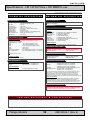
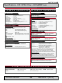
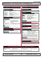
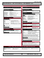
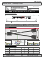
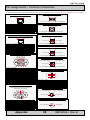
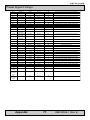
Pin Assignments - Common Connectors
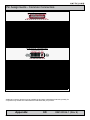
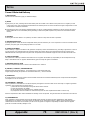
Pin Assignments - 25P Parallel
13 12 11 10 9 8 7 6 5 4 3 2 1
25 24 23 22 21 20 19 18 17 16 15 14
Pin 01 - STROBE
Pin 02 - DATA0
Pin 03 - DATA1
Pin 04 - DATA2
Pin 05 - DATA3
Pin 06 - DATA4
Pin 07 - DATA5
Pin 08 - DATA6
Pin 09 - DATA7
Pin 10 - ACK
Pin 11 - BUSY
Pin 12 - PE
Pin 13 - SELECT
Pin 14 - AUTO FEED
Pin 15 - ERR#
Pin 16 - INIT#
Pin 17 - SLIN#
Pin 18 - GND
Pin 19 - GND
Pin 20 - GND
Pin 21 - GND
Pin 22 - GND
Pin 23 - GND
Pin 24 - GND
Pin 25 - GND
This signal indicates to the printer that data at PD7..0 are valid.
Parallel data bus from PC board to printer. The data line are able to operate in PS/2 compatible bi-directional mode.
Same as Pin 02
Same as Pin 02
Same as Pin 02
Same as Pin 02
Same as Pin 02
Same as Pin 02
Same as Pin 02
Signal from printer indicating that the printer has received the data and is ready to accept further data.
Signal from printer indicating that the printer cannot accept further data.
Signal from printer indicating that the printer is out of paper.
Signal from printer to indicate that the printer is selected.
This active low output causes the printer to add a line feed after each line printed.
Signal from printer indicating that an error has been detected.
This active low output initialises (resets) the printer.
Signal to select the printer sent from CPU board to printer.
Ground
Ground
Ground
Ground
Ground
Ground
Ground
Ground
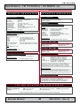
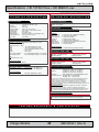
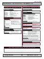
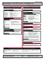
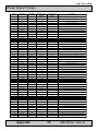
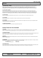
Pin Assignments - 24P DVI-D & DVI-I
1 2 3 4 5 6 7 8 C1 C2
9 10 11 12 13 14 15 16
C5
17 18 19 20 21 22 23 24 C3 C4
Pin 01
Pin 02
Pin 03
Pin 04
Pin 05
Pin 06
Pin 07
Pin 08
Pin 09
Pin 10
Pin 11
Pin 12
Pin 13
Pin 14
Pin 15
Pin 16
Pin 17
Pin 18
Pin 19
Pin 20
Pin 21
Pin 22
Pin 23
Pin 24
Pin C1
Pin C2
Pin C3
Pin C4
Pin C5
T.M.D.S. Data2 - (Digital - RED link 1)
T.M.D.S. Data2 + (Digital + RED link 1)
T.M.D.S. Data2/4 Shield
T.M.D.S. Data4 - (Digital - GREEN link 2)
T.M.D.S. Data4 + (Digital + GREEN link 2)
DDC Clock
DDC Data
Analog Vertical Sync (DVI-I only)
T.M.D.S. Data1 - (Digital - GREEN link 1)
T.M.D.S. Data1 + (Digital + GREEN link 1)
T.M.D.S. Data1/3 Shield
T.M.D.S. Data3 - (Digital - BLUE link 2)
T.M.D.S. Data3 + (Digital + BLUE link 2)
+5V Power (for standby mode)
Ground (for +5V and analog sync)
Hot Plug Detect
T.M.D.S. Data0 - (Digital - BLUE link 1) and digital sync.
T.M.D.S. Data0 + (Digital + BLUE link 1) and digital sync.
T.M.D.S. Data0/5 Shield
T.M.D.S. Data5 - (Digital - RED link 2)
T.M.D.S. Data5 + (Digital - RED link 2)
T.M.D.S. Clock Shield
T.M.D.S. Clock + (Digital clock + (Links 1 and 2)
T.M.D.S. Clock - (Digital clock - (Links 1 and 2)
Analog RED
Analog GREEN
Analog BLUE
Analog Horizontal Sync.
Analog Ground (return for RGB signals)
DDC = Display Data Channel /// T.M.D.S = Transition Minimized Differential Signal /// PIN C1,C2,C3,C4 = Only present on DVI-I connectors.
Additional connector pinouts may be available in third party motherboard manuals, primarly for
computers only. Please see manual/drivercd delivered with your product.
Appendix
IND100241-2
69
INB100026-1 (Rev 9)