1
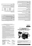
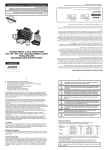
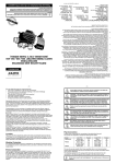
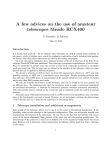
Operator Manual
High Yield Technology
9020 Plasma Particle Detector
HYT 9020 - Table of Contents
1 of 38
Table of Contents
1
Overview
2
9020 Plasma Particle Detector Performance Specifications
3
Installation
3.1
3.2
3.3
3.4
3.5
3.6
3.7
3.8
Unpacking and Handling.......................................................................... 9
Parts List for HYT 9020 Interceptor sensor.............................................. 9
Tools Needed......................................................................................... 10
Laser Safety Interlocks .......................................................................... 10
Precautions ............................................................................................ 10
Installation.............................................................................................. 10
Procedure for Aligning the HYT9020 Laser Module .............................. 18
Sensor Diagnostic Verification ............................................................... 23
4
Principals of Operation
5
Maintenance and Cleaning Procedures
5.1
6
Cartridge Window Removal / Replacement ........................................... 27
Troubleshooting
Appendix A: Service Procedures................................................35
Return Procedures................................................................................. 35
Technical Support Information ............................................................... 35
RPS - May 2007 - Edition 4
A.1
A.2
Operator Manual
Table of Contents - HYT 9020
RPS - May 2007 - Edition 4
2 of 38
Operator Manual
HYT 9020 - Manual Overview
3 of 38
Manual Overview
About This Manual
The information in this manual has been carefully checked and is believed to be accurate.
However, Hach Ultra Analytics assumes no responsibility for any inaccuracies that may be
contained in this manual. In no event will Hach Ultra Analytics be liable for direct, indirect,
special, incidental, or consequential damages resulting from any defect or omission in this
manual, even if advised of the possibility of such damages. In the interest of continued product
development, Hach Ultra Analytics reserves the right to make improvements in this manual and
the products it describes at any time, without notice or obligation.
Published in the United States of America
Hach Ultra Analytics P/N: 701245 Edition 1, June 2007
Copyright © 2007 by Hach Ultra
All rights reserved. No part of the contents of this manual may be reproduced or transmitted in
any form or by any means without the written permission of Hach Ultra Analytics.
Safety Conventions
WARNING
A warning is used to indicate a condition which, if not met, could cause serious personal injury
and/or death. Do not move beyond a warning until all conditions have been met.
CAUTION:
A caution is used to indicate a condition which, if not met, could cause damage to the
equipment. Do not move beyond a caution until all conditions have been met.
Note:
A note is used to indicate important information or instructions that should be considered
before operating the equipment.
General Safety Considerations
These safety guidelines should be read carefully and understood before operating the High
Yield Technology 9020 Plasma Particle Detector (HYT 9020).
RPS - June 2007 - Edition 1
• All service procedures should be conducted by properly trained service personnel.
• Make sure the HYT 9020 is properly installed and all connections are correctly made
before operation. All safety guidelines should be observed.
• Follow all procedures in “Return Procedures” on page 35 before shipping a unit to a
service center for repair or re-calibration.
WARNING
Only factory certified personnel should perform service of the HYT 9020. Attempts by
untrained personnel to disassemble, alter, modify or adjust the electronics and/or hydraulics
may result in personal injury and damage to the HYT 9020.
Operator Manual
4 of 38
Manual Overview - HYT 9020
Warranty
Hach Ultra Analytics warrants that this instrument will be free of defects in materials and
workmanship for a period of one (1) year from the shipping date. If any instrument covered
under this warranty proves defective during this period, Hach Ultra Analytics will, at its option,
either repair the defective product without charge for parts and labor, or provide an equivalent
replacement in exchange for the defective product.
To obtain service under this warranty, the customer must notify the nearest Hach Ultra
Analytics service support center on or before the expiration of the warranty period and follow
their instructions for return of the defective instrument. The customer is responsible for all costs
associated with packaging and transporting the defective unit to the service support center, and
must prepay all shipping charges. Hach Ultra Analytics will pay for return shipping if the
shipment is to a location within the same country as the service support center.
This warranty shall not apply to any defect failure or damage caused by improper use or
maintenance or by inadequate maintenance or care. This warranty shall not apply to damage
resulting from attempts by personnel other than Hach Ultra Analytics representatives, or
factory-authorized and trained personnel, to install, repair or service the instrument; to damage
resulting from improper use or connection to incompatible equipment; or to instruments that
have been modified or integrated with other products when the effect of such modification or
integration materially increases the time or difficulty of servicing the instrument.
THIS WARRANTY IS GIVEN BY HACH ULTRA WITH RESPECT TO THIS INSTRUMENT IN
LIEU OF ANY OTHER WARRANTIES, EXPRESSED OR IMPLIED. HACH ULTRA
ANALYTICS AND ITS VENDORS DISCLAIM ANY IMPLIED WARRANTIES OF
MERCHANTABILITY OR FITNESS FOR A PARTICULAR NON-CONTRACTUAL PURPOSE.
HACH ULTRAS’ RESPONSIBILITY TO REPAIR OR REPLACE DEFECTIVE PRODUCTS IS
THE SOLE AND EXCLUSIVE REMEDY PROVIDED TO THE CUSTOMER FOR BREACH OF
THIS WARRANTY. HACH ULTRA AND ITS VENDORS WILL NOT BE LIABLE FOR ANY
INDIRECT, SPECIAL, INCIDENTAL, OR CONSEQUENTIAL DAMAGES EVEN IF HACH
ULTRA OR ITS VENDORS HAS BEEN GIVEN ADVANCED NOTICE OF THE POSSIBILITY
OF SUCH DAMAGES.
Revision History
RPS - June 2007 - Edition 1
• Edition 1, June 2007, Hach Ultra
Operator Manual
HYT 9020 - Overview
1
5 of 38
Overview
The 9020 Plasma Particle Detector from Hach Ultra Analytics, High Yield Technology (HYT)
Division, is a bright field particle sensor for In Situ Particle Monitoring (ISPM), designed for use
in closed vacuum pump lines and process chambers, with no conductance loss. Bright field
detection enables use of this sensor in plasma or high ambient light environments.
The sensor consists of three components; a visible semiconductor laser diode source, photo
diode detector, and detector/laser driver module. The Laser and Detector Modules occupy
opposing ports on the vacuum enclosure. The laser beam traverses the interior of the vacuum
enclosure allowing detection of particles entrained in the gas flow.
The sensor is optically coupled to the vacuum enclosure through sapphire windows mounted
in cartridge windows for ease of maintenance. Cartridge Windows may be replaced without
moving the sensor. Closed loop temperature control is utilized to maintain sensor stability and
long laser life.
A dual vacuum switch connected to the vacuum enclosure provides an interior access safety
interlock when internal pressure reaches 500 Torr. Internal magnetic sensors in the laser and
detector modules provide an exterior access safety interlock.
RPS - June 2007 - Edition 1
Hach Ultra Analytics is the leader in vacuum in situ particle monitoring and provides
comprehensive user training and support, a VLSI applications engineering group, and a wide
range of proven applications.
Fig 1-1 : 9020 Adapter Flange
Operator Manual
Overview - HYT 9020
RPS - June 2007 - Edition 1
6 of 38
Operator Manual
HYT 9020 - 9020 Plasma Particle Detector Performance Specifications
2
7 of 38
9020 Plasma Particle Detector Performance Specifications
Minimum Size Sensitivity
0.22 µm at nominal focal length, 1.5 to 1.0 signal-to-noise*
False Count Rate
1 count per 4 hours at 95% UCL
Average of 1 count per 12 hours at 1.5-to-1.0 signal-to-noise
Detection Area
1 mm2 at 0.27 µm
3 mm2 at 0.35 µm
5 mm2 at 0.50 µm
Laser
405 nm wavelength 30 mW emitted power
Plasma-Exposed Materials
300 series stainless steel
Magnesium fluoride coated sapphire
Vacuum/Pressure Range
9.0 X 10⁻⁸ torr to 100 psi
Temperature Range
0 to 45 °C ambient operating
Up to 65 °C at the windows (heated window/manifold)
Certifications
Laser Safety: FDA Title 21, Subchapter J compliance,
accession number 9922627-02, class 3b laser and class 1
product CE emissions, immunity and safety: EN 55011, 61326,
61000, and 60825
Controller Firmware Compatibility
CONTROLLER FIRMWARE VERSION
PM250 Series
5.63 or later
PM450 Series
1.9 or later
Detector and Laser Cable Lengths VERSION
DETECTOR CABLE
LASER CABLE
9020A
30 inches / 76.2 CM
30 inches / 76.2 cm
9020B
45 inches / 114.3 cm
30 inches / 76.2 cm
9020C
60 inches / 152.4 cm
30 inches / 76.2 cm
RPS - June 2007 - Edition 1
* 0.19 µm minimum sensitivity
Operator Manual
9020 Plasma Particle Detector Performance Specifications - HYT 9020
RPS - June 2007 - Edition 1
8 of 38
Operator Manual
HYT 9020 - Installation
3
9 of 38
Installation
This section of the manual describes the installation of the 9020 Plasma Particle Detector and
the connections with external equipment. If necessary, consult the High Yield Technology
(HYT) Technical Support Department to resolve any questions of compatibility or suitability of
this product for a specific application.
3.1 Unpacking and Handling
All packages (pink anti-static bags) are to be opened in a clean room only. Parts should not be
removed from bags until ready to install. When working on sub-assemblies, parts should be
placed on a clean surface or lint free wipes. All parts should be handled with fab approved
clean room gloves.
RPS - June 2007 - Edition 1
3.2 Parts List for HYT 9020 Interceptor sensor
Item
Part Number
Laser Module
2088205-0X (X = Version: 1=A, 2=B, 3=C)
Detector Module
2088206-01
Driver Module
2088216-01
Mounting Block Assemblies (2)
2088245-01 (attached to laser and detector during shipping)
Insulator Mount for Laser Module
2088207-01 (attached to laser module during shipping)
Insulator Mount for Detector Module
2088208-01 (attached to detector module during shipping)
Laser Alignment Module
2088234-01 (attached to laser module during shipping)
Cartridge Windows (4)
2088270-01
Pressure Interlock Switch kit
2088264-01
Laser Module Cable
2088267-01
Detector Module Cable
2088268-0X (X = Version: 1=A, 2=B, 3=C)
Sensor Cable, HYT 9020 to PM250 Controller
8000-1724-25
If PM450: Sensor Cable, HYT 9020 to PM450 Controller
2084440-25
Interlock Adapter Cable, BNC - 2 pin Molex
2088265-01A
Spare Sapphire Windows, 405 Coating (4)
2088204
Spare O-Rings, 2-015, Viton (4)
A000-0302
Spare O-Rings, 2-019, Viton (4)
A000-0303
3/32 Ball Hex Driver
680-000-3061
5/64 Ball Hex Driver
680-000-3053
5/64 Right Angle Hex Wrench
995925
Laser Alignment Fixture
2088263-01
Interlock bypass Key
450-100-3500
PM250/450 Interlock Bypass Connector
2088272-01
Operator Manual
10 of 38
Installation - HYT 9020
3.3 Tools Needed
•
•
•
•
Small flat blade screw driver
Allen wrenches, 3/32", 5/64" (Provided)
3/4" open end wrench
Open end adjustable wrench
3.4 Laser Safety Interlocks
The 9020 sensor contains three, dual redundant, safety interlocks that will shut off the laser if
any one of these six switches are opened. The Laser and Detector Modules each contain two
internal Magnetic Interlock Switches. The Insulator Mounts contain internal magnets that line
up with the interlock switches. If either Module is removed, the laser will shut off. The 9020
sensor also uses a Dual Pressure Interlock Switch that is installed on the vacuum side of the
chamber to be monitored. If the chamber pressure is > 500 Torr, the laser will shut off.
3.5 Precautions
• Attach all electrical cabling before applying power anywhere in the system.
• NEVER make, or break, electrical connections when equipment is powered ON.
• Do not attempt to defeat any interlocks on the product as this could permit access to
harmful invisible laser radiation. (Exception: Trained personnel during laser alignment)
• Do not attempt to open any non-interlocked ports during operation or routine
maintenance that could allow access to laser energy.
3.6 Installation
The following instructions will guide the user through the installation of the HYT 9020 sensor.
Note:
RPS - June 2007 - Edition 1
The HYT 9020 sensor is calibrated as a set; Laser Module, Detector Module, and Driver
Module. The serial number is marked on each component. The components cannot be
exchanged or mixed with other HYT 9020 sensors.
Operator Manual
HYT 9020 - Installation
3.6.1
11 of 38
Preparation
Because the Sensor Modules are shipped attached to the Mounting Blocks, it will be necessary
to remove the Sensor Modules, the Alignment Module on the Laser Module side, and the
Insulator Mounts, to access the screws for the Mounting Blocks. The Insulator Mounts are
unique to each Module and must stay with the correct component. The Insulator Mounts are
marked "L" for Laser and "D" for Detector. The Laser and Detector Module components are
displayed in Figure 3-1.
Note:
All screws used in the assembly of the sensor modules are captive screws.
Fig 3-1 : Sensor Modules
1)
2)
RPS - June 2007 - Edition 1
3)
4)
5)
Loosen the Thumbscrew in back of the Laser Module and slide the heat sink off.
Remove the four screws in each module (Laser and Detector) to separate the module
from the mounting hardware.
On the Laser side, remove the Alignment Module by loosening the four recessed
screws. See Figure 3-3.
Remove the Insulator Mounts (four screws each side) from both Mounting Blocks. See
Figure 3-5 on page 14 and Figure 3-6 on page 15.
The Mounting Blocks are now ready to install.
Operator Manual
12 of 38
Installation - HYT 9020
Determine the correct orientation of the HYT 9020 Sensor Modules and Mounting Blocks
for the application. For maximum detection area the Sensor Modules (Laser and Detector)
should be installed with the module cables perpendicular to exhaust flow or particle flow. See
Figure 3-2. Both Sensor Modules must be in the same orientation. The Mount Blocks are
open on one side to allow the Cartridge Window to be slid into place. The Mounting Blocks will
need to be orientated such that the Cartridge Window can be accessed (removed/replaced)
without removing the Sensor Module or Mounting Block. See Figure 3-4.
Note:
If it is necessary to rotate the Sensor Modules on the Mounting Blocks to obtain the desired
orientation, the Insulator Mounts and Laser Alignment Module must also be rotated in the
same direction so that the interlock switches line up. Note that the components are keyed, and
can only fit together one way. See Figure 3-3, Figure 3-5 on page 14 and Figure 3-6 on
page 15.
Fig 3-3 : Laser Alignment Module
Operator Manual
RPS - June 2007 - Edition 1
Fig 3-2 : Sensor Module Cable Connectors Perpendicular to Flow
HYT 9020 - Installation
3.6.2
13 of 38
Installation
1)
Install the two Mounting Blocks on the manifold or chamber using the 4-40 x 1" socket
head screws provided. The Mounting Blocks are the same, so it doesn't matter which
one goes on which side.
Note:
One side of the Mounting Block is open to allow the cartridge window to be slid in to place.
Install each Mount Block so the opening for the Cartridge Window is facing out.
(See Figure 3-4.)
Do not install Cartridge Windows until step 3.
Fig 3-4 : Mounting Blocks
2)
3)
RPS - June 2007 - Edition 1
4)
Back off (turn counter clockwise) the four Set Screws that secure the Cartridge Window
in each Mounting Block (use 3/32" driver provided). Note that these screws are not
capture screws. See Figure 3-4. These four screws will still be accessible even after
the Insulator Mounts and sensor modules are installed, so windows can be serviced
without removing any other hardware. See “Cartridge Window Removal /
Replacement” on page 27.
Install the Cartridge Windows in the Mounting Blocks making sure the o-ring is facing
the chamber, manifold, or spool piece (vacuum seal) and the alignment pin is aligned
with the notch in the Mounting Block. Insure Cartridge Window is all the way in and
Laser Beam Bore is completely open. See Figure 3-4.
Tighten the four Set Screws against the Cartridge Window in a cross pattern, a few
turns at a time, until Set Screw contacts the Cartridge Window. At this point tighten the
Set Screws ¼ turn at a time until tight.
Operator Manual
14 of 38
Installation - HYT 9020
5)
Install Insulator Mounts on the Mounting Blocks. Recall that the Laser and Detector
Insulator Mounts are unique to each Sensor Module, and should be installed on the
recommended side for the particular application, usually the side, which allows the
most room for access to the Laser, for Laser Alignment. Also verify that the Insulator
Mount is in the correct orientation to match up to the Alignment Module and the Laser
Module, as all components are keyed (indexed). See Figure 3-5 and Figure 3-6.
Fig 3-5 : Laser Components
Verify the Detector Module Insulator is in the desired orientation with the Detector
Module. Install the Detector Insulator. See Figure 3-6.
RPS - June 2007 - Edition 1
6)
Operator Manual
HYT 9020 - Installation
15 of 38
Fig 3-6 : Detector Module Components
7)
8)
RPS - June 2007 - Edition 1
9)
Install the Laser Alignment Module on the Laser side Insulator Mount. See Figure 3-4
on page 13 and Figure 3-5 for mounting screw location.
Install the Laser Module on the Alignment Module. Note that the Laser Module is keyed
to the Alignment Module and will only go on in one position. See Figure 3-5. Do not
install the Detector Module until after Laser Alignment.
Install the Pressure Interlock Switch (P/N 2088264-01) with VCR gasket on the 90°
adapter using a ¾" open-end wrench. Install the Pressure Interlock Switch in a process
vacuum line (example: T into pressure manometer line) so the Pressure Switch sees
the same pressure as the chamber. Note: The Pressure Interlock Switch will shut off
the Laser if chamber pressure is > 500 Torr.
Operator Manual
16 of 38
Installation - HYT 9020
10)
11)
Place the 9020 Driver Module between the Laser and Detector Modules, away from
high temperature and electrical interference, in a safe place on the process tool.
Ensure the Driver Module is sitting on its non-conductive pads. Mounting holes are
available on the bottom of the pads, should the user want to secure the Driver Module
or mount in a vertical position.
Select the Laser Module Cable (P/N 2088267-01) and plug it into the Laser Module.
Plug the other end into the connector marked Laser on the Driver Module. See
Figure 3-7 and Figure 3-8.
Fig 3-7 : Driver Module
12)
Select the Detector Module Cable (P/N 2088268-0X) and plug it into the Detector
Module. Plug the other end of the cable (with RFI suppressor) into the connector
marked Detector, on the Driver Module. See Figure 3-7 and Figure 3-8.
Note:
RPS - June 2007 - Edition 1
The Detector Module is not yet installed on the process tool.
Operator Manual
HYT 9020 - Installation
17 of 38
Fig 3-8 : HYT 9020 Wiring Diagram
13)
14)
RPS - June 2007 - Edition 1
15)
Connect the 9020 Sensor Cable (P/N 8000-1724-25 or 2084440-25) from the Control
location on the Driver Module to the PMXXX Controller. See Figure 3-7 and Figure 3-8.
Connect the 26-pin Trigger Adapter Cable to PM250 Controller (if PM250 Controller
used). The 26-pin Trigger Adapter Cable is supplied with the PM250 Controller.
Connect the Controller Interlock Bypass Connector (P/N 2088272-01) to the BNC
connection on the 26-pin Trigger Adapter Cable (If PM250 Controller used). If a PM450
Controller is used, connect the Interlock Bypass Connector to the BNC interlock
connector on back of the Controller. See Figure 3-9.
Fig 3-9 : BNC Terminator for PM250/PM450
Operator Manual
18 of 38
Installation - HYT 9020
16)
17)
18)
19)
Connect the Interlock Cable (P/N 2088266-01), the BNC end to the BNC Adapter on
the Pressure Interlock Switch, and the other end to the Interlock connector on the
Driver Module. See Figure 3-7 and Figure 3-8.
Connect RS232 Cable from PM250 Controller to PC (if PM250 Controller used). RS232
Cable supplied with PM250 Controller.
Connect power cord from PMXXX Controller to 110/220V AC outlet.
The next step is Laser Alignment.
3.7 Procedure for Aligning the HYT9020 Laser Module
3.7.1
Equipment
•
•
•
•
•
Model HYT 9020 Laser Particle Counter System
Alignment Target
3/32" x 5.5" Ball Hex Driver
5/64" x 5.0" Ball Hex Driver
5/64" Right Angle Hex Wrench
CAUTION:
Do not stare directly into the Laser Beam. The Laser is capable of causing eye damage.
Only with the correct equipment can the Laser Beam be viewed.
Procedure
1)
2)
3)
Operator Manual
Assemble the 9020 Laser Module onto the manifold with the cable in the correct
orientation. There are 2 possible positions for the cable connector to locate. In the case
where the flow is down, the connector will be pointing either as shown in Figure 3-10 or
180° opposite, depending on routing or clearance needs for the cable. The final
position should be determined before the alignment since rotating the module after
alignment may require realignment.
Remove the Thumbscrew in the back of the Laser Module and remove the Laser
Module Cover (heat sink). (If first time installation, the Laser Module Cover will not yet
be installed.)
Do not turn the Alignment Locking or Adjusting Screws at this time. The system is prealigned and locked down at the factory meaning it may or may not need realigning once
installed on the manifold.
RPS - June 2007 - Edition 1
3.7.2
HYT 9020 - Installation
19 of 38
Fig 3-10 : Cable Connector Position
4)
5)
Figure 3-10 also shows screw assignments. The set of 4 screws are repeated every 90
degrees. Note that the Alignment Adjusting Screws are at the horizontal and vertical
locations with respect to the laser beam to aid in the alignment process.
Inspect the Alignment Target for damage such as cracks or missing components. It has
a black glass side and a frosted glass (diffuser) side. Both pieces must be in place and
not loose. The Target allows for eye safe direct viewing of the Laser as long as it
is in place and undamaged. Otherwise, do not stare into the raw Laser Beam.
CAUTION:
Never apply power to the system unless the Detector Module or Target are in place.
6)
RPS - June 2007 - Edition 1
7)
Remove the four screws holding the Detector Module to the Insulator Mount and
remove the Detector Module. (If first time installation, the Detector Module will not yet
be installed.)
Attach the Alignment Target shown in Figure 3-11 to the Insulator Mount on the
Detector Module side. The screws holding the Target onto the Insulator Mount will use
the same holes as the mounting of the Detector Module. The Detector Module does not
need to be connected to the Driver Module at this time.
Operator Manual
20 of 38
Installation - HYT 9020
Fig 3-11 : Attach Alignment Target
8)
Defeat the Interlocks by placing the Interlock Bypass Key in the Bypass Socket on the
Driver Module. The Interlock LED on the Driver Module will be RED. See Figure 3-12.
CAUTION:
Extreme care must now be taken, as the modules can be removed with the laser power on.
RPS - June 2007 - Edition 1
Fig 3-12 : Install Bypass Key
Operator Manual
HYT 9020 - Installation
21 of 38
9)
10)
Turn the system on and enable the laser. (The PM250 Controller can use PV Scope or
Particle Vision to enable the laser.) Do not stare into the Target yet. Place a sheet of
white paper about 12" away from the Target and determine if a bright blue laser spot
can be seen. If so, do not stare into the Target. Replace the Target or determine what is
wrong. If a low intensity blue glow is seen on the paper, then it is safe to stare into the
Target.
The Laser Beam should be viewable on the Target. If the Laser Beam is entirely within
the black circle, then the beam does not need to be aligned. Turn off the laser power,
remove the Target and install the Detector Module. Figure 3-13 shows a Laser needing
the alignment adjusted and a correctly aligned laser.
Fig 3-13 : Laser Alignment
11)
12)
RPS - June 2007 - Edition 1
13)
If the laser beam is spilling over more than half way around the black circle then the
beam needs to be aligned.
There are 8 screws involved in aligning the Laser, 4 Alignment Adjusting Screws and 4
Alignment Locking Screws. One Adjustment Screw under the connector, which can't be
seen in Figure 3-10 on page 19 and Figure 3-14 because of the connector, requires the
5/64" Right Angle Hex Wrench to adjust it. The remaining Adjustment Screws use the
5/64" Ball Hex Driver. The Locking Screws use the 3/32" Ball Hex Driver. It may be
possible, in tight applications, to not have to adjust the set of screws under the
connector, depending on how far the laser beam is out of alignment. This will be
described later. See Figure 3-10 on page 19 and Figure 3-14.
The adjustments work as follows. To raise and lower the laser beam, the top and
bottom Adjustment Screws are used. To move the laser beam from side to side the
right and left Adjustment Screws are used. They must be used together to move the
laser beam up or down or right or left. Descriptions are shown in Figure 3-14.
Operator Manual
22 of 38
Installation - HYT 9020
14)
15)
16)
17)
18)
19)
20)
21)
22)
Operator Manual
The Locking Screws may not all need to be loosened, depending on which way the
laser beam needs to go. For example, if the laser beam needs to move up, then the
right and left Locking Screws don't need to be loosened. In the case where the laser
beam needs to move up, loosen the top Locking Screw by turning it counter clockwise.
First turn the bottom Adjusting Screw counter clockwise a small amount and then turn
the top Adjusting Screw clockwise the same amount. View the location of the laser
beam. Two people work best for this for immediate feedback. After the laser beam is
put within the black circle, tighten the Lockdown Screws the same amount. If one is
tightened more than the other, the laser beam may shift slightly.
Use the same procedure for the horizontal movement of the laser beam as the vertical
movement of the beam.
To move in a diagonal direction, a combination of vertical and horizontal adjustments
will need to be made. In this case it would be best to loosen all of the Locking Screws.
If the adjustments get too tight, it may be because the Adjustment Screws are all turned
in too far. Or, if the laser beam cannot be seen in the Target, you may need to start
over. If this happens back off all of the Adjustment Screws until free and start over by
adjusting each one clockwise until they just begin to get tight.
If the Screw under the connector cannot be accessed with the Right Angle Hex
Wrench. Use that location as a pivot point and tighten and loosen the remaining sets of
screws around it to adjust the location of the laser beam.
After all adjustments are finished, make sure the Locking Screws are tight.
Turn off the HYT Controller power and remove the Interlock Bypass Key from the Driver
Module.
Then remove the Alignment Target and install the Detector Module.
Power on the HYT Controller. The three LED's on the driver module (Interlock, Laser,
Temp) should all turn green after two or three minutes of warm up.
RPS - June 2007 - Edition 1
Fig 3-14 : Adjustments
HYT 9020 - Installation
23 of 38
3.8 Sensor Diagnostic Verification
1)
2)
Power on the PMXXX Controller and allow sensor to warm up at least 20 minutes.
Verify Laser Current is within +/- 2mA of the value on the Q/C sheet shipped with
sensor or on the calibration sticker on Driver Module. If the Laser Current is more than
2 mA different from the calibration sticker, contact HYT for recommendations.
3) Verify Stray Light is > 50. Stray light value will automatically toggle between channels
A and B every few seconds. Therefore, the value may change slightly every few
seconds, but shouldn't change by more than 3 points. If Stray Light does change by
more than three points, recheck laser alignment. Note: In some applications the Stray
Light value will drop as the Windows become coated with by-products of the process.
When the minimum Stray Light Value (default lower limit = 40) is reached, the windows
will need to be cleaned or replaced. See “Cartridge Window Removal / Replacement”
on page 27.
4) Verify Median Noise is between 5 and 15. If Median Noise is > 15, an alignment issue
may exist or Windows may be contaminated. Windows can be removed and inspected
through access holes for Cartridge Windows in mounting bracket. Refer to “Cartridge
Window Removal / Replacement” on page 27.
The Upper and Lower Control Limits for the 9020 Sensor are shown in Figure 3-15.
RPS - June 2007 - Edition 1
Fig 3-15 : Upper and Lower Control Limits
Operator Manual
Installation - HYT 9020
RPS - June 2007 - Edition 1
24 of 38
Operator Manual
HYT 9020 - Principals of Operation
4
25 of 38
Principals of Operation
Unlike the other HYT sensors, which detect scattered light, the 9020 Plasma Particle Detector
uses Bright Field technology to detect particles. Bright Field sensors have the laser beam
focused directly into the photo detectors. They detect particles by measuring change in the
laser beam when a particle passes through the beam.
In the case of 9020 Plasma Particle Detector, the laser beam is split into two parallel beams,
one going to one photo detector (Channel A) and the other to a second photo detector
(Channel B). When a particle passes through one of the beams, there is a change in the signal
seen at that detector, and if this change in the signal is large enough to cross over one of the
preset particle thresholds, it is captured as a particle. Any change, if large enough, seen on one
channel but not the other channel is captured as a particle. Any interference or change in the
signals seen on both photo detectors, such as plasma light, is cancelled out (common mode
rejection).
Complete in situ particle monitoring systems include the Plasma Particle Detector, an HYT
PM-XXX Controller, Machine Trigger capability, which provides synchronization of particle
counts with the process cycle, and Particle Vision II ® software for data acquisition and
analysis. Only HYT provide full time system diagnostics. Used in conjunction with an HYT
controller, the Plasma Particle Detectors facilitate process control by enabling users to monitor
particles continuously and in real time.
RPS - June 2007 - Edition 1
Fig 4-1 : Operation
•
•
•
•
•
•
•
Two beams of orthogonally polarized light
A prism splits the polarized light, directing it to separate photocells (A and B)
Particles scatter different amounts of each polarization
Differential of the two signals determines the final signal (A - B)
Non-polarized light (e.g. plasma) creates an equal signal and is cancelled
Short-wavelength blue laser for improved size sensitivity
HYT-patented technology
Operator Manual
Principals of Operation - HYT 9020
RPS - June 2007 - Edition 1
26 of 38
Operator Manual
HYT 9020 - Maintenance and Cleaning Procedures
5
27 of 38
Maintenance and Cleaning Procedures
5.1 Cartridge Window Removal / Replacement
1)
2)
3)
Verify that the chamber or exhaust line where the sensor is located, has been vented
(atmospheric pressure) and it is safe to work on the tool.
Turn off power to the HYT controller.
Locate the four holes in each sensor module (Laser and Detector) that access the Set
Screws for the Cartridge Windows. See Figure 3-10 on page 19 and Figure 5-1 below.
Fig 5-1 : Access Holes
4)
RPS - June 2007 - Edition 1
5)
6)
Insert the 3/32" Ball Driver (provided) into the holes one at a time and gently loosen the
four Set Screws in each Module until they stop turning against the Insulator Mount. Do
not force them any further.
Remove the Cartridge Windows using the knurled handle. See Figure 5-1.
At this point, either obtain new or serviced Cartridges, or clean / replace the Windows in
the existing Cartridges.
Operator Manual
28 of 38
Maintenance and Cleaning Procedures - HYT 9020
5.1.1
Cartridge Window Service
Equipment Needed
•
•
•
•
•
•
Small needle noise pliers or spanner wrench
O-ring removal tool or similar non-metal tool
Lint free wipers
Cleaning solution - IPA, Acetone, DI Water
Bright light for window inspection (adjustable flashlight may work)
Clean room gloves
Procedure
Note:
Cartridge Windows should only be serviced in a clean room and handled with fab approved
clean room gloves.
RPS - June 2007 - Edition 1
A) Before removing the window from the cartridge, inspect the window under a bright
light for any deposition, coating or film. If the window has visible coating, a film or
haze, proceed to step II.
B) Unscrew the black Retaining Ring using a spanner wrench, or the tips of a small
pair of needle nose pliers. See Figure 5-2.
C) With the o-ring removal tool or similar device, carefully lift the edge of the window
from the cartridge just high enough that it can be picked up by the edges. Now
completely remove the window handling it only by the edges.
D) Place the window in the center of a lint free wiper that is saturated with IPA or
Acetone. In some applications, DI water will work.
E) Fold the lint free wiper in half with the window enclosed in the center. Firmly rub the
Window in between the halves of the lint free wiper with the fingers and thumb.
F) Transfer the window to a dry lint free wiper and again fold in half and rub the
window between the fingers and thumb. Holding the window by the edges, inspect
the window under a bright light. The window should be completely clear, no coating
or haze.
G) Remove the old o-rings from the cartridge with the o-ring removal tool.
H) Carefully clean the cartridge with IPA or DI water. Use Nitrogen or Clean Dry Air to
dry the cartridge.
I) Install new o-rings in the Cartridge and reinstall the window.
Operator Manual
HYT 9020 - Maintenance and Cleaning Procedures
29 of 38
Fig 5-2 : Unscrew Retaining Ring
7)
8)
RPS - June 2007 - Edition 1
9)
Install the new or refurbished Cartridge Window in the Mounting Block opening, while
making sure the o-ring stays in the o-ring groove, and is on the side of the process
chamber.
Tighten the four Set Screws in each Module against the Cartridge Window in a cross
pattern, a few turns at a time, until Set Screw contacts the Cartridge Window. At this
point tighten the Set Screws ¼ turn at a time until tight.
Turn the HYT Controller power back on and verify the 9020 Sensor diagnostics
(see “Sensor Diagnostic Verification” on page 23).
Operator Manual
Maintenance and Cleaning Procedures - HYT 9020
RPS - June 2007 - Edition 1
30 of 38
Operator Manual
HYT 9020 - Troubleshooting
6
31 of 38
Troubleshooting
Note:
The HYT Controllers have software that enable the user to check the sensor diagnostics. For
the HYT PM250 controllers, use Particle Vision II software (example shown in Figure 3-15 on
page 23). For HYT PM450 users, the sensor diagnostics can be viewed from the PM450 web
site.
Table 6-1 : Troubleshooting
RPS - June 2007 - Edition 1
Symptom
Resolution
Interlock and Laser
LED's do not turn on,
or do not turn green,
on Driver Module
1)
High Laser Current
(> 115% of last
calibration)
1)
Low Laser Current or
zero Laser Current
1)
2)
2)
2)
3)
Verify Sensor Module cables are fully plugged into the Driver Module and Sensor
Module connections.
Verify that the Interlock Pressure Switch is under vacuum and connected to the Driver
Module. If the Interlock Pressure Switch is under vacuum and the output through the
BNC connector is in a closed state (zero ohms), then it may be necessary to remove the
Laser and Detector Modules and verify the small cylindrical magnetic switch in the nose
piece is lined up with the magnets in the PEEK mounts. See figure below.
The ambient temperature or the manifold temperature exceeds the 9020 sensor
temperature upper limits (45°C Ambient, 65°C surface).
The laser diode has expired, and needs replacement by HYT Factory Service.
The Laser Module is unplugged or not fully plugged into the Driver Module. Check Laser
Module Cable connections.
There is an open interlock, which has shut off laser power. See Interlock verification
above.
There is an open circuit within the Laser Module or Driver Module. This will require HYT
Factory Service.
Operator Manual
32 of 38
Troubleshooting - HYT 9020
Table 6-1 : Troubleshooting (Continued)
Symptom
Resolution
High Stray Light
1)
2)
Low Stray Light or
zero Stray Light
1)
2)
3)
4)
High Median Noise
The Sapphire Windows have become dirty or coated. See “Cartridge Window
Removal / Replacement” on page 27 for for window maintenance instructions.
The Optical Filter (visible round filter glass at end of Detector Module) on the Detector
Module has become dirty or contaminated. The Optical Filter can be cleaned with IPA
and a lint free wiper.
Verify laser alignment. See “Procedure for Aligning the HYT9020 Laser Module”
on page 18 for laser alignment instructions.
2)
The Sapphire Windows may have become dirty or coated. See “Cartridge Window
Removal / Replacement” on page 27 for for window maintenance instructions.
The Optical Filter (visible round filter glass at end of Detector Module) on the Detector
Module has become dirty or contaminated. The Optical Filter can be cleaned with IPA
and a lint free wiper.
The sensor is picking up vibration. Place your hand on the sensor modules and feel for
excess vibration (possible bad turbo pump, isolation valve, or gate valve).
Light interference. There may be certain light intensities or wavelengths that may
elevate the Median Noise level. If High Median Noise is intermittant, check for
correlation to process steps that may interfere with the sensor. It may be possible to
tune out the noise. Check with HYT representitive for assistance.
Electrical Interference. In rare cases, high voltage or RF can be picked up by the
sensor. Make sure sensor cables are not routed near RF or high voltage cables.
4)
5)
6)
A-B channel
imbalance > 3
The Detector Module is unplugged or not fully plugged into the Driver Module. Check
cable connections.
Recheck laser alignment. See “Procedure for Aligning the HYT9020 Laser Module”
on page 18 for laser alignment instructions.
1)
3)
Low Median Noise
The Detector Module is plugged into the Driver Module but the Detector Module itself is
not installed on the mount. (Interlock Bypass Key would have to be installed for this
scenerio.)
The Detector Module has failed, and will require HYT Factory Service.
1)
2)
3)
Laser power off (open interlock), or Laser Module unplugged. Laser Current will also be
low. Check cable connections and interlocks.
Detector Module unplugged. Check cable connections.
The Sapphire Windows may have become coated over, blocking the laser beam. See
“Cartridge Window Removal / Replacement” on page 27 for for window
maintenance instructions. The Stray Light Diagnostic may also be low.
1)
2)
Verify laser alignment.
Make sure nothing is in the path of the laser beam.
The analog noise level can be viewed using PV Scope (PM250) or WEB Scope (PM450). This
can be useful when troubleshoot a possible sensor problem or application problem. An
example of PV scope (normal baseline) is shown in Figure 6-1. An example of interference
causing high noise is shown in Figure 6-2.
Operator Manual
RPS - June 2007 - Edition 1
Note:
HYT 9020 - Troubleshooting
33 of 38
RPS - June 2007 - Edition 1
Fig 6-1 : PV Scope (Normal Baseline)
Fig 6-2 : Interference Causing High Noise
Operator Manual
Troubleshooting - HYT 9020
RPS - June 2007 - Edition 1
34 of 38
Operator Manual
HYT 9020 - Service Procedures
35 of 38
Appendix A: Service Procedures
A.1 Return Procedures
To return the High Yield Technology 9020 Plasma Particle Detector for service, complete the
appropriate form that appears at the end of this section. For the most recent return procedure
information, including copies of all required forms, call Hach Ultra Analytics at 800.866.8854 or
+1 541.472.6500.
To return an instrument for credit, please contact the local sales representative.
WARNING
The following actions must be performed when returning any unit for any reason to prevent
personal injury and/or damage to the unit.
• If installed, remove the CO2 bottle from the unit and/or bottles from the carrying case. It
is unlawful to ship filled CO2 bottles in the USA due to their high-pressure contents. The
service center does not require use of customer CO2 bottles.
• Flush the system with clean 5606 hydraulic fluid. The service center technicians
must handle the fluids within the unit when performing a service. If flushing is not
possible, indicate what type of fluid is in the unit and if any safety precautions should be
followed during servicing.
• Place the caps supplied with the unit over the sample and drain tubes to prevent fluid
from leaking from the unit during shipment and causing damage to the internal
electronics.
• Wipe the unit down to remove any fluid from the outside surfaces of the unit to prevent
fluid from leaking from the unit during shipment and causing damage to the internal
electronics.
• Empty the waste container.
• Remove the sample bottle from the sample adapter.
A.2 Technical Support Information
Technical Support Engineers are available to provide high quality advice and
recommendations for applications, product operation, measurement specifications, hardware
and software, factory and customer site training.
RPS - June 2007 - Edition 1
Please provide name, company, phone, fax, model number, serial number and comment or
question.
Call +1 (541) 472-6500
Toll Free (800) 866-8854 (US/CA)
Fax +1 (541) 474-7414
6:00 AM to 5:00 PM Pacific Time
Monday through Friday
E-mail: [email protected]
Operator Manual
Service Procedures - HYT 9020
RPS - June 2007 - Edition 1
36 of 38
Operator Manual
HYT 9020 - User Notes
37 of 38
RPS - June 2007 - Edition 1
User Notes
Operator Manual
User Notes - HYT 9020
end of the book
Operator Manual
RPS - June 2007 - Edition 1
38 of 38
Global Headquarters
6, route de Compois C.P. 212
CH-1222 Vesenaz, Geneva, Switzerland
Tel + 41 (0)22 594 64 00
Fax + 41 (0)22 594 64 99
Americas Headquarters
481 California Avenue
Grants Pass, Oregon 97526 USA
Tel 1 800 866 7889 / +1 541 472 6500
Fax +1 541 472 6170
www.hachultra.com
© 2007 Hach Ultra Analytics, Inc.
All rights reserved. Trademarks are property of their respective owners. Specifications are subject to change without notice.