1
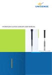
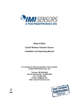
Model 130A23 ICP® Electret Array Microphone Installation and Operating Manual For assistance with the operation of this product, contact PCB Piezotronics, Inc. Toll-free: 800-828-8840 24-hour SensorLine: 716-684-0001 Fax: 716-684-0987 E-mail: [email protected] Web: www.pcb.com Warranty, Service, Repair, and Return Policies and Instructions The information contained in this document supersedes all similar information that may be found elsewhere in this manual. Total Customer Satisfaction – PCB Piezotronics guarantees Total Customer Satisfaction. If, at any time, for any reason, you are not completely satisfied with any PCB product, PCB will repair, replace, or exchange it at no charge. You may also choose to have your purchase price refunded in lieu of the repair, replacement, or exchange of the product. Service – Due to the sophisticated nature of the sensors and associated instrumentation provided by PCB Piezotronics, user servicing or repair is not recommended and, if attempted, may void the factory warranty. Routine maintenance, such as the cleaning of electrical connectors, housings, and mounting surfaces with solutions and techniques that will not harm the physical material of construction, is acceptable. Caution should be observed to insure that liquids are not permitted to migrate into devices that are not hermetically sealed. Such devices should only be wiped with a dampened cloth and never submerged or have liquids poured upon them. Repair – In the event that equipment becomes damaged or ceases to operate, arrangements should be made to return the equipment to PCB Piezotronics for repair. User servicing or repair is not recommended and, if attempted, may void the factory warranty. Calibration – Routine calibration of sensors and associated instrumentation is recommended as this helps build confidence in measurement accuracy and acquired data. Equipment calibration cycles are typically established by the users own quality regimen. When in doubt about a calibration cycle, a good “rule of thumb” is to recalibrate on an annual basis. It is also good practice to recalibrate after exposure to any severe temperature extreme, shock, load, or other environmental influence, or prior to any critical test. PCB Piezotronics maintains an ISO9001 certified metrology laboratory and offers calibration services, which are accredited by A2LA to ISO/IEC 17025, with full traceablility to N.I.S.T. In addition to the normally supplied calibration, special testing is also available, such as: sensitivity at elevated or cryogenic temperatures, phase response, extended high or low frequency response, extended range, leak testing, hydrostatic pressure testing, and others. For information on standard recalibration services or special testing, contact your local PCB Piezotronics distributor, sales representative, or factory customer service representative. Returning Equipment – Following these procedures will insure that your returned materials are handled in the most expedient manner. Before returning any equipment to PCB Piezotronics, contact your local distributor, sales representative, or factory customer service representative to obtain a Return Materials Authorization (RMA) Number. This RMA number should be clearly marked on the outside of all package(s) and on the packing list(s) accompanying the shipment. A detailed account of the nature of the problem(s) being experienced with the equipment should also be included inside the package(s) containing any returned materials. PCB for a complete statement of our warranty. Expendable items, such as batteries and mounting hardware, are not covered by warranty. Mechanical damage to equipment due to improper use is not covered by warranty. Electronic circuitry failure caused by the introduction of unregulated or improper excitation power or electrostatic discharge is not covered by warranty. A Purchase Order, included with the returned materials, will expedite the turn-around of serviced equipment. It is recommended to include authorization on the Purchase Order for PCB to proceed with any repairs, as long as they do not exceed 50% of the replacement cost of the returned item(s). PCB will provide a price quotation or replacement recommendation for any item whose repair costs would exceed 50% of replacement cost, or any item that is not economically feasible to repair. For routine calibration services, the Purchase Order should include authorization to proceed and return at current pricing, which can be obtained from a factory customer service representative. Contact Information – International customers should direct all inquiries to their local distributor or sales office. A complete list of distributors and offices can be found at www.pcb.com. Customers within the United States may contact their local sales representative or a factory customer service representative. A complete list of sales representatives can be found at www.pcb.com. Toll-free telephone numbers for a factory customer service representative, in the division responsible for this product, can be found on the title page at the front of this manual. Our ship to address and general contact numbers are: Warranty – All equipment and repair services provided by PCB Piezotronics, Inc. are covered by a limited warranty against defective material and workmanship for a period of one year from date of original purchase. Contact DOCUMENT NUMBER: 21354 DOCUMENT REVISION: B ECN: 17900 PCB Piezotronics, Inc. 3425 Walden Ave. Depew, NY 14043 USA Toll-free: (800) 828-8840 24-hour SensorLineSM: (716) 684-0001 Website: www.pcb.com E-mail: [email protected] OPERATING GUIDE FOR 130 SERIES MICROPHONES Contents: 1.0 Introduction ............................... 1 2.0 Product Description .................. 1 3.0 Powering ................................... 2 4.0 Installation and Operation ......... 3 5.0 Calibration ................................. 3 6.0 Service ....................................... 5 7.0 Warranty.................................... 5 130E20 130E21 130E22 130A23 Figure 1 1.0 Introduction Congratulations on the purchase of a quality, ICP Microphone. In order to ensure the highest level of performance for this product, we recommend that you follow the basic installation and operation procedures in this guide. By following these procedures, along with utilizing this Microphone in conjunction with other PCB equipment (Signal Controllers, Power Supplies, Cables, Calibrators, etc.), you will ensure years of trouble-free usage. If, after reading this manual, you have additional questions concerning the Microphone or its application, feel free to call a factory Application Engineer at 716-684-0001, or your nearest PCB Sales Representative. 2.0 Product Description The PCB 130 series of Array Microphones are prepolarized, condenser microphones coupled with ICP sensor powered preamplifiers and are thus referred to as ICP microphones. This eliminates the need to purchase a separate preamplifier. The 130 series microphones provide an extremely cost-effective method for large channel count sound pressure measurements. Typical applications include sound pressure mapping, acoustic mode analysis, near-field acoustic holography, and vibro-acoustic testing, along with other applications. -1- ICP is a registered trademark of PCB Group, Inc. The 130E20, 130E21, 130E22 and 130A23 Microphones (Figure 1) are all Array Microphones with integral preamplifiers. These Microphones are 7mm in diameter and have a dynamic range up to 122dB. The 130E20 includes a BNC Jack, 130E21 includes a 10-32 Coaxial Jack, and the 130E22 and 130A23 both include a SMB Coaxial Socket. All 130 series Microphones are Prepolarized. By applying a high temperature polymer material, which contains frozen electrical charges, to the top of the backplate, PCB has eliminated the need for external Polarization. This saves you money and time. The 130 Series Array Microphones have the following Features: Lower per Channel Cost Use ICP Sensor Power Prepolarized Reduce Test Time Increase Data Consistency Integrate with Signal Conditioners Includes TEDS compliant with IEEE 1451.4 With their integrated ICP preamplifier and Prepolarization, these microphones can be powered by simple, inexpensive, constant-current Signal Conditioners. These units are easy to operate, and they interface with many standard signal analysis, data acquisition and recording instruments. They utilize low-impedance cable on which signals can be driven long distances with minimal signal loss. 3.0 Powering All ICP powered microphones require correct constant-current excitation for proper operation. For this reason, use only PCB constant-current signal conditioners or other approved constantcurrent sources. The signal conditioner consists of a regulated, 18-30 VDC source. The power is regulated by a current-limiting circuit, which provides the constant current excitation required for proper operation of the ICP Microphone. In general, battery powered devices offer versatility for portable low-noise measurements, whereas line-powered units provide the capability for continuous monitoring. A typical system schematic is shown in Figure 2. Figure 2 Microphone Signal Conditioner Readout Note: Under no circumstances should a voltage be supplied to an ICP microphone without a currentregulating diode or equivalent electrical circuit. This may include ohmmeters, multi-meters and continuity testers. Damage to the built-in electronics resulting from the application of incorrect power, or the use of an unapproved power source, is NOT covered under warranty. Certain models of signal conditioners have meters or LEDS, which enable users to monitor the bias voltage output signal, check microphone operation, and detect cable faults. Normally, a “yellow” reading indicates an open circuit (example: a cable disconnected); “green” indicates normal operation and a “red” reading indicates a short circuit (example: a shorted cable). The -2- signal conditioner provides a zero-based, AC-coupled, output signal that is compatible with most standard readout devices. Many FFT analyzers, data acquisition modules, and data collectors have the proper constantcurrent excitation built-in for direct use with ICP microphones. Before using this feature, make sure the supply voltage and constant current are within acceptable limits for use with your particular microphone. (Check the enclosed Specification Sheet.) 4.0 Installation and Operation There are many ways to support the microphone to take measurements, from simply placing the microphone in a clip to using a 2D array stand, as determined by your application and budget. After you remove the microphone from its package and have read this operating guide, attach the appropriate cable between the Signal Conditioner and the microphone. You will then need to attach a second cable to connect the Signal Conditioner to your readout device. This is a standard Coaxial cable with BNC connectors on each end. PCB offers these cables in a variety of lengths for any application. When used in conjunction with a large number of signals, for simultaneous measurement, the microphones can be clipped onto a grid network to form a complete array. See Figure 3. Figure 3 All of the 130 series Array Microphones are the “Free-Field” type. This type of microphone is direction-sensitive and should be pointed directly at the object you are measuring. The “FreeField” type of microphone is best suited for applications where the sound is coming from one defined direction, without any disturbing objects or hard surfaces that will reflect the sound or cause reverberation. After completing the system setup, power on the signal conditioner and allow 1 to 2 minutes for the system to stabilize. The meter (or LED) on the signal conditioner should be reading “green”. This indicates proper operation and you may begin taking measurements. If a faulty condition is indicated (red or yellow reading), first check all system connections, then check the functionality of the cable and signal conditioner. If the system still does not operate properly, consult a PCB Application Engineer. 5.0 Calibration All PCB microphones come with a certificate of calibration and compliance with ISO 9001 and ANSI/NCSL Z540.3. The microphone is traceable to one or more of the following National Labs (NIST, PTB or DFM), and calibration records are on file. PCB utilizes the “Back-to-Back Reference” form of calibration. The microphone is checked against a test and measurement working standard microphone and must meet specifications before it can be shipped. An example of a calibration certificate is shown below (Figure 4). -3- ~ Calibration Certificate ~ Model Number: 130E21 Serial Number: 37649 Description: ICP® Microphone Manufacturer: PCB Method 1 : Back-to-Back Reference Calibration Data Sensitivity: Temperature: 48.1 -26.4 71 mV/Pa dB re 1V/Pa °F 22 °C Reference Freq.: Output Bias: 250 8.6 Hz. VDC Relative Humidity: 50 % Response Plot Response Deviation (dB) 10 5 0 -5 -10 10 100 1000 10000 100000 Frequency (Log Hz.) Condition of Unit As Found: n/a As Left: New Unit, In Tolerance Notes 1. 2. 3. 4. This method involves comparing the test unit with a reference microphone in a GRAS 51AB calibrator. Calibration is PTB Traceable and calibration records are on file. Calibration is performed in compliance with ISO 9001, ISO 10012-1 and ANSI/NCSL Z540.3. Due to state-of-the-art limitations, 4:1 calibration ratios are not possible on pressure measurement standards, microphones and acoustic calibrators. Calibration ratios for these types of devices are limited to 1:1. 5. See M anufacturer’s Specification Sheet for a detailed listing of performance specifications. 6. This certificate shall not be reproduced, except in full, without written approval from PCB Piezotronics, Inc 7. Calibrated per ACS-21. Technician: Scott Skibniewski Date: October 29, 2013 V Headquarters: 3425 Walden Avenue, Depew, NY 14043 Calibration performed at: 10869 Highway 903, Halifax, NC 27839 Page 1 of 1 T EL: 888-684-0013 FAX: 716-685-3886 www.pcb.com CAL58-3465911589.795 Figure 4 Microphone calibration provides, with a definable degree of accuracy, the necessary link between the physical quantity being measured and the electrical signal generated by the microphone. In addition, other useful information concerning operational limits, physical parameters, electrical characteristics or environmental influences may be determined. Under normal conditions, microphones are very stable. However, the microphone may be temporarily or permanently affected by harsh influences, such as moisture, dirt, being accidentally dropped or other unusual conditions that may cause the microphone accuracy to deviate from the normal specifications. This may manifest itself in a number of ways, ranging from a loss in frequency range, to total failure of the built-in microelectronic circuit due to high mechanical shock. -4- It is for this reason that PCB recommends that a recalibration cycle be established for each microphone. This schedule is unique and is based upon a variety of factors, such as: extent of use, environmental conditions, accuracy requirements, trend information obtained from previous calibration records, contractual regulations, and risk associated with incorrect readings. PCB recommends 12 to 24 month intervals, depending upon the above factors. In addition, it is also best practice to perform verification both before and after each test. PCB’s model CAL 250 Acoustic Calibrator provides a simple method for accomplishing this. 6.0 Service See the supplemental sheet, contained with this manual, for information on our service, repair and return policies, procedures and instructions. When unexpected problems arise, call our 24Hour SensorLineSM (716-684-0001) to discuss your immediate dynamic instrumentation needs with a PCB Application Engineer. 7.0 Warranty All equipment and repair services provided by PCB Piezotronics, Inc. are covered by a limited warranty against defective material and workmanship for a period of one year. Visit www.PCB.com for a complete statement of our warranty. PCB guarantees Total Customer Satisfaction. If, at any time, for any reason, you are not completely satisfied with any PCB product, PCB will repair, replace, or exchange it at no charge. You may also choose within the warranty period to have your purchase price refunded. 3425 Walden Avenue, Depew, NY 14043-2495 E-Mail: [email protected] Website: www.pcb.com 24-hour SensorLineSM: 716-684-0001 Fax: 716-684-0987 Toll-free: 800-828-8840 ISO 9001 CERTIFIED A2LA ACCREDITED to ISO 17025 AS9100 CERTIFIED In the interest of constant product improvement, specifications are subject to change without notice. Copyright PCB Group, Inc. 2013 PCB and ICP are registered trademarks of PCB Group, Inc. SensorLineSM is a service mark of PCB Group, Inc. Manual Number: 46455 Manual Revision: E ECO# 42623 Printed in the U.S.A. -5- Model Number 130A23 Performance Nominal Microphone Diameter Frequency Response Characteristic(at 0° incidence) Frequency Response(± 2 dB) Phase Match(50 Hz to 100 Hz) Phase Match(100 Hz to 3 kHz) Phase Match(3 kHz to 5 kHz) Phase Match(5 kHz to 10 kHz) Sensitivity(@ 250 Hz) Sensitivity(± 3 dB)(@ 250 Hz) Inherent Noise(A Weighted) Dynamic Range(High) Dynamic Range(3% Distortion Limit) TEDS Compliant ECN #: 42103 ENGLISH SI OPTIONAL VERSIONS 1/4" Free-Field 20 to 20,000 Hz ±5° ±3° ±5° ± 10 ° 14 mV/Pa -37.1 dB re 1 V/Pa <30 dB(A) re 20 µPa 150 dB >143 dB Yes 1/4" Free-Field 20 to 20,000 Hz ±5° ±3° ±5° ± 10 ° 14 mV/Pa -37.1 dB re 1 V/Pa <30 dB(A) re 20 µPa 150 dB >143 dB Yes Optional versions have identical specifications and accessories as listed for the standard model except where noted below. More than one option may be used. +14 to +122 °F <0.7 dB 60 dB re 20 µPa -10 to +50 °C <0.7 dB 60 dB re 20 µPa 18 to 30 VDC 2 to 20 mA 9 to 14 VDC <52 Ohm 18 to 30 VDC 2 to 20 mA 9 to 14 VDC <52 Ohm Stainless Steel SMB coaxial socket 0.28 in x 2.33 in .26 oz Stainless Steel SMB coaxial socket 7.0 mm x 59.1 mm 7.4 gm [2][1] NOTES: [3] Environmental Temperature Range(Operating) Temperature Effect on Output(-10 to +50 °C) Influence of Axial Vibration((1 m/s²)) Revision: A ICP® ELECTRET ARRAY MICROPHONE [1] [1] [1] [2] [3] [4] Typical. Max without clipping. TEDS Capable Digital Memory and Communication, compliant with IEEE 1451.4 See PCB Declaration of Conformance PS023 for details. Electrical Excitation Voltage Constant Current Excitation Output Bias Voltage Output Impedance Physical Housing Material Electrical Connector(Output) Size (Diameter x Length)(overall) Weight SUPPLIED ACCESSORIES: Model ACS-21 Calibration of Electret Microphone (1) [1] Entered: AP Engineer: NJL Sales: MV Approved: MT Date: 10/14/2013 Date: 10/14/2013 Date: 10/14/2013 Date: 10/14/2013 Spec Number: 55258 [4] All specifications are at room temperature unless otherwise specified. In the interest of constant product improvement, we reserve the right to change specifications without notice. ICP® is a registered trademark of PCB Group, Inc. 3425 Walden Avenue, Depew, NY 14043 Phone: 716-684-0001 Fax: 716-684-0987 E-Mail: [email protected]