1
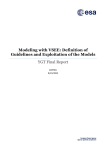
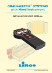
Model 300A12 High Temperature Accelerometer System Installation and Operating Manual For assistance with the operation of this product, contact PCB Piezotronics, Inc. Toll-free: 800-828-8840 24-hour SensorLine: 716-684-0001 Fax: 716-684-0987 E-mail: [email protected] Web: www.pcb.com Warranty, Service, Repair, and Return Policies and Instructions The information contained in this document supersedes all similar information that may be found elsewhere in this manual. Total Customer Satisfaction – PCB Piezotronics guarantees Total Customer Satisfaction. If, at any time, for any reason, you are not completely satisfied with any PCB product, PCB will repair, replace, or exchange it at no charge. You may also choose to have your purchase price refunded in lieu of the repair, replacement, or exchange of the product. Service – Due to the sophisticated nature of the sensors and associated instrumentation provided by PCB Piezotronics, user servicing or repair is not recommended and, if attempted, may void the factory warranty. Routine maintenance, such as the cleaning of electrical connectors, housings, and mounting surfaces with solutions and techniques that will not harm the physical material of construction, is acceptable. Caution should be observed to insure that liquids are not permitted to migrate into devices that are not hermetically sealed. Such devices should only be wiped with a dampened cloth and never submerged or have liquids poured upon them. Repair – In the event that equipment becomes damaged or ceases to operate, arrangements should be made to return the equipment to PCB Piezotronics for repair. User servicing or repair is not recommended and, if attempted, may void the factory warranty. Calibration – Routine calibration of sensors and associated instrumentation is recommended as this helps build confidence in measurement accuracy and acquired data. Equipment calibration cycles are typically established by the users own quality regimen. When in doubt about a calibration cycle, a good “rule of thumb” is to recalibrate on an annual basis. It is also good practice to recalibrate after exposure to any severe temperature extreme, shock, load, or other environmental influence, or prior to any critical test. PCB Piezotronics maintains an ISO9001 certified metrology laboratory and offers calibration services, which are accredited by A2LA to ISO/IEC 17025, with full traceablility to N.I.S.T. In addition to the normally supplied calibration, special testing is also available, such as: sensitivity at elevated or cryogenic temperatures, phase response, extended high or low frequency response, extended range, leak testing, hydrostatic pressure testing, and others. For information on standard recalibration services or special testing, contact your local PCB Piezotronics distributor, sales representative, or factory customer service representative. Returning Equipment – Following these procedures will insure that your returned materials are handled in the most expedient manner. Before returning any equipment to PCB Piezotronics, contact your local distributor, sales representative, or factory customer service representative to obtain a Return Materials Authorization (RMA) Number. This RMA number should be clearly marked on the outside of all package(s) and on the packing list(s) accompanying the shipment. A detailed account of the nature of the problem(s) being experienced with the equipment should also be included inside the package(s) containing any returned materials. PCB for a complete statement of our warranty. Expendable items, such as batteries and mounting hardware, are not covered by warranty. Mechanical damage to equipment due to improper use is not covered by warranty. Electronic circuitry failure caused by the introduction of unregulated or improper excitation power or electrostatic discharge is not covered by warranty. A Purchase Order, included with the returned materials, will expedite the turn-around of serviced equipment. It is recommended to include authorization on the Purchase Order for PCB to proceed with any repairs, as long as they do not exceed 50% of the replacement cost of the returned item(s). PCB will provide a price quotation or replacement recommendation for any item whose repair costs would exceed 50% of replacement cost, or any item that is not economically feasible to repair. For routine calibration services, the Purchase Order should include authorization to proceed and return at current pricing, which can be obtained from a factory customer service representative. Contact Information – International customers should direct all inquiries to their local distributor or sales office. A complete list of distributors and offices can be found at www.pcb.com. Customers within the United States may contact their local sales representative or a factory customer service representative. A complete list of sales representatives can be found at www.pcb.com. Toll-free telephone numbers for a factory customer service representative, in the division responsible for this product, can be found on the title page at the front of this manual. Our ship to address and general contact numbers are: Warranty – All equipment and repair services provided by PCB Piezotronics, Inc. are covered by a limited warranty against defective material and workmanship for a period of one year from date of original purchase. Contact DOCUMENT NUMBER: 21354 DOCUMENT REVISION: B ECN: 17900 PCB Piezotronics, Inc. 3425 Walden Ave. Depew, NY 14043 USA Toll-free: (800) 828-8840 24-hour SensorLineSM: (716) 684-0001 Website: www.pcb.com E-mail: [email protected] 081-XXXX-90 4 3 2 1 PCB Piezotronics Inc. claims proprietary rights in the information disclosed hereon. Neither it nor any reproduction thereof will be disclosed to others without the written consent of PCB Piezotronics Inc. REVISIONS STANDARD STUD MOUNT "B" M3 X 0.50 MOUNTING INSTRUCTIONS "A" 5-40 MOUNTING INSTRUCTIONS SENSOR 2 DESCRIPTION DIN P UPDATE DRAWING 25686 "D" M5 X 0.80 MOUNTING INSTRUCTIONS "C" 10-32 MOUNTING INSTRUCTIONS (ENGLISH DIMENSIONS IN BRACKETS) (METRIC DIMENSIONS IN BRACKETS) REV (ENGLISH DIMENSIONS IN BRACKETS) (METRIC DIMENSIONS IN BRACKETS) 2 2 2 B B SENSOR THREAD "A" SENSOR SENSOR THREAD "X" THREAD MOUNTING "X" THREAD MOUNTING MOUNTING THREAD 5-40 M3 X 0.50 10-32 M5 X 0.80 1/4-28 M6 X 1.00 INTEGRAL STUD MOUNT SEE DRAWING A B C D E F THREAD 1 .101[2.57] X .20[5.1] MIN. 5-40 UNC-2B M3 X 0.50-6H X .15[3.8] MIN. X 3.3[.13] MIN. [45-55 NEWTON CENTIMETERS]. "THRU-BOLT" STUD MOUNT "THRU-BOLT" X 7.62 [.300] MIN. 10-32 UNF-2B M5 X 0.8-6H X .15[3.8] MIN. X 5.08[.200] MIN. 10-20 INCH POUNDS [4-5 INCH POUNDS]. [113-225 NEWTON CENTIMETERS]. "F" M6 X 0.75, M6 X 1.00, M8 X 1.25 MOUNTING INSTRUCTIONS (METRIC DIMENSIONS IN BRACKETS) (ENGLISH DIMENSIONS IN BRACKETS) 4.) RECOMMENDED MOUNTING TORQUE, 2 113-225 NEWTON CENTIMETERS [10-20 INCH POUNDS]. "G" MOUNTING INSTRUCTIONS FOR SPECIAL THREAD LENGTHS (METRIC DIMENSIONS IN BRACKETS) 2 SENSOR 2 4.22[.166] X .23[5.8] MIN. 45-55 NEWTON CENTIMETERS "E" 1/4-28 MOUNTING INSTRUCTIONS SENSOR 1 4.) RECOMMENDED MOUNTING TORQUE, 4.) RECOMMENDED MOUNTING TORQUE, 4-5 INCH POUNDS MOUNTING HOLE PREPARATION: .159[4.04] 1 2.5[.099] X 4.6 [1.8] MIN. 4.) RECOMMENDED MOUNTING TORQUE, MOUNTING HOLE PREPARATION: MOUNTING HOLE PREPARATION: MOUNTING HOLE PREPARATION: 1 M6 X 0.75 MOUNTING HOLE PREPARATION: 1 "B" "C" 5.31[.209] X 7.62 [.300] MIN. M6 X 0.75-6H "X" INTEGRAL MOUNTING MOUNTING HOLE PREPARATION: "A" STUD A X 5.08[.200] MIN. "X" "A" MOUNTNG THREAD SEE DRAWING 5-40 A M3 X 0.50 B 10-32 C M5 X 0.80 D 1/4-28 E M6 X 1.00 F BOLT THREAD SEE DRAWING 10-32 C M5 X 0.80 D 1/4-28 E M6 X 1.00 F M8 X 1.25 F 1 X .300[7.62] MIN. 1/4-28 UNF-2B X .200[5.08] MIN. 4.) RECOMMENDED MOUNTING TORQUE, 1 5.05[.199] 1 6.75[.266] X 8.10 [.320] MIN. X 8.64 [.340] MIN. M6X 1.0-6H M8 X 1.25-6H X 6.35[.250] MIN. X 5.00[.197] MIN. 1 FOR BEST RESULTS, PLACE A THIN LAYER OF SILICONE GREASE (OR EQUIVALENT) ON INTERFACE PRIOR TO MOUNTING. 63[1.61] MOUNTING SURFACE SHOULD BE FLAT TO WITHIN .001(0.03) TIR OVER DIM 'A' WITH A OR BETTER FINISH FOR BEST RESULTS. DRILL PERPENDICULAR TO MOUNTING SURFACE TO WITHIN 1. 4 TAP X "B" MIN. 3 DECIMALS XX ±.01 XXX ±.005 A THREAD DEPTH : B= X + 1 THREAD PITCH DRILL DEPTH : C= B + 3 THREAD PITCH SEE A-F FOR APPROPRIATE DRILL AND TAP 3-7 NEWTON METERS [2-5 FT POUNDS]. [3-7 NEWTON METERS]. DRILL DIA. X "C" MIN. 1 THREAD PITCH SHOWN THREAD PITCH= 1/TPI [P] UNLESS OTHERWISE SPECIFIED TOLERANCES ARE: 2 1 4.) RECOMMENDED MOUNTING TORQUE, 2-5 FOOT POUNDS DIMENSIONS IN INCHES 3.) MOUNTING HOLE PREPARATION: M8 X 1.25 MOUNTING HOLE PREPARATION: M6 X 1.0 MOUNTING HOLE PREPARATION: .218[5.54] "P" DIMENSIONS IN MILLIMETERS [ IN BRACKETS ] DECIMALS X XX ± 0.3 ± 0.13 ANGLES 2 DEGREES ANGLES 2 DEGREES FILLETS AND RADII .003 - .005 FILLETS AND RADII 0.07 - 0.13 2 DRAWN JDM CHECKED 3/9/07 ECB 3/9/07 ENGINEER JJD TITLE INSTALLATION DRAWING FOR STANDARD 081 SERIES MOUNTING 3/9/07 3425 WALDEN AVE. DEPEW, NY 14043 (716) 684-0001 E-MAIL: [email protected] DWG. NO. CODE IDENT. NO. 081-XXXX-90 52681 SCALE: N.T.S. 1 SHEET 1 OF 1 Model 357M50 Shear Charge Output Accelerometer Installation and Operating Manual For assistance with the operation of this product, contact PCB Piezotronics, Inc. Toll-free: 800-828-8840 24-hour SensorLine: 716-684-0001 Fax: 716-684-0987 E-mail: [email protected] Web: www.pcb.com Warranty, Service, Repair, and Return Policies and Instructions The information contained in this document supersedes all similar information that may be found elsewhere in this manual. Total Customer Satisfaction – PCB Piezotronics guarantees Total Customer Satisfaction. If, at any time, for any reason, you are not completely satisfied with any PCB product, PCB will repair, replace, or exchange it at no charge. You may also choose to have your purchase price refunded in lieu of the repair, replacement, or exchange of the product. Service – Due to the sophisticated nature of the sensors and associated instrumentation provided by PCB Piezotronics, user servicing or repair is not recommended and, if attempted, may void the factory warranty. Routine maintenance, such as the cleaning of electrical connectors, housings, and mounting surfaces with solutions and techniques that will not harm the physical material of construction, is acceptable. Caution should be observed to insure that liquids are not permitted to migrate into devices that are not hermetically sealed. Such devices should only be wiped with a dampened cloth and never submerged or have liquids poured upon them. Repair – In the event that equipment becomes damaged or ceases to operate, arrangements should be made to return the equipment to PCB Piezotronics for repair. User servicing or repair is not recommended and, if attempted, may void the factory warranty. Calibration – Routine calibration of sensors and associated instrumentation is recommended as this helps build confidence in measurement accuracy and acquired data. Equipment calibration cycles are typically established by the users own quality regimen. When in doubt about a calibration cycle, a good “rule of thumb” is to recalibrate on an annual basis. It is also good practice to recalibrate after exposure to any severe temperature extreme, shock, load, or other environmental influence, or prior to any critical test. PCB Piezotronics maintains an ISO9001 certified metrology laboratory and offers calibration services, which are accredited by A2LA to ISO/IEC 17025, with full traceablility to N.I.S.T. In addition to the normally supplied calibration, special testing is also available, such as: sensitivity at elevated or cryogenic temperatures, phase response, extended high or low frequency response, extended range, leak testing, hydrostatic pressure testing, and others. For information on standard recalibration services or special testing, contact your local PCB Piezotronics distributor, sales representative, or factory customer service representative. Returning Equipment – Following these procedures will insure that your returned materials are handled in the most expedient manner. Before returning any equipment to PCB Piezotronics, contact your local distributor, sales representative, or factory customer service representative to obtain a Return Materials Authorization (RMA) Number. This RMA number should be clearly marked on the outside of all package(s) and on the packing list(s) accompanying the shipment. A detailed account of the nature of the problem(s) being experienced with the equipment should also be included inside the package(s) containing any returned materials. PCB for a complete statement of our warranty. Expendable items, such as batteries and mounting hardware, are not covered by warranty. Mechanical damage to equipment due to improper use is not covered by warranty. Electronic circuitry failure caused by the introduction of unregulated or improper excitation power or electrostatic discharge is not covered by warranty. A Purchase Order, included with the returned materials, will expedite the turn-around of serviced equipment. It is recommended to include authorization on the Purchase Order for PCB to proceed with any repairs, as long as they do not exceed 50% of the replacement cost of the returned item(s). PCB will provide a price quotation or replacement recommendation for any item whose repair costs would exceed 50% of replacement cost, or any item that is not economically feasible to repair. For routine calibration services, the Purchase Order should include authorization to proceed and return at current pricing, which can be obtained from a factory customer service representative. Contact Information – International customers should direct all inquiries to their local distributor or sales office. A complete list of distributors and offices can be found at www.pcb.com. Customers within the United States may contact their local sales representative or a factory customer service representative. A complete list of sales representatives can be found at www.pcb.com. Toll-free telephone numbers for a factory customer service representative, in the division responsible for this product, can be found on the title page at the front of this manual. Our ship to address and general contact numbers are: Warranty – All equipment and repair services provided by PCB Piezotronics, Inc. are covered by a limited warranty against defective material and workmanship for a period of one year from date of original purchase. Contact DOCUMENT NUMBER: 21354 DOCUMENT REVISION: B ECN: 17900 PCB Piezotronics, Inc. 3425 Walden Ave. Depew, NY 14043 USA Toll-free: (800) 828-8840 24-hour SensorLineSM: (716) 684-0001 Website: www.pcb.com E-mail: [email protected] Model Number 357M50 Revision: D SHEAR CHARGE OUTPUT ACCELEROMETER ECN #: 40410 Performance ENGLISH SI OPTIONAL VERSIONS Sensitivity(± 15 %) Measurement Range Frequency Range(+5 %) Resonant Frequency Non-Linearity Transverse Sensitivity 0.4 pC/g ± 500 g pk 10 kHz ≥ 60 kHz ≤1% ≤5% 0.04 pC/(m/s²) ± 4905 m/s² pk 10 kHz ≥ 60 kHz ≤1% ≤5% Optional versions have identical specifications and accessories as listed for the standard model except where noted below. More than one option may be used. ± 3000 g pk -100 to 500 °F ± 29,430 m/s² pk -73 to 260 °C 165 pF >108 Ohm >1011 Ohm Negative 165 pF >108 Ohm >1011 Ohm Negative [2] [3] [4] Environmental Overload Limit(Shock) Temperature Range NOTES: Electrical Capacitance Insulation Resistance(at 500°F [260°C]) Insulation Resistance(at 70° F [21°C]) Output Polarity [1] [1] [2] [3] [4] Typical. Low frequency response is determined by external signal conditioning electronics. Zero-based, least-squares, straight line method. Transverse sensitivity is typically ≤ 3%. Physical Sensing Element Ceramic Ceramic Sensing Geometry Shear Shear Housing Material Stainless Steel Stainless Steel Sealing Hermetic Hermetic Size (Hex x Height) 0.38 in x 0.87 in 9.5 mm x 22 mm Weight 0.192 oz 5.4 gm Electrical Connector 10-32 Coaxial Jack 10-32 Coaxial Jack Electrical Connection Position Top Top Mounting Thread 10-32 Male 10-32 Male Mounting Torque 10 to 20 in-lb 113 to 225 N-cm All specifications are at room temperature unless otherwise specified. In the interest of constant product improvement, we reserve the right to change specifications without notice. ICP® is a registered trademark of PCB Group, Inc. SUPPLIED ACCESSORIES: Model ACS-1 NIST traceable frequency response (10 Hz to upper 5% point). (1) [1] Entered: AP Engineer: MAM Sales: WDC Approved: BAM Spec Number: Date: 1/30/2013 Date: 1/30/2013 Date: 1/30/2013 Date: 1/30/2013 16938 3425 Walden Avenue, Depew, NY 14043 Phone: 716-684-0001 Fax: 716-684-0987 E-Mail: [email protected] 081-XXXX-90 4 3 2 1 PCB Piezotronics Inc. claims proprietary rights in the information disclosed hereon. Neither it nor any reproduction thereof will be disclosed to others without the written consent of PCB Piezotronics Inc. REVISIONS STANDARD STUD MOUNT "B" M3 X 0.50 MOUNTING INSTRUCTIONS "A" 5-40 MOUNTING INSTRUCTIONS SENSOR 2 DESCRIPTION DIN P UPDATE DRAWING 25686 "D" M5 X 0.80 MOUNTING INSTRUCTIONS "C" 10-32 MOUNTING INSTRUCTIONS (ENGLISH DIMENSIONS IN BRACKETS) (METRIC DIMENSIONS IN BRACKETS) REV (ENGLISH DIMENSIONS IN BRACKETS) (METRIC DIMENSIONS IN BRACKETS) 2 2 2 B B SENSOR THREAD "A" SENSOR SENSOR THREAD "X" THREAD MOUNTING "X" THREAD MOUNTING MOUNTING THREAD 5-40 M3 X 0.50 10-32 M5 X 0.80 1/4-28 M6 X 1.00 INTEGRAL STUD MOUNT SEE DRAWING A B C D E F THREAD 1 .101[2.57] X .20[5.1] MIN. 5-40 UNC-2B M3 X 0.50-6H X .15[3.8] MIN. X 3.3[.13] MIN. [45-55 NEWTON CENTIMETERS]. "THRU-BOLT" STUD MOUNT "THRU-BOLT" X 7.62 [.300] MIN. 10-32 UNF-2B M5 X 0.8-6H X .15[3.8] MIN. X 5.08[.200] MIN. 10-20 INCH POUNDS [4-5 INCH POUNDS]. [113-225 NEWTON CENTIMETERS]. "F" M6 X 0.75, M6 X 1.00, M8 X 1.25 MOUNTING INSTRUCTIONS (METRIC DIMENSIONS IN BRACKETS) (ENGLISH DIMENSIONS IN BRACKETS) 4.) RECOMMENDED MOUNTING TORQUE, 2 113-225 NEWTON CENTIMETERS [10-20 INCH POUNDS]. "G" MOUNTING INSTRUCTIONS FOR SPECIAL THREAD LENGTHS (METRIC DIMENSIONS IN BRACKETS) 2 SENSOR 2 4.22[.166] X .23[5.8] MIN. 45-55 NEWTON CENTIMETERS "E" 1/4-28 MOUNTING INSTRUCTIONS SENSOR 1 4.) RECOMMENDED MOUNTING TORQUE, 4.) RECOMMENDED MOUNTING TORQUE, 4-5 INCH POUNDS MOUNTING HOLE PREPARATION: .159[4.04] 1 2.5[.099] X 4.6 [1.8] MIN. 4.) RECOMMENDED MOUNTING TORQUE, MOUNTING HOLE PREPARATION: MOUNTING HOLE PREPARATION: MOUNTING HOLE PREPARATION: 1 M6 X 0.75 MOUNTING HOLE PREPARATION: 1 "B" "C" 5.31[.209] X 7.62 [.300] MIN. M6 X 0.75-6H "X" INTEGRAL MOUNTING MOUNTING HOLE PREPARATION: "A" STUD A X 5.08[.200] MIN. "X" "A" MOUNTNG THREAD SEE DRAWING 5-40 A M3 X 0.50 B 10-32 C M5 X 0.80 D 1/4-28 E M6 X 1.00 F BOLT THREAD SEE DRAWING 10-32 C M5 X 0.80 D 1/4-28 E M6 X 1.00 F M8 X 1.25 F 1 X .300[7.62] MIN. 1/4-28 UNF-2B X .200[5.08] MIN. 4.) RECOMMENDED MOUNTING TORQUE, 1 5.05[.199] 1 6.75[.266] X 8.10 [.320] MIN. X 8.64 [.340] MIN. M6X 1.0-6H M8 X 1.25-6H X 6.35[.250] MIN. X 5.00[.197] MIN. 1 FOR BEST RESULTS, PLACE A THIN LAYER OF SILICONE GREASE (OR EQUIVALENT) ON INTERFACE PRIOR TO MOUNTING. 63[1.61] MOUNTING SURFACE SHOULD BE FLAT TO WITHIN .001(0.03) TIR OVER DIM 'A' WITH A OR BETTER FINISH FOR BEST RESULTS. DRILL PERPENDICULAR TO MOUNTING SURFACE TO WITHIN 1. 4 TAP X "B" MIN. 3 DECIMALS XX ±.01 XXX ±.005 A THREAD DEPTH : B= X + 1 THREAD PITCH DRILL DEPTH : C= B + 3 THREAD PITCH SEE A-F FOR APPROPRIATE DRILL AND TAP 3-7 NEWTON METERS [2-5 FT POUNDS]. [3-7 NEWTON METERS]. DRILL DIA. X "C" MIN. 1 THREAD PITCH SHOWN THREAD PITCH= 1/TPI [P] UNLESS OTHERWISE SPECIFIED TOLERANCES ARE: 2 1 4.) RECOMMENDED MOUNTING TORQUE, 2-5 FOOT POUNDS DIMENSIONS IN INCHES 3.) MOUNTING HOLE PREPARATION: M8 X 1.25 MOUNTING HOLE PREPARATION: M6 X 1.0 MOUNTING HOLE PREPARATION: .218[5.54] "P" DIMENSIONS IN MILLIMETERS [ IN BRACKETS ] DECIMALS X XX ± 0.3 ± 0.13 ANGLES 2 DEGREES ANGLES 2 DEGREES FILLETS AND RADII .003 - .005 FILLETS AND RADII 0.07 - 0.13 2 DRAWN JDM CHECKED 3/9/07 ECB 3/9/07 ENGINEER JJD TITLE INSTALLATION DRAWING FOR STANDARD 081 SERIES MOUNTING 3/9/07 3425 WALDEN AVE. DEPEW, NY 14043 (716) 684-0001 E-MAIL: [email protected] DWG. NO. CODE IDENT. NO. 081-XXXX-90 52681 SCALE: N.T.S. 1 SHEET 1 OF 1 Model 422M136 In-Line Charge Converter Installation and Operating Manual For assistance with the operation of this product, contact PCB Piezotronics, Inc. Toll-free: 800-828-8840 24-hour SensorLine: 716-684-0001 Fax: 716-684-0987 E-mail: [email protected] Web: www.pcb.com Warranty, Service, Repair, and Return Policies and Instructions The information contained in this document supersedes all similar information that may be found elsewhere in this manual. Total Customer Satisfaction – PCB Piezotronics guarantees Total Customer Satisfaction. If, at any time, for any reason, you are not completely satisfied with any PCB product, PCB will repair, replace, or exchange it at no charge. You may also choose to have your purchase price refunded in lieu of the repair, replacement, or exchange of the product. Service – Due to the sophisticated nature of the sensors and associated instrumentation provided by PCB Piezotronics, user servicing or repair is not recommended and, if attempted, may void the factory warranty. Routine maintenance, such as the cleaning of electrical connectors, housings, and mounting surfaces with solutions and techniques that will not harm the physical material of construction, is acceptable. Caution should be observed to insure that liquids are not permitted to migrate into devices that are not hermetically sealed. Such devices should only be wiped with a dampened cloth and never submerged or have liquids poured upon them. Repair – In the event that equipment becomes damaged or ceases to operate, arrangements should be made to return the equipment to PCB Piezotronics for repair. User servicing or repair is not recommended and, if attempted, may void the factory warranty. Calibration – Routine calibration of sensors and associated instrumentation is recommended as this helps build confidence in measurement accuracy and acquired data. Equipment calibration cycles are typically established by the users own quality regimen. When in doubt about a calibration cycle, a good “rule of thumb” is to recalibrate on an annual basis. It is also good practice to recalibrate after exposure to any severe temperature extreme, shock, load, or other environmental influence, or prior to any critical test. PCB Piezotronics maintains an ISO9001 certified metrology laboratory and offers calibration services, which are accredited by A2LA to ISO/IEC 17025, with full traceablility to N.I.S.T. In addition to the normally supplied calibration, special testing is also available, such as: sensitivity at elevated or cryogenic temperatures, phase response, extended high or low frequency response, extended range, leak testing, hydrostatic pressure testing, and others. For information on standard recalibration services or special testing, contact your local PCB Piezotronics distributor, sales representative, or factory customer service representative. Returning Equipment – Following these procedures will insure that your returned materials are handled in the most expedient manner. Before returning any equipment to PCB Piezotronics, contact your local distributor, sales representative, or factory customer service representative to obtain a Return Materials Authorization (RMA) Number. This RMA number should be clearly marked on the outside of all package(s) and on the packing list(s) accompanying the shipment. A detailed account of the nature of the problem(s) being experienced with the equipment should also be included inside the package(s) containing any returned materials. PCB for a complete statement of our warranty. Expendable items, such as batteries and mounting hardware, are not covered by warranty. Mechanical damage to equipment due to improper use is not covered by warranty. Electronic circuitry failure caused by the introduction of unregulated or improper excitation power or electrostatic discharge is not covered by warranty. A Purchase Order, included with the returned materials, will expedite the turn-around of serviced equipment. It is recommended to include authorization on the Purchase Order for PCB to proceed with any repairs, as long as they do not exceed 50% of the replacement cost of the returned item(s). PCB will provide a price quotation or replacement recommendation for any item whose repair costs would exceed 50% of replacement cost, or any item that is not economically feasible to repair. For routine calibration services, the Purchase Order should include authorization to proceed and return at current pricing, which can be obtained from a factory customer service representative. Contact Information – International customers should direct all inquiries to their local distributor or sales office. A complete list of distributors and offices can be found at www.pcb.com. Customers within the United States may contact their local sales representative or a factory customer service representative. A complete list of sales representatives can be found at www.pcb.com. Toll-free telephone numbers for a factory customer service representative, in the division responsible for this product, can be found on the title page at the front of this manual. Our ship to address and general contact numbers are: Warranty – All equipment and repair services provided by PCB Piezotronics, Inc. are covered by a limited warranty against defective material and workmanship for a period of one year from date of original purchase. Contact DOCUMENT NUMBER: 21354 DOCUMENT REVISION: B ECN: 17900 PCB Piezotronics, Inc. 3425 Walden Ave. Depew, NY 14043 USA Toll-free: (800) 828-8840 24-hour SensorLineSM: (716) 684-0001 Website: www.pcb.com E-mail: [email protected] The Model 422E In-Line Charge Converter Operating Guide with Enclosed Warranty Information 3425 Walden Avenue, Depew, New York 14043-2495 Phone 716 684-0001 Fax 716 684-0987 E-Mail [email protected] Toll Free Line 1-800-828-8840 24 Hour Sensor Line 716 684-0001 MANUAL NUMBER: 18882 MANUAL REVISION: A ECN: 24741 ACCELERATION • ACOUSTICS • ACTUATION • FORCE • LOAD • PRESSURE • SHOCK • STRAIN • TORQUE • VIBRATION Total Customer Satisfaction Guarantee table of contents Introduction....................................................................................................................... page 3 Description ....................................................................................................................... page 3 Installation ........................................................................................................................ page 3 Operation.......................................................................................................................... page 3 Calculation of Output Scaling ........................................................................................... page 4 TEDS Functionality........................................................................................................... page 4 Special Considerations..................................................................................................... page 5 422E Series Models for Use with High Temperature Sensors.......................................... page 5 422E Series Models for Use in Radioactive Environments............................................... page 6 ESD Warning Information................................................................................................. page 6 warranty/servicing Warranty, Service & Return Procedure ............................................................................ page 7 Customer Service............................................................................................................. page 8 PAGE 2 ACCELERATION • ACOUSTICS • ACTUATION • FORCE • LOAD • PRESSURE • SHOCK • STRAIN • TORQUE • VIBRATION Total Customer Satisfaction Guarantee introduction The 422E series in-line charge converters are designed to convert the high impedance of a charge mode piezoelectric transducer to a low-impedance voltage by means of an ICP ® signal conditioner. These units may be used with either quartz or ceramic charge-mode piezoelectric sensors. description The 422E series in-line charge amplifiers operate from an ICP ® signal conditioner. The unit employs a high gain amplifier to perform the impedance transformation. The charge output of the transducers may be scaled in terms of acceleration, pressure or force. The output is then mV/g, mV/psi or mV/lb, respectively. installation Connect the 422E series to the transducer with low-noise cable (003A) only. Standard coaxial or twowire cable may be used between the amplifier and the signal conditioner, and between the signal conditioner and the readout device. Note: For optimum noise performance, the cable length between the sensor and the 422E should be minimized. operation To operate, simply connect the input of the 422E to the transducer using low-noise (003A) cable and the output to any ICP ® signal conditioner using standard cable. The output of the signal conditioner may then be connected to an oscilloscope or other monitoring device. This output will be an AC signal (see specification for actual frequency response) with a DC bias. Many PCB signal conditioners remove the bias via an AC coupling circuit. PAGE 3 ACCELERATION • ACOUSTICS • ACTUATION • FORCE • LOAD • PRESSURE • SHOCK • STRAIN • TORQUE • VIBRATION Total Customer Satisfaction Guarantee calculation of output scaling The 422E contains a high-gain, low-noise amplifier connected in a charge amplifier configuration. The charge output of the transducer is transferred to the feedback capacitor of the amplifier to develop a voltage which may be calculated using the following equation. Vout = 422E Scaling (mV/pC) x Transducer Sensitivity (pC/Engineering Unit) where: Vout = Output of 422E in mV/Engineering Unit the Engineering Unit may be g’s, Newtons, psi, etc., depending on the sensor Example: A 357A12 (3 pC/g) is used with a 422E02 (10 mV/pC). Calculate the output in mV/g. Answer: 10 mV/pC x 3 pC/g = 30 mV/g TEDS functionality 422E units with a “T” prefix incorporate TEDS (Transducer Electronic Data Sheet) technology. Using a TEDS capable signal conditioner, or TEDS reader, the user is able to read calibration data stored in the sensor. Some systems allow the user to also write user data and calibration information to the 422E. All data is formatted in accordance with IEEE 1451.4. PAGE 4 ACCELERATION • ACOUSTICS • ACTUATION • FORCE • LOAD • PRESSURE • SHOCK • STRAIN • TORQUE • VIBRATION Total Customer Satisfaction Guarantee special considerations High source capacitance may degrade the performance of the 422E (source capacitance is the input capacitance defined as transducer capacitance + cable capacitance). In particular, noise may increase and high frequency response may decrease if source capacitance exceeds the recommended level. In some cases, low frequency oscillation of the output may occur. The maximum recommended level in pF’s is determined using the following formula: maximum recommended source capacitance = 10,000/422E sensitivity in mV/pC For example, the level for a 422E02/E12 would be 10,000/10 pF = 1,000 pF, and the level for a 422E03/E13 would be 10,000 pF. If PCB 003 type low noise cable is used, these values correspond to 10 meters and 100 meters of length respectively. 422E series models for use with high temperature sensors The 422E35 (1 mV/pC) and 422E36 (10 mV/pC) have been specifically designed to operate with the lower insulation resistance values which piezoelectric sensors may exhibit when subjected to very high temperatures (generally greater than 500° F). Both units will operate with insulation resistances as low as 10kΩ. Note: Because of the special circuitry required, the 422E35 and 422E36 have somewhat higher noise and longer turn on time than the equivalent units designed for use with sensors with high insulation resistance (the 422E03 and 422E02 respectively). Consult the specifications for details. Caution! Excessive accumulated charges on the input cables can destroy the field effect transistor (FET) in the amplifier. These charges can be grounded by shorting the center pin on the cable connector plug to its knurled nut with any metallic object. PAGE 5 ACCELERATION • ACOUSTICS • ACTUATION • FORCE • LOAD • PRESSURE • SHOCK • STRAIN • TORQUE • VIBRATION Total Customer Satisfaction Guarantee 422E series models for use in radioactive environments The 422E65 (1mV/pC) and 422E66 (10mV/pC) were designed to offer resistance to the effects of radiation exposure up to 1 Mrad Integrated Gamma Flux or 1010 N/cm2 of Integrated Neutron Flux. They are also designed to operate with lower insulation values which piezoelectric sensors may exhibit when subjected to the high temperatures that generally accompany high levels of radioactivity. warning 1 – ESD sensitivity The power supply/signal conditioner should not be opened by anyone other than qualified service personnel. This product is intended for use by qualified personnel who recognize shock hazards and are familiar with the safety precautions required to avoid injury. warning 2 – ESD sensitivity This equipment is designed with user safety in mind; however, the protection provided by the equipment may be impaired if the equipment is used in a manner not specified by PCB Piezotronics, Inc. caution 1 – ESD sensitivity Cables can kill your equipment. High voltage electrostatic discharge (ESD) can damage electrical devices. Similar to a capacitor, a cable can hold a charge caused by triboelectric transfer, such as that which occurs in the following: • Laying on and moving across a rug, • Any movement through air, • The action of rolling out a cable, and/or • Contact with a non-grounded person. The PCB solution for product safety: • Connect the cables only with the AC power off. • Temporarily “short” the end of the cable before attaching it to any signal input or output. PAGE 6 ACCELERATION • ACOUSTICS • ACTUATION • FORCE • LOAD • PRESSURE • SHOCK • STRAIN • TORQUE • VIBRATION Total Customer Satisfaction Guarantee caution 2 – ESD sensitivity ESD considerations should be made prior to performing any internal adjustments on the equipment. Any piece of electronic equipment is vulnerable to ESD when opened for adjustments. Internal adjustments should therefore be done ONLY at an ESD-safe work area. Many products have ESD protection, but the level of protection may be exceeded by extremely high voltage. warranty PCB instrumentation is warranted against defective material and workmanship for 1 year unless otherwise expressly specified. Damage to instruments caused by incorrect power or misapplication, is not covered by warranty. If there are any questions regarding power, intended application, or general usage, please consult with your local sales contact or distributor. Batteries and other expendable hardware items are not covered by warranty. service Because of the sophisticated nature of PCB instrumentation, field repair is typically NOT recommended and may void any warranty. If factory service is required, return the instrumentation according to the “Return Procedure” stated below. A repair and/or replacement quotation will be provided prior to servicing at no charge. Before returning the unit, please consult a factory PCB applications engineer concerning the situation as certain problems can often be corrected with simple on-site procedures. return procedure To expedite returned instrumentation, contact a factory PCB applications engineer for a RETURN MATERIAL AUTHORIZATION (RMA) NUMBER. Please have information available such as model and serial number. Also, to insure efficient service, provide a written description of the symptoms and problems with the equipment to a local sales representative or distributor, or contact PCB if none are located in your area. PAGE 7 ACCELERATION • ACOUSTICS • ACTUATION • FORCE • LOAD • PRESSURE • SHOCK • STRAIN • TORQUE • VIBRATION Total Customer Satisfaction Guarantee Customers outside the U.S. should consult their local PCB distributor for information on returning equipment. For exceptions, please contact the International Sales department at PCB to request shipping instructions and an RMA. For assistance, please call (716) 684-0003, or fax us at (716) 6843823. You may also receive assistance via e-mail at [email protected] or visit our web site at www.pcb.com. customer service PCB guarantees Total Customer Satisfaction. If, at any time, for any reason, you are not completely satisfied with any PCB product, PCB will repair, replace, or exchange it at no charge. You may also choose, within the warranty period, to have your purchase price refunded. PCB offers to all customers, at no charge, 24-hour phone support. This service makes product or application support available to our customers, day or night, seven days a week. When unforeseen problems or emergency situations arise, call the 24 Hour SensorLine at 716 684-0001, and an application specialist will assist you. 3425 Walden Avenue, Depew, NY 14043-2495 Phone 716 684-0001 Fax 716 684-0987 E-Mail [email protected] PCB www.PCB.com IMI www.IMI-Sensors.com Key www.KeyTransducers.com ISO 9001 Certified © 2001 PCB Group, Inc. In the interest of constant product improvement, specifications are subject to change without notice. All prices are subject to change without notice. PCB, ICP and Modally Tuned are registered trademarks of PCB Group, Inc. TORKDISC is a trademark of Key Transducers, Inc. Swiveler and Spindler are trademarks of PCB Group, Inc. IMI, SensorLine and Sensors that measure up! are service marks of PCB Group, Inc. All other trademarks are properties of their respective owners. PAGE 8 ACCELERATION • ACOUSTICS • ACTUATION • FORCE • LOAD • PRESSURE • SHOCK • STRAIN • TORQUE • VIBRATION Total Customer Satisfaction Guarantee