1
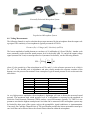
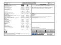
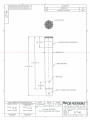
Model 378B02 ICP Microphone System Installation and Operating Manual This manual contains the 377B02, 426E01 installation and operating manuals that comprise a Model 378B02 ICP Microphone System kit. For assistance with the operation of this product, contact PCB Piezotronics, Inc. Toll-free: 800-828-8840 24-hour SensorLine: 716-684-0001 Fax: 716-684-0987 E-mail: [email protected] Web: www.pcb.com Warranty, Service, Repair, and Return Policies and Instructions The information contained in this document supersedes all similar information that may be found elsewhere in this manual. Total Customer Satisfaction – PCB Piezotronics guarantees Total Customer Satisfaction. If, at any time, for any reason, you are not completely satisfied with any PCB product, PCB will repair, replace, or exchange it at no charge. You may also choose to have your purchase price refunded in lieu of the repair, replacement, or exchange of the product. Service – Due to the sophisticated nature of the sensors and associated instrumentation provided by PCB Piezotronics, user servicing or repair is not recommended and, if attempted, may void the factory warranty. Routine maintenance, such as the cleaning of electrical connectors, housings, and mounting surfaces with solutions and techniques that will not harm the physical material of construction, is acceptable. Caution should be observed to insure that liquids are not permitted to migrate into devices that are not hermetically sealed. Such devices should only be wiped with a dampened cloth and never submerged or have liquids poured upon them. Repair – In the event that equipment becomes damaged or ceases to operate, arrangements should be made to return the equipment to PCB Piezotronics for repair. User servicing or repair is not recommended and, if attempted, may void the factory warranty. Calibration – Routine calibration of sensors and associated instrumentation is recommended as this helps build confidence in measurement accuracy and acquired data. Equipment calibration cycles are typically established by the users own quality regimen. When in doubt about a calibration cycle, a good “rule of thumb” is to recalibrate on an annual basis. It is also good practice to recalibrate after exposure to any severe temperature extreme, shock, load, or other environmental influence, or prior to any critical test. PCB Piezotronics maintains an ISO9001 certified metrology laboratory and offers calibration services, which are accredited by A2LA to ISO/IEC 17025, with full traceablility to N.I.S.T. In addition to the normally supplied calibration, special testing is also available, such as: sensitivity at elevated or cryogenic temperatures, phase response, extended high or low frequency response, extended range, leak testing, hydrostatic pressure testing, and others. For information on standard recalibration services or special testing, contact your local PCB Piezotronics distributor, sales representative, or factory customer service representative. Returning Equipment – Following these procedures will insure that your returned materials are handled in the most expedient manner. Before returning any equipment to PCB Piezotronics, contact your local distributor, sales representative, or factory customer service representative to obtain a Return Materials Authorization (RMA) Number. This RMA number should be clearly marked on the outside of all package(s) and on the packing list(s) accompanying the shipment. A detailed account of the nature of the problem(s) being experienced with the equipment should also be included inside the package(s) containing any returned materials. PCB for a complete statement of our warranty. Expendable items, such as batteries and mounting hardware, are not covered by warranty. Mechanical damage to equipment due to improper use is not covered by warranty. Electronic circuitry failure caused by the introduction of unregulated or improper excitation power or electrostatic discharge is not covered by warranty. A Purchase Order, included with the returned materials, will expedite the turn-around of serviced equipment. It is recommended to include authorization on the Purchase Order for PCB to proceed with any repairs, as long as they do not exceed 50% of the replacement cost of the returned item(s). PCB will provide a price quotation or replacement recommendation for any item whose repair costs would exceed 50% of replacement cost, or any item that is not economically feasible to repair. For routine calibration services, the Purchase Order should include authorization to proceed and return at current pricing, which can be obtained from a factory customer service representative. Contact Information – International customers should direct all inquiries to their local distributor or sales office. A complete list of distributors and offices can be found at www.pcb.com. Customers within the United States may contact their local sales representative or a factory customer service representative. A complete list of sales representatives can be found at www.pcb.com. Toll-free telephone numbers for a factory customer service representative, in the division responsible for this product, can be found on the title page at the front of this manual. Our ship to address and general contact numbers are: Warranty – All equipment and repair services provided by PCB Piezotronics, Inc. are covered by a limited warranty against defective material and workmanship for a period of one year from date of original purchase. Contact DOCUMENT NUMBER: 21354 DOCUMENT REVISION: B ECN: 17900 PCB Piezotronics, Inc. 3425 Walden Ave. Depew, NY 14043 USA Toll-free: (800) 828-8840 24-hour SensorLineSM: (716) 684-0001 Website: www.pcb.com E-mail: [email protected] PRODUCT GUIDE 377 SERIES MICROPHONES 426 SERIES PREAMPLIFIERS Contents: 1.0 2.0 3.0 4.0 5.0 6.0 7.0 8.0 Introduction ................................................................................ 1 Standards .................................................................................... 1 Setting up a Microphone Measurement System ........................ 1 Taking Measurements ................................................................ 2 Accessories ................................................................................. 3 Maintenance ............................................................................... 3 Calibration .................................................................................. 4 Warranty and Service ................................................................. 4 1.0 Introduction Thank you for your purchase of a PCB high quality microphone. These microphones offer highly accurate and reliable acoustic measurements and are typically used in research and design applications. They are accurate enough for laboratory usage, yet rugged enough for field-testing. Sound within the typical 20 to 20,000 Hz audible range of a healthy human ear can either be pleasing to the ear, as in music, or unpleasant (or harmful), as in noise. As a result, many applications, from the development of consumer products to research in acoustics, measure sound, even sound outside the range of human hearing. The instrument typically used to measure sound is the microphone, which is designed, like the human ear, to transform pressure oscillations into a corresponding voltage oscillation. 2.0 Standards Before selecting an acoustical instrument, it is important to identify which acoustical standards are appropriate for the application in which the instrument will be used. Whether for legal purposes or for quality assurance programs, these standards will help determine the required quality, accuracy and consistency of the instrument. Standards that correspond to the performance requirements, dimensions and characteristics of acoustical components are established for microphones, sound level meters, calibrators, or other related components. The most common organizations producing these standards are the American National Standards Institute (ANSI) and the International Electrotechnical Commission (IEC). IEC 1094-4 establishes specifications for the mechanical dimensions and certain electroacoustic characteristics for standard industrial microphones. The performance specification sheet supplied with each PCB microphone identifies the standards to which the microphone is compliant. 3.0 Setting up a Microphone Measurement System After the proper microphone has been selected, the corresponding preamplifier, cabling, power supplies, signal conditioning and data acquisition selections are ready to be installed. Not all of these components are required for all test set-ups. The figures below show typical set-ups for externally polarized and prepolarized microphone systems. A prepolarized microphone can be used with a standard Microphone Power Supply designed for externally polarized microphones, and its preamplifier, provided the supply voltage is set to zero. 1 Externally Polarized Microphone System Prepolarized Microphone System 4.0 Taking Measurements The following formula is used to calculate the pressure measured by the microphone from the output voltage signal. The sensitivity of a microphone is typically measured at 250 Hz. Pressure (Pa) = Voltage (mV) / Sensitivity (mV/Pa). The lowest amplitude a healthy human ear can detect is 20 millionths of a Pascal (20Pa). Another scale more commonly used to describe sound pressure level is the decibel (dB). To convert the output voltage signal (measured in Vrms) to sound pressure level (measured in decibels), use the following formula: V SPL 20 Log rms SP ref dB where S is the sensitivity of the microphone in mV/Pa, and Pref is the reference pressure in air, which is 20 x 10-6 Pa. The decibel scale is logarithmic and more closely matches the response reactions of the human ear to the pressure fluctuations. Some examples of typical sound pressure levels are shown in the table below. dB 0 60 80 94 100 120 140 Pressure 0.00002 Pa 0.02 Pa 0.2 Pa 1 Pa 2 Pa 20 Pa 200 Pa Example Threshold of Hearing Business Office Shop Noise Large Truck Jackhammer Airplane Take-Off Threshold of Pain At very high-pressure amplitudes, the microphone’s diaphragm will start to distort the measured sound pressure. The maximum rated sound pressure level of a microphone is expressed as the amplitude at which the Total Harmonic Distortion (THD) reaches a specified amount, typically 3% THD. It is important to note that the highest sound pressure level that can be measured with a microphone system may be limited by other parts of the system, such as the preamplifier, signal conditioner, or instrumentation. Conversely, the Cartridge Thermal Noise (CTN) specification provides the lowest measurable sound pressure level that can be detected above the electrical noise inherent within the microphone. 2 Temperature and pressure will affect the sensitivity of a microphone but these effects can be accounted for by adjusting the recorded microphone values using the coefficients specified for each microphone model. Simply calculate the difference in temperature and ambient pressure from those recorded during calibration and multiply this value by the proper coefficient to determine the sensitivity offset. In most cases, the offset will be very small and is therefore unnecessary. 5.0 Accessories Transducer Electronics Data Sheet (TEDS) Preamplifiers can incorporate TEDS devices, which have a built in read/write memory that contains relevant information about the sensor and its use. Information includes manufacturer name, model number, serial number, sensitivity, etc. The operation of TEDS devices is defined by IEEE P1451.4. A TEDS microphone system includes a microphone mated with a preamplifier that contains the TEDS memory programmed with both the microphone and preamplifier information. This is particularly helpful when using large channel count systems and array set-up. A-Weight Inline Filter The inline filter is used in conjunction with an ICP® preamplifier to provide A-weighting for acoustical measurements. The filter’s frequency response is weighted according to the A-weighting filter portion of both ANSI S1.4 and IEC 60651 Type 1 Sound Level Meter Standards. ICP® signal conditioners of 4 mA or greater are recommended when using inline filters. Windscreens and Nose cones Wind induced noise can be reduced by using a windscreen. This can offer some protection against dust particles and mechanical damage. In the presence of high-speed airflow from a well-defined direction, such as wind tunnels, a nose cone is recommended. When using windscreens and noise cones, the frequency response of the microphone will be attenuated at higher frequencies. Clamps and stands When holding a microphone in place, it is important to minimize the influence of the stand on the sound being measured. This can be accomplished by using low profile stands and clamps available from PCB. Cables and Electronics PCB carries LEMO cables as well as coaxial cables with BNC and 10-32 connectors. Traditional externally polarized microphone power supplies along with a variety of ICP® signal conditioners are available that will fit almost any need. 6.0 Maintenance Microphones are very stable over long periods of time, provided they are handled and stored properly. The microphone contains fragile components that can be damaged by misuse, in particular the diaphragm, which is made up of a very thin proprietary material and should be kept clean of dust, dirt, moisture and free any type of imperfection (scratch, dent, etc.). The microphone’s grid cap is designed to let the true sound pressure level through to the diaphragm while preventing items from coming in contact with it. We do not recommend that you ever remove the grid cap or clean the microphone. If you take the precautionary measures to keep the microphone clean and dry, it should not be necessary. Use of accessories, like windscreens, and desiccants will help keep moisture off the microphone and maintain the specified sensitivity level. Nose cones will help keep turbulence off the microphone diaphragm and allow the sound pressure to be measured with greater accuracy. Keep the microphone and preamplifier assembled while preparing for testing. Keep the rubber maintenance caps on the preamplifier’s electrical connector only. Do not place these rubber caps over the microphone. This will create a vacuum and undo pressure on the microphone diaphragm, which can stretch the diaphragm and cause a change in sensitivity. Store the microphones and preamplifiers in their protective 3 cases when not in use. With proper maintenance, the microphone and preamplifier should provide stable and accurate results for years to come. Dust, rain, oil, moisture or exposure to extreme temperatures may adversely affect the microphone and preamplifier’s performance. If the microphone or the inside of the connection area of the preamplifier becomes contaminated, use a light pressure rubber bulb to gently blow clean, dry air onto the unit in order to remove the dust. In the event that you absolutely must take off the grid cap and clean the microphone diaphragm, we recommend using a blow bulb or a light pressure, clean and dry air hose to gently blow contamination off the diaphragm. The direction of the air should be parallel with the diaphragm, not directly (0 degree incidence) pointed at the diaphragm. Do not touch the microphone’s diaphragm with your fingers or let it come in contact with any sharp or pointed object. Please note that any contact to the microphone’s diaphragm can negatively impact the sensitivity and long term stability of the microphone. If the microphone is ever dropped or comes into contact with any contamination, or is exposed to extreme temperatures, we recommend immediate recalibration of the microphone. Please note that heat from your hands can affect the calibration results. It is always good practice to wait a minimum of 30 seconds after placing the microphone on a test system before taking a calibration reading in order to minimize the effect that heat from your hands has on the calibration. 7.0 Calibration PCB offers recalibration services for our precision microphones, as well as units produced by other A2LA manufacturers. Our internal metrology laboratory is certified to ISO 9001, accredited by A2LA to ANSI/IEC 17025 and ANSI/NCSL Z540-1, complies with ISO 10012-1 (and former MIL-STD-45662A), and uses equipment directly traceable to one or more of the following National Labs (NIST, PTB or DFM). Our investment in equipment, traceability and conformance to industry standards ensures accurate calibration against relevant specifications. We also carry a line of acoustic calibrators that can be used to calibrate microphone sensitivity on site as needed. 8.0 Warranty and Service All equipment and repair services provided by PCB Piezotronics, Inc. are covered by a warranty against defective material and workmanship under a Total Customer Satisfaction policy. If, at any time, for any reason, you are not completely satisfied with any PCB product, PCB will repair, replace, or exchange it at no charge. You may also choose to have your purchase price refunded. See the supplemental sheet, contained with this manual, for information on our service, repair and return policies, procedures and instructions. When unexpected problems arise, call our 24-Hour SensorLineSM (716-684-0001) to speak with an Application Engineer. Visit www.pcb.com for a complete statement of our warranty. 24-hour SensorLineSM: 716-684-0001 U.S.A. Fax: 716-684-0987 Toll-free (in the U.S.A.): 800-828-8840 3425 Walden Avenue, Depew, NY 14043-2495 E-Mail: [email protected] Website: www.pcb.com A PCB GROUP COMPANY ISO 9001 CERTIFIED A2LA ACCREDITED to ISO 17025 2014 PCB Group, Inc. In the interest of constant product improvement, specifications are subject to change without notice. PCB and ICP are registered trademarks of PCB Group, Inc. Sensor Line is a service mark of PCB Group, Inc. All other trademarks are properties of the respective owners. Manual Number: 27042 Manual Revision: C ECO 42502 Printed in the U.S.A. 4 Model Number 378B02 Performance Nominal Microphone Diameter Frequency Response Characteristic(at 0° incidence) Open Circuit Sensitivity Open Circuit Sensitivity(+/-1.5 dB) Frequency Range(+/-1 dB) Frequency Range(+/-2 dB) Lower Limiting Frequency(-3 dB) Inherent Noise(Linear) Inherent Noise Dynamic Range(3% Distortion Limit) Dynamic Range(Maximum without Clipping) TEDS Compliant ENGLISH -40 to +176 °F 0.005 dB/°F -0.013 dB/kPa ± 0.001 dB/%RH 63 dB re 20 µPa ECN #: 42896 SI OPTIONAL VERSIONS 1/2" 1/2" Free-Field Free-Field [3] 50 mV/Pa 50 mV/Pa [3] -26 dB re 1 V/Pa -26 dB re 1 V/Pa 7 to 10,000 Hz 7 to 10,000 Hz 3.75 to 20,000 Hz 3.75 to 20,000 Hz 1.0 to 3.0 Hz 1.0 to 3.0 Hz <18.5 dB re 20 µPa <18.5 dB re 20 µPa <16.5 dB(A) re 20 <16.5 dB(A) re 20 µPa µPa >135 dB re 20 µPa >135 dB re 20 µPa 138 dB re 20 µPa 138 dB re 20 µPa [2][4] [5] Yes Yes Environmental Temperature Range(Operating) Temperature Coefficient of Sensitivity(+14 to +158°F (-10 to +70°C)) Static Pressure Coefficient Humidity Coefficient of Sensitivity(0 to 100%, non-condensing) Influence of Axial Vibration(0.1g (1 m/s²)) Revision: A ICP MICROPHONE SYSTEM -40 to +80 °C [2][3] 0.009 dB/°C [2][3] -0.013 dB/kPa [3] ± 0.001 dB/%RH [2] 63 dB re 20 µPa Optional versions have identical specifications and accessories as listed for the standard model except where noted below. More than one option may be used. TLD - TEDS Capable of Digital Memory and Communication Compliant with IEEE 1451.4 Optional Accessory : Model ACS-63 Calibration (with TEDS) of Precision Condenser Microphones and Preamplifiers together (mated pair). (1) replaces Model ACS-42 NOTES: [1] [2] [3] [4] [5] [6] [7] Prepolarized Typical. re 250 Hz Peak. TEDS Capable Digital Memory and Communication, compliant with IEEE P1451.4 Venting through Preamp. See PCB Declaration of Conformance PS064 for details. Electrical Polarization Voltage Excitation Voltage Constant Current Excitation Output Bias Voltage Output Impedance Maximum Output Voltage 0V 20 to 30 VDC 2 to 20 mA 10 to 14 VDC <50 Ohm +/-7 Vpk 0V 20 to 30 VDC 2 to 20 mA 10 to 14 VDC <50 Ohm +/-7 Vpk Housing Material Venting Electrical Connector Mounting Thread(Grid) Size (Diameter x Height)(with grid) Stainless Alloy Rear BNC Jack 0.5 - 60 UNS 0.52 in x 3.62 in Size (Diameter x Height)(without grid) 0.50 in x 3.58 in Stainless Alloy Rear BNC Jack 0.5 - 60 UNS 13.2 mm x 91.9 mm 12.7 mm x 90.9 mm 45.8 gm [1] Physical Weight 1.63 oz [6] SUPPLIED ACCESSORIES: Model ACS-42 Calibration of microphone with preamplifer (1) [2] Entered: AP Engineer: MJN Sales: MV Approved: MT Spec Number: Date: 5/7/2014 Date: 5/7/2014 Date: 5/7/2014 Date: 5/7/2014 57824 [7] All specifications are at room temperature unless otherwise specified. In the interest of constant product improvement, we reserve the right to change specifications without notice. ICP® is a registered trademark of PCB Group, Inc. 3425 Walden Avenue, Depew, NY 14043 Phone: 716-684-0001 Fax: 716-684-0987 E-Mail: [email protected]