1
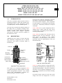
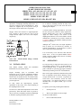
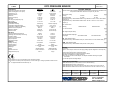
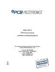
Model 113B24 ICP® Pressure Sensor Installation and Operating Manual For assistance with the operation of this product, contact PCB Piezotronics, Inc. Toll-free: 800-828-8840 24-hour SensorLine: 716-684-0001 Fax: 716-684-0987 E-mail: [email protected] Web: www.pcb.com Warranty, Service, Repair, and Return Policies and Instructions The information contained in this document supersedes all similar information that may be found elsewhere in this manual. Total Customer Satisfaction – PCB Piezotronics guarantees Total Customer Satisfaction. If, at any time, for any reason, you are not completely satisfied with any PCB product, PCB will repair, replace, or exchange it at no charge. You may also choose to have your purchase price refunded in lieu of the repair, replacement, or exchange of the product. Service – Due to the sophisticated nature of the sensors and associated instrumentation provided by PCB Piezotronics, user servicing or repair is not recommended and, if attempted, may void the factory warranty. Routine maintenance, such as the cleaning of electrical connectors, housings, and mounting surfaces with solutions and techniques that will not harm the physical material of construction, is acceptable. Caution should be observed to insure that liquids are not permitted to migrate into devices that are not hermetically sealed. Such devices should only be wiped with a dampened cloth and never submerged or have liquids poured upon them. Repair – In the event that equipment becomes damaged or ceases to operate, arrangements should be made to return the equipment to PCB Piezotronics for repair. User servicing or repair is not recommended and, if attempted, may void the factory warranty. Calibration – Routine calibration of sensors and associated instrumentation is recommended as this helps build confidence in measurement accuracy and acquired data. Equipment calibration cycles are typically established by the users own quality regimen. When in doubt about a calibration cycle, a good “rule of thumb” is to recalibrate on an annual basis. It is also good practice to recalibrate after exposure to any severe temperature extreme, shock, load, or other environmental influence, or prior to any critical test. PCB Piezotronics maintains an ISO9001 certified metrology laboratory and offers calibration services, which are accredited by A2LA to ISO/IEC 17025, with full traceablility to N.I.S.T. In addition to the normally supplied calibration, special testing is also available, such as: sensitivity at elevated or cryogenic temperatures, phase response, extended high or low frequency response, extended range, leak testing, hydrostatic pressure testing, and others. For information on standard recalibration services or special testing, contact your local PCB Piezotronics distributor, sales representative, or factory customer service representative. Returning Equipment – Following these procedures will insure that your returned materials are handled in the most expedient manner. Before returning any equipment to PCB Piezotronics, contact your local distributor, sales representative, or factory customer service representative to obtain a Return Materials Authorization (RMA) Number. This RMA number should be clearly marked on the outside of all package(s) and on the packing list(s) accompanying the shipment. A detailed account of the nature of the problem(s) being experienced with the equipment should also be included inside the package(s) containing any returned materials. PCB for a complete statement of our warranty. Expendable items, such as batteries and mounting hardware, are not covered by warranty. Mechanical damage to equipment due to improper use is not covered by warranty. Electronic circuitry failure caused by the introduction of unregulated or improper excitation power or electrostatic discharge is not covered by warranty. A Purchase Order, included with the returned materials, will expedite the turn-around of serviced equipment. It is recommended to include authorization on the Purchase Order for PCB to proceed with any repairs, as long as they do not exceed 50% of the replacement cost of the returned item(s). PCB will provide a price quotation or replacement recommendation for any item whose repair costs would exceed 50% of replacement cost, or any item that is not economically feasible to repair. For routine calibration services, the Purchase Order should include authorization to proceed and return at current pricing, which can be obtained from a factory customer service representative. Contact Information – International customers should direct all inquiries to their local distributor or sales office. A complete list of distributors and offices can be found at www.pcb.com. Customers within the United States may contact their local sales representative or a factory customer service representative. A complete list of sales representatives can be found at www.pcb.com. Toll-free telephone numbers for a factory customer service representative, in the division responsible for this product, can be found on the title page at the front of this manual. Our ship to address and general contact numbers are: Warranty – All equipment and repair services provided by PCB Piezotronics, Inc. are covered by a limited warranty against defective material and workmanship for a period of one year from date of original purchase. Contact DOCUMENT NUMBER: 21354 DOCUMENT REVISION: B ECN: 17900 PCB Piezotronics, Inc. 3425 Walden Ave. Depew, NY 14043 USA Toll-free: (800) 828-8840 24-hour SensorLineSM: (716) 684-0001 Website: www.pcb.com E-mail: [email protected] OPERATION MANUAL FOR QUARTZ PRESSURE SENSORS SERIES 102A, A03, A04, A06, A12, A15, A21, A22 SERIES 113A21, A22, A23, A24, A26, A27, A28 SERIES 113A31, A32, A33, A34, A36, A37, A38 SERIES 113B51, B52, B53 SERIES 113B31, B32, B33, B34, B36, B37, B38 1.0 INTRODUCTION This series of miniature dynamic pressure sensors is specifically designed for shock tube and blast wave measurements and for other applications requiring very high frequency, near non-resonant response. The figure above shows the components of the basic ICP® probe, i.e. the piezoelectric element and the ICP® source follower amplifier. These components are joined together as an inseparable sealed assembly at the factory. Disassembly should not be attempted in the field. The term used to describe the transient response of this model series is “Frequency Tailoring” and it encompasses several mechanical and electrical design features coupled with stringent in-process fabrication/test procedures with heavy emphasis on the shock tube as a tool. Series 113B20 are in a probe configuration and are installed with a hollow clamp nut with 5/16-24 external threads. The housing of these models is at electrical ground potential. 2.0 DESCRIPTION Although this series consists of sensors with three basic mechanical configurations and six different sensitivities, each model is basically similar in internal design. Series 113B30 are similar to the B20 Series with an additional feature; all Invar construction. The all Invar sensors are designed to have minimal susceptibility to thermal transient events and are specifically suited for high-temperature shock and blast measurements. + _ Connector Intergrated Circuit Amplifier Potting Mounting Clamp Nut Acceleration Compensation Mass and Plate M Quartz Plates Seal Ring Preload Sleeve Electrodes Housing 0.218 Dia Diaphragm Typical ICP® Probe Style Sensor Each utilizes the acceleration-compensated Series 113 quartz piezoelectric element coupled to a source follower type miniature electronics. (See “General Guide to ICP® Instrumentation,” G-0001B, for a detailed description of the ICP® concept.) Series 113: Probe Style Sensor Series 102 consist of the basic 113A20 Series probe, as in the above mentioned series, mounted in a 3/8-24 threaded mounting adaptor. The probe is installed at the factory in an "off ground" configuration, i.e. the probe body is insulated from the external mounting adaptor body. The Model 102A12 utilizes the same inner probe design as the above two designs but in a 3/8-24 Drawing Number: 21075 Revision: B ECN Number: 41425 1 OPERATION MANUAL FOR QUARTZ PRESSURE SENSORS SERIES 102A, A03, A04, A06, A12, A15, A21, A22 SERIES 113A21, A22, A23, A24, A26, A27, A28 SERIES 113A31, A32, A33, A34, A36, A37, A38 SERIES 113B51, B52, B53 SERIES 113B31, B32, B33, B34, B36, B37, B38 threaded adaptor with floating clamp nut to allow adjustment of diaphragm mounting depth where it is necessary to adapt to various wall thicknesses. These models are supplied only as low-pressure (250 psi and 100 psi) sensors and are also "off ground". Models 102A21 and 102A22 are high-temperature ICP® versions to 400 °F (204 °C), with a 3/8-24 straight threads adaptor and 1/8-27 NPT adaptor, respectively. Common black vinyl electrical tape has been found to be an effective insulating material in many cases. One or more layers may be used across the end of diaphragm and adaptor. A silicone rubber coating approximately .010” thick has also been proven effective in many applications. General Electric RTV type 106 is recommended. Apply the rubber coating to the surface of the diaphragm and allow it to cure in accordance with the manufacturer’s instructions. (If you have ordered the CA option, ablative coated models, further protection will not be necessary.) Although ICP® sensors have low-output impedance and in general are not affected by moisture, in extreme environments it is good practice to protect cable connections with shrink tubing. It is not necessary to use low-noise cable with this sensor series. In fact, an optional Model 070B09 Solder Connector Adaptor allows the use of ordinary two-wire cable if desired. Series 102: Thread Mount Design, GroundIsolated Sensor 3.0 INSTALLATION This manual contains outline and information for your specific model. installation Prepare mounting ports in accordance with instructions given in specific installation drawings, paying particular attention to sealing surfaces. These surfaces must be smooth and free from chatter marks, nicks and other irregularities which could preclude a pressure tight seal. To fully realize the high-frequency response capabilities of this sensor series, flush mounting of the diaphragm must be used. In some cases, where flash temperatures such as those generated by blasts and shock fronts are present, it may be necessary to thermally insulate the diaphragm to minimize signals generated by these effects. 4.0 It is only necessary to supply the sensor with a 2 to 20 mA constant current at +20 to +30 VDC through a current-regulating diode or equivalent circuit. (See guide G-0001B for powering and signal utilization information pertaining to all ICP® instrumentation). Most of the signal conditioners manufactured by PCB have an adjustable current feature allowing a choice of input currents from 2 to 20 mA. In general, for lowest noise (best resolution), choose the lower current ranges. For driving long cables (to several thousand feet), use higher current, up to 20 mA maximum. To operate system using a PCB signal conditioner: 1. Switch power on. 2. Wait several minutes for the IC amplifier to turn on and stabilize. 3. Drawing Number: 21075 Revision: B ECN Number: 41425 OPERATION Proceed with measurements. 2 OPERATION MANUAL FOR QUARTZ PRESSURE SENSORS SERIES 102A, A03, A04, A06, A12, A15, A21, A22 SERIES 113A21, A22, A23, A24, A26, A27, A28 SERIES 113A31, A32, A33, A34, A36, A37, A38 SERIES 113B51, B52, B53 SERIES 113B31, B32, B33, B34, B36, B37, B38 5.0 POLARITY The sensors in this series produce a positive-going output voltage for increasing pressure input. 6.0 calibrator or dead weight tester and readout is by recorder or storage oscilloscope. PCB offers a complete calibration service. Consult factory for details. LOW-FREQUENCY RESPONSE The low-frequency response of an ICP® system is determined by: 1. The discharge T.C. of the sensor 2. If AC-coupled at power unit, the coupling time constant. Consult Section 7.0 in guide G-0001B detailed explanation of low-frequency characteristics of ICP® instruments. 7.0 HIGH-FREQUENCY RESPONSE Frequency tailoring and the very high-natural frequency of the sensor give an extremely wide usable frequency range (beyond 100 kHz). Exceptionally fast response time (1 µsec) and clean, virtually non-resonant response to rapid step functions are also features of these sensors. As mentioned previously, the diaphragm must be flushmounted to fully realize the high-frequency response capabilities of this series. 8.0 CALIBRATION Piezoelectric sensors are dynamic devices, but static calibration means can be employed if discharge time constants are sufficiently long. Generally, static methods are not employed below several hundred seconds time constant. To employ static means, direct couple the sensor to the DVM readout using a T-Connector from the sensor jack or use the Model 484B in the calibrate mode. Apply pressure with dead weight tester and take readings quickly. Release pressure after each calibration point. For the shorter time constant, rapid step functions of pressure are generated by a pneumatic pressure pulse Drawing Number: 21075 Revision: B ECN Number: 41425 ICP is a registered trademark of PCB Piezotronics 3 Model Number Revision: C ICP® PRESSURE SENSOR 113B24 ECN #: 40791 Performance ENGLISH SI OPTIONAL VERSIONS Measurement Range(for ±5V output) Useful Overrange(for ± 10V output) Sensitivity(± 10 %) Maximum Pressure Resolution Resonant Frequency Rise Time Low Frequency Response(-5 %) Non-Linearity 1 kpsi 2 kpsi 5.0 mV/psi 10 kpsi 5 mpsi ≥ 500 kHz ≤ 1.0 µ sec 0.005 Hz ≤ 1.0 % FS 6895 kPa 13,790 kPa 0.725 mV/kPa 68,950 kPa 0.035 kPa ≥ 500 kHz ≤ 1.0 µ sec 0.005 Hz ≤ 1.0 % FS Optional versions have identical specifications and accessories as listed for the standard model except where noted below. More than one option may be used. ≤ 0.002 psi/g -100 to +275 °F ≤ 0.03 %/°F 3000 °F 2000 g pk 20,000 g pk ≤ 0.0014 kPa/(m/s²) -73 to +135 °C ≤ 0.054 %/°C 1649 °C 19,614 m/s² pk 196,140 m/s² pk Positive ≥ 100 sec 20 to 30 VDC 2 to 20 mA <100 Ohm 8 to 14 VDC Positive ≥ 100 sec 20 to 30 VDC 2 to 20 mA <100 Ohm 8 to 14 VDC Compression Quartz 17-4 Stainless Steel Invar Welded Hermetic 10-32 Coaxial Jack 0.21 oz Compression Quartz 17-4 Stainless Steel Invar Welded Hermetic 10-32 Coaxial Jack 6.0 gm [2] [1] [3] Environmental Acceleration Sensitivity Temperature Range(Operating) Temperature Coefficient of Sensitivity Maximum Flash Temperature Maximum Vibration Maximum Shock Electrical Output Polarity(Positive Pressure) Discharge Time Constant(at room temp) Excitation Voltage Constant Current Excitation Output Impedance Output Bias Voltage Physical Sensing Geometry Sensing Element Housing Material Diaphragm Sealing Electrical Connector Weight(with clamp nut) [4] [1] E - Emralon coating [5][6] Coating Emralon Emralon Electrical Isolation 108 Ohm 108 Ohm Supplied Accessory : Model 065A08 Isolation ring 0.250"OD x 0.218" ID x 0.027" thk anodized aluminum (3) Supplied Accessory : Model 065A22 Isolation Seal, .250" OD x .218" ID x .015", Torlon or Vespel (3) H - Hermetic Seal Sealing [6] Welded Hermetic Welded Hermetic J - Ground Isolated [6][7] N - Negative Output Polarity [6] S - Stainless Steel Diaphragm Diaphragm 316L Stainless Steel [6] 316L Stainless Steel W - Water Resistant Cable [5][6] Supplied Accessory : Model 060A03 Clamp nut, 5/16-24-2A thd, 1/4" hex, stainless steel (1) WM - Water Resistant Cable [5][6] Supplied Accessory : Model 060A05 Clamp nut M7 x 0.75-6g thd (1) NOTES: [1] Typical. [2] For +10 volt output, minimum 24 VDC supply voltage required. Negative 10 volt output may be limited by output bias. [3] Zero-based, least-squares, straight line method. [4] See PCB Declaration of Conformance PS023 for details. [5] Clamp nut installed prior to cable attachment [6] For sensor mounted in thread adaptor, see adaptor installation drawing for supplied accessories. [7] Used with optional mounting adaptor. All specifications are at room temperature unless otherwise specified. In the interest of constant product improvement, we reserve the right to change specifications without notice. ICP® is a registered trademark of PCB Group, Inc. SUPPLIED ACCESSORIES: Model 060A03 Clamp nut, 5/16-24-2A thd, 1/4" hex, stainless steel (1) Model 060A05 Clamp nut M7 x 0.75-6g thd (1) Model 065A02 Seal ring, sensor flush mount, 0.248" OD x 0.219" ID x 0.015" thk, brass (3) Model 065A05 Seal sleeve sensor recess mount 0.248" OD x 0.221" ID x 0.240" thk 17-4 (1) Entered: AP Engineer: MJK Sales: KWW Approved: BAM Spec Number: Date: 3/19/2013 Date: 3/19/2013 Date: 3/19/2013 Date: 3/19/2013 40647 3425 Walden Avenue, Depew, NY 14043 Phone: 716-684-0001 Fax: 716-684-0987 E-Mail: [email protected]