1
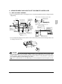
For CS-63DM1HPK
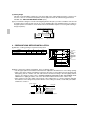
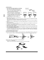
• Apply to the right side drain pan opening (3 locations) as shown in the figure.
Insert
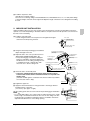
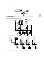
9-3 WIRING EXAMPLE
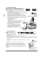
• Fit the power supply wiring of each unit with a switch and fuse as shown in the drawing.
COMPLETE SYSTEM EXAMPLE (3 systems)
Power supply
Power supply wiring
Outdoor unit
Main switch
Transmission wiring
Switch
Fuse
HR box
(Only for
Heat
recovery system)
Indoor unit
Remote controller
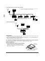
1. When using 1 remote controller for 1 indoor unit. (Normal operation)
Power supply
220-240V
Outdoor unit
Power supply
220-240V
Power supply
220-240V
Power supply
220-240V
Control box
50Hz
or L N
220V
IN/D OUT/D
F1 F2 F 1 F2
No. 1
System
60Hz
LN
P 1 P 2 F 1 F2 T1 T 2
Indoor unit A
50Hz
or
220V
L N
60Hz
LN
P 1 P 2 F 1 F2 T 1 T 2
Indoor unit B
P1 P2
English
L N
50Hz
or
220V
60Hz
LN
P 1 P 2 F1 F 2 T 1 T 2
Indoor unit C
P 1 P2
L N
50Hz
or
220V
60Hz
LN
P 1 P 2 F1 F 2 T 1 T 2
Most
downstream
indoor unit
P 1 P2
P1 P2
14