1
2
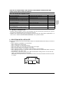
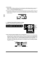
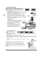
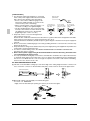
2. Nitrogen should be set to 0.02 Mpa (0.2 kg/cm ) with a pressure-reducing valve if brazing while inserting
nitrogen into the piping.
Pressure-reducing valve
Refrigerant piping
Part to be brazed
Taping
hands valve
Nitrogen
Nitrogen
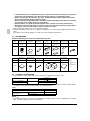
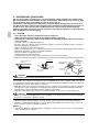
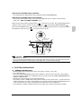
The flare nuts used must be those included with the main body.
• Refer to Table 2 for tightening torque.
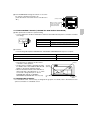
Table 2
φ 9.5
32.7 – 39.9N·m (333 – 407 kgf·cm)
12.6 – 13.0
φ 12.7
49.5 – 60.3N·m (504 – 616 kgf·cm)
15.8 – 16.2
φ 15.9
61.8 – 75.4N·m (630 – 770 kgf·cm)
19.0 – 19.4
φ 19.1
97.2 – 118.6N·m (990 – 1210 kgf·cm)
23.3 – 23.7
0
8.6 – 9.0
0
90 Ⳳ0.5
R0.4-0.8
A
14.2 – 17.2N·m (144 – 176 kgf·cm)
0
φ 6.4
Flare shape
0
Flare dimension
A (mm)
45 Ⳳ
2
Tightening torque
Pipe gauge
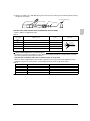
Not recommendable but in case of emergency
You must use a torque wrench but if you are obliged to install the unit without a torque wrench, you may
follow the installation method mentioned below.
After the work is finished, make sure to check that there is no gas leak.
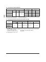
When you keep on tightening the flare nut with a spanner, there is a point where the tightening torque
suddenly increases. From that position, further tighten the flare nut the angle shown below:
Table 3
Pipe size
Further tightening angle
Recommended arm length of tool
φ 6.4 (1/4”)
60 to 90 degrees
Approx. 150mm
φ 9.5 (3/8”)
60 to 90 degrees
Approx. 200mm
φ 12.7 (1/2”)
30 to 60 degrees
Approx. 250mm
φ 15.9 (5/8”)
30 to 60 degrees
Approx. 300mm
φ 19.1 (3/4”)
20 to 35 degrees
Approx. 450mm
English
8