1
3VA10807-4C_Eng.fm Page 9 Friday, September 14, 2001 11:15 AM
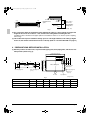
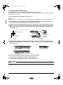
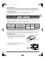
• When connecting the flare nut, coat the flare both inside and outside with ether oil or ester oil and initially
tighten by hand 3 or 4 turns before tightening firmly. (Refer to Fig. 17)
Torque wrench
Coated with ester oil or ether oil
Spanner
Piping union
Flare nut
Fig. 17
Fig. 16
CAUTION
Overtightening may damage the flare and cause leaks.
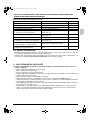
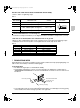
Use “ Tabel 2 ” as a reference if a torque wrench is not available. Once work is complete, make sure there is
no gas leaking. As the flare nut is tightened with the wrench, the torque will suddenly increase. From that position, tighten the nut to the angle shown on “ Tabel 2 ”.
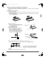
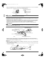
• Make absolutely sure to execute heat insulation works on the pipe-connecting section after checking gas
leakage by thoroughly studying the following figure and using the attached heat insulating materials for
fitting (6) and (7). (Fasten both ends with the clamps (4) (attached).) (Refer to Fig. 18)
• Wrap the sealing pad (9) (attached) only around the insulation for the joints on the gas piping side.
(Refer to Fig. 19)
CAUTION
Be sure to insulate any field piping all the way to the piping connection inside the unit. Any exposed piping
may cause condensation or burns if touched.
Small sealing pad (9) (attached)
Wrap from the bottom up
Insulation for gas pipe (6) (attached)
Insulation for local piping
(Part to be procured in the field)
(Up to the flare part)
Flare nut
Fig. 19
Flare nut
Gas piping
Insulation for field piping
(Part to be procured in the field)
Liquid piping
Insulation for liquid pipe (7) (attached)
Clamp (4) (attached) (× 4)
Attach to the bottom
(For both gas piping and liquid piping)
Fig. 18
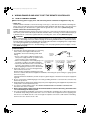
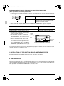
• When brazing the refrigerant piping, only begin brazing after having carried out nitrogen substitution
(NOTE 1) or while inserting nitrogen into the refrigerant piping (NOTE 2). Once this is done, connect the
indoor unit with a flared or a flanged connection.
NOTES
1. Refer to the “Manual for Multi Installation for Buildings” for directions on how to carry out nitrogen substitution. (Inquire with your dealer.)
2
2. Nitrogen should be set to 0.02 Mpa (0.2 kg/cm ) with a pressure-reducing valve if brazing while inserting
nitrogen into the piping.
Pressure-reducing valve
Refrigerant piping
Part to be brazed
Taping
hands valve
Nitrogen
Nitrogen
9
English