1
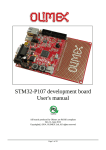
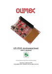
STM32-P107 development board
User's manual
All boards produced by Olimex are ROHS compliant
Rev. G, December 2013
Copyright(c) 2013, OLIMEX Ltd, All rights reserved
DISCLAIMER
© 2013 Olimex Ltd. Olimex®, logo and combinations thereof, are registered trademarks of Olimex Ltd. Other product
names may be trademarks of others and the rights belong to their respective owners.
The information in this document is provided in connection with Olimex products. No license, express or implied
or otherwise, to any intellectual property right is granted by this document or in connection with the sale of
Olimex products.
This hardware design of STM32-P107 is neither public not open-source. Any copying of the product would result in
copyright infringement.
The software is released under open source terms regarding the code written by Olimex. Every other else (libraries,
ready-to-use-files, etc) follow their owner's copyright.
It is possible that the pictures in this manual differ from the latest revision of the board.
The product described in this document is subject to continuous development and improvements. All particulars of the
product and its use contained in this document are given by OLIMEX in good faith. However all warranties implied or
expressed including but not limited to implied warranties of merchantability or fitness for purpose are excluded. This
document is intended only to assist the reader in the use of the product. OLIMEX Ltd. shall not be liable for any loss or
damage arising from the use of any information in this document or any error or omission in such information or any
incorrect use of the product.
This evaluation board/kit is intended for use for engineering development, demonstration, or evaluation purposes only
and is not considered by OLIMEX to be a finished end-product fit for general consumer use. Persons handling the
product must have electronics training and observe good engineering practice standards. As such, the goods being
provided are not intended to be complete in terms of required design-, marketing-, and/or manufacturing-related
protective considerations, including product safety and environmental measures typically found in end products that
incorporate such semiconductor components or circuit boards.
Olimex currently deals with a variety of customers for products, and therefore our arrangement with the user is not
exclusive. Olimex assumes no liability for applications assistance, customer product design, software performance, or
infringement of patents or services described herein.
THERE IS NO WARRANTY FOR THE DESIGN MATERIALS AND THE COMPONENTS
USED TO CREATE STM32-P107. THEY ARE CONSIDERED SUITABLE ONLY FOR
STM32-P107.
Page 2 of 19
INTRODUCTION
STM32-P107 prototype board provides easy way for developing and prototyping with the new
STM32F107VCT6 connectivity line microcontroller, produced by STMicroelectronics. STM32P107 has JTAG port for programming and debugging, USB_OTG, user button, two status LEDs,
and most of the GPIOs are on extension headers where you can connect your additional circuits.
BOARD FEATURES
- CPU: STM32F107VCT6 32 bit ARM-based microcontroller with 256 KB Flash, 64 KB RAM,
USB OTG, Ethernet, 10 timers, 2 CANs, 2 ADCs, 14 communication interfaces
- JTAG connector with ARM 2x10 pin layout for programming/debugging
- USB_OTG connector
- USB_HOST connector
- 100Mbit Ethernet
- RS232
- Mini SD/MMC card connector
- UEXT connector
- Power jack
- Two user buttons
- RESET button and circuit
- Two status LEDs
- Power-on LED
- 3V battery connector
- Extension port connectors for many of microcontrollers pins
- PCB: FR-4, 1.5 mm (0,062"), soldermask, silkscreen component print
- Dimensions: 132.08x96.52mm (5.2x3.8")
ELECTROSTATIC WARNING
The STM32-P107 board is shipped in protective anti-static packaging. The board must not be
subject to high electrostatic potentials. General practice for working with static sensitive devices
should be applied when working with this board.
Page 3 of 19
BOARD USE REQUIREMENTS
Cables: The cable you will need depends on the programmer/debugger you use. If you use ARMJTAG, you will need LPT cable, if you use ARM-USB-OCD, ARM-USB-OCD-H, ARM-USBTINY, or ARM-USB-TINY-H you will need 1.8 meter USB A-B cable, for ARM-USB-OCD and
ARM-USB-OCD-H you will need RS232 cable, too.
Hardware: Programmer/Debugger – one of the Olimex ARM Programmers: ARM-JTAG, ARMJTAG-EW, ARM-USB-OCD, ARM-USB-OCD-H, ARM-USB-OCD-TINY, ARM-USB-OCD-H.
Note that Olimex OpenOCD debuggers lack SWD interface by default. There is the adapter ARMJTAG-SWD that adds SWD to any of the programmers/debuggers mentioned above.
Additionally you can use our ARM-JTAG-COOCOX debugger which has both JTAG and SWD
interfaces and works with CooCox IDE natively and with IAR EW and Keil uVision via pluggins.
Software: ARM C compiler
PROCESSOR FEATURES
STM32-P107 board uses the ARM-based 32-bit microcontroller STM32F107VCT6 with the
following features:
– Core: ARM 32-bit Cortex™-M3 CPU
– 72 MHz maximum frequency, 1.25 DMIPS/MHz (Dhrystone 2.1) performance at 0 wait
state memory access
– Single-cycle multiplication and hardware division
– Memories
– 256 Kbytes of Flash memory
– 64 Kbytes of SRAM
– Clock, reset and supply management
– 2.0 to 3.6 V application supply and I/Os
– POR, PDR, and programmable voltage detector (PVD)
– 25 MHz crystal oscillator
– Internal 8 MHz factory-trimmed RC
– Internal 40 kHz RC with calibration
– 32 kHz oscillator for RTC with calibration
– Low power
– Sleep, Stop and Standby modes
– VBAT supply for RTC and backup registers
– 2 × 12-bit, 1 µs A/D converters (16 channels)
– Conversion range: 0 to 3.6 V
– Sample and hold capability
– Temperature sensor
– up to 2 MSps in interleaved mode
– 2 × 12-bit D/A converters
– DMA: 12-channel DMA controller
– Supported peripherals: timers, ADCs, DAC, I2Ss, SPIs, I2Cs and USARTs
Page 4 of 19
– Debug mode
– Serial wire debug (SWD) & JTAG interfaces
– Cortex-M3 Embedded Trace Macrocell™
– 80 fast I/O ports
– 80 I/Os, all mappable on 16 external interrupt vectors and almost all 5 V-tolerant
– 10 timers
– four 16-bit timers, each with up to 4 IC/OC/PWM or pulse counter and quadrature
(incremental) encoder input
– 1 × 16-bit motor control PWM timer with dead-time generation and emergency stop
– 2 × watchdog timers (Independent and Window)
– SysTick timer: a 24-bit downcounter
– 2 × 16-bit basic timers to drive the DAC
– 14 communication interfaces
– 2 × I2C interfaces (SMBus/PMBus)
– 5 USARTs (ISO 7816 interface, LIN, IrDA capability, modem control)
– 3 SPIs (18 Mbit/s), 2 with a multiplexed I2S interface that offers audio class accuracy via
advanced PLL schemes
– 2 × CAN interfaces (2.0B Active) with 512 bytes of dedicated SRAM
– USB 2.0 full-speed device/host/OTG controller with on-chip PHY that supports
HNP/SRP/ID with 1.25 Kbytes of dedicated SRAM
– 10/100 Ethernet MAC with dedicated DMA and SRAM (4 Kbytes): IEEE1588 hardware
support, MII/RMII available on all packages
– CRC calculation unit, 96-bit unique ID
Page 5 of 19
BLOCK DIAGRAM
Page 6 of 19
MEMORY MAP
Page 7 of 19
SCHEMATIC
STM32-P107, board revision C
OLIMEX LTD, PLOVDIV, BULGARIA 2013
USB CIRCUIT
H
O
H
O
H
USB_HOST
2
100nF
C8
10uF/6.3V
C7
100nF
C5
100nF
C4
4.7uF/6.3V
C3
2
100nF
C1
O
1
C9
10uF/6.3V
C10
100nF
C11
C13
C12
C14
100nF
C17
NA
USB_OTG
100nF
NA(47pF)
NA(47pF)
C15
C16
2.2uF/6.3V
100nF
D1
3V_BAT
WF2S
BAT54C
1
3
2
1
0
SD/MMC
JTAG
HN1x3
2
1
B0_0/B0_1
C18
27pF
C19
27pF
C2022uF/6.3V
C21
10pF
C23
10pF
C2222uF/6.3V
Ethernet
22uF/6.3V
C26
22uF/6.3V
C25
22uF/6.3V
C29
100nF
C28
100nF
C27
C30
C31
2.2uF/6.3V
100nF
C24
100nF
BUTTONS
C32
100nF
D2
1N4148
RS232
C33
C5510uF/6.3V
C35
100nF
C34
100nF
C36
100nF
C37
100nF
100nF
CD1
4
VDD
E/D
2
UEXT
3
100nF
HN1x2(Open)
1
C38
BOOT0_E
1
D3
2
C39
100nF
1N4148
VSS
OUT
NA(6NC2-50MHz)
POWER SUPPLY CIRCUIT
3.3V
3.3VA
2
+5V
3.3V_E
STATUS LEDS
1
CLOSE
RESET CIRCUIT
3.3VA_E
2.2uF/6.3V
C41
22uF/6.3V
C51
22uF/6.3V
C50
22uF/6.3V
C48
100nF
C47
22uF/6.3V
C46
22uF/6.3V
C49
NA(10uF/6.3V)
C52
22uF/6.3V
C45
C43
100nF
NA(10uF/6.3V)
C40
470uF/16VDC
100nF
C44
1
CLOSE
6VAC
(6.5-9)VDC
1
0
2
3
1
2
D4
+
3.3VA_MCU_E
CLOSE
100nF
C2
CLOSE
100nF
C6
1
https://www.olimex.com
3.3V_MCU_E
B1_0/B1_1
HN1x3
C42
100nF
STM32-P107, board revision C
C53
AGND
C54
OLIMEX LTD, PLOVDIV, BULGARIA 2013
100nF
https://www.olimex.com
BOARD LAYOUT
POWER SUPPLY CIRCUIT
STM32-P107 can take power from three sources:
– PWR connector where (6.5-9)V DC or 6V AC is applied by external power source.
– +5V_ OTG-PWR from USB OTG
– +5V_JTAG from JTAG
The programmed board power consumption is about 70 mA.
RESET CIRCUIT
STM32-P107 reset circuit includes JTAG connector pin 15, U2 (STE101P) pin 28 (RESET), R73(10k),
R74(330Ohm), R75(100Ohm/1%), C55(100nF), STM32F107 pin 14 (NRST) and RESET button.
CLOCK CIRCUIT
Quartz crystal 25 MHz is connected to STM32F107 pin 12 (OSC_IN) and pin 13 (OSC_OUT).
Quartz crystal 32.768kHz is connected to STM32F107 pin 8 (PC14/OSC32_IN) and pin 9
(PC15/OSC32_OUT).
JUMPER DESCRIPTION
PWR_SEL
When position 1-2 is shorted – the board is power supplied from JTAG.
When position 3-4 is shorted – the board is power supplied from USB_OTG.
When position 5-6 is shorted – the board is power supplied from External
source.
Default state is – position 5-6 – shorted.
B0_0/B0_1
When this jumper is in position B0_1 – BOOT0 is connected to 3.3V, and
jumper is in position B0_0 – BOOT0 is connected to GND.
Default state is B0_0.
B1_0/B1_1
When this jumper is in position B1_1 – BOOT1 is connected to 3.3V, and
jumper is in position B1_0 – BOOT1 is connected to GND.
Default state is B1_0.
power
when the
when the
VBUS
When is in position “H” - connects +5V_HOST_PWR to OTG_VBUS.
When is in position “O” - connects +5V_OTG_PWR to OTG_VBUS.
Default state is “O”.
USB_D+
When is in position “H” - connects USB_HOST_D+ to OTG_DP.
When is in position “O” - connects USB_OTG_D+ to OTG_DP.
Default state is “O”.
USB_DWhen is in position “H” - connects USD_HOST_D- to OTG_DM.
When is in position “O” - connects USB_OTG_D- to OTG_DM.
Default state is “O”.
PWDW_D
When is closed – disables Ethernet transceiver (STE101P) Power Down Mode. STE101P
is active.
Default state is closed.
3.3V_MCU_E
Enable microcontroller 3.3V power supply
Default state is closed.
3.3V_E
Enable regulator VR2 (3.3V) - LM1117
Default state is closed.
3.3VA_E
Enables board 3.3V analog power supply.
Default state is closed.
3.3VA_MCU_E
Enables microcontroller 3.3V analog power supply.
Default state is closed.
GNDA_E
Enables board analog GND.
Default state is closed.
R-T
Connects RST to TRST
Default state is open.
RST_E, BOOT_E jumpers
Note that it is recommended to move those jumpers together – either both
open or both should be closed.
When both are closed RS232 boot is enabled.
Default states are RST_E – open; BOOT_E – open.
INPUT/OUTPUT
Status LED1 (green) with name STAT1 connected to STM32F107 pin 63
(PC6/I2S2_MCK/TIM3_CH1).
Status LED2 (yellow) with name STAT2 connected to STM32F107 pin 64
(PC7/I2S3_MCK/TIM3_CH2).
Power-on LED (red) with name PWR – this led shows that +3.3V is applied to the board.
User button with name WKUP connected to STM32F107 pin 23 (PA0/WKUP).
User button with name TAMPER connected to STM32F107 pin 7 (PC13/TAMPER-RTC).
Reset button with name RESET connected to STM32F107 pin 14 (NRST).
should be
CONNECTOR DESCRIPTIONS
JTAG
The JTAG connector allows the software debugger to talk via a JTAG (Joint Test Action Group) port
directly to the core. Instructions may be inserted and executed by the core thus allowing STM32F107
memory to be programmed with code and executed step by step by the host software.
For more details please refer to IEEE Standard 1149.1 - 1990 Standard Test Access Port and Boundary
Scan Architecture and STM32F107 datasheets and users manual.
Pin #
Signal name
Pin #
Signal name
1
3.3V
2
3.3V
3
TRST
4
GND
5
TDI
6
GND
7
TMS
8
GND
9
TCK
10
GND
11
PULL-DOWN
12
GND
13
TDO
14
GND
15
RST
16
GND
17
PULL-DOWN
18
GND
19
+5V_JTAG
20
GND
PWR_JACK
Pin #
Signal name
1
Power input
2
GND
USB_HOST
Pin #
Signal name
1
+5V_HOST_PWR
2
USB_HOST_D-
3
USB_HOST_D+
4
GND
USB_OTG
Pin #
Signal name
1
+5V_OTG_PWR
2
USB_OTG_D-
3
USB_OTG_D+
4
OTG_ID
5
GND
3V_BAT
Pin #
Signal name
1
VBAT
2
GND
RS232
The RS232 port can be used for communication when in bootloader mode. To enter bootloader mode you
need to close RST_E and BOOT0_E jumpers. Note that the default position of those jumpers is closed,
e.g. bootloader mode disabled.
Pin #
Signal name
1
NC
2
T1OUT
3
R1IN
4
NC
5
GND
6
NC
7
CTS
8
RTS
9
NC
UEXT
Pin #
Signal name
1
3.3V
2
GND
3
USART2_TX
4
USART2_RX
5
I2C1_SCL
6
I2C1_SDA
7
SPI3_MISO
8
SPI3_MOSI
9
SPI3_SCK
10
CS_UEXT
LAN
Pin #
Signal name chip side
Pin #
Signal name chip side
1
TX+
5
Not connected (NC)
2
TX-
6
VDD
3
VDD
7
RX+
4
Not connected (NC)
8
RX-
LED
Color
Usage
Right
Green
Link status
Left
Yellow
Activity status
SD/MMC
Pin #
Signal name
1
2
3
4
5
6
7
8
9
10
11
12
MCIDAT2
CS_MMC
SPI3_MOSI
3.3V
SPI3_SCK
GND
SPI3_MISO
MCIDAT1
Not connected
Not connected
Not connected
Not connected
MECHANICAL DIMENSIONS
All measures are in mils.
AVAILABLE DEMO SOFTWARE
All demo examples are available at the board's web-page
(https://www.olimex.com/Products/ARM/ST/STM32-P107/) and wiki article
(https://www.olimex.com/wiki/STM32-P107). Make sure that the demo you download is compatible with
the board revision you have! The board revision is printed on STM32-P107 itself.
REVISION AND ORDERING INFORMATION
STM32-P107 – fully assembled and tested
You can purchase directly from our online shop or from any of our distributors. Note that usually it is
faster and cheaper to purchase Olimex products from our distributors. List of confirmed Olimex LTD
distributors and resellers: https://www.olimex.com/Distributors.
Please visit https://www.olimex.com/ for more info.
Manual revision history:
REV. I
REV. A
REV. B
REV. C
REV. D
REV. E
REV. F
REV.G
- created December 2009
- edited by TU December 2010
- demo software added and mechanical dimensions detaile
- rev. A schematic and added more programmers in BOARD USE
REQUIREMENTS.
- edited June 2011 – changed schematic
- changed schematics to rev. B, added board revision history
- added BOOT0_E, RST_E description, changed dimensions, updated
revision B pictures, updated disclaimer
- updated the information to fit board revision C, updated schematics,
improved document layout, added product support information, updated
links
Board revision history:
rev. A
========
1. ST2052BD is exchanged with LM3526-L.
2. SD/MMC signals are changed as follows:
SPI1_MOSI ->
SPI3_MOSI
SPI1_SCK
->
SPI3_SCK
SPI1_MISO ->
SPI3_MISO
and SPI1_NSS renamed to CS_MMC
3. Changed the polarity to + of C36
rev. B
========
1. All element libraries are now updated
2. Ethernet PHY is changed from STE101P to MICREL's one - KS8721BLMM
3. All 10uF/6.3V/TANT are changed to 0805 and a lot of element names are changed.
4. PWR_SEL jumpers are replaced by diodes.
5. USART3 is connected to UEXT while USART2 is connected to RS232 and bootloader functionality is
enabled! Two additional jumpers are added!!!
6. Added UEXT_PWR_E jumper!
7. A lot jumpers are added into jumpers description table
rev. C
========
1. L2 is now placed further from USB_HOST connector to avoid contact
2. Ethernet PHY Micrel KS8721 is changed to LAN8710A-EZC in RMII
3. Changed C18 from 100n to 4.7uF/6.3V according to the datasheet. C18 is now renamed C3.
4. STAT1, STAT2 and PWR_LED were changed to 0603 and its resistors to 2.2k.
5. SD/MMC capacitor was replaced by 2x22uF/6.3V capacitors.
6. LM3526 was exchanged with MIC2026-1YM and connection between pin 1 and pin4 was swapped
because the default EN level is opposite.
7. All tantalum capacitors are changed to ceramic.
8. Optimizations in the values of few other elements as well.
9. R28(0R) was changed to 10k, C55=10uF/6.3V was added and RST connection was removed from the
PHY!
WARRANTY AND SUPPORT
For product support, hardware information and error reports mail to: [email protected]. All document
or hardware feedback is welcome. Note that we are primarily a hardware company and our software
support is limited. Please consider reading the paragraph below about the warranty of Olimex products.
All goods are checked before they are sent out. In the unlikely event that goods are faulty, they
must be returned, to OLIMEX at the address listed on your order invoice.
OLIMEX will not accept goods that have clearly been used more than the amount needed to evaluate
their functionality.
If the goods are found to be in working condition, and the lack of functionality is a result of lack
of knowledge on the customers part, no refund will be made, but the goods will be returned to the
user at their expense.
All returns must be authorized by an RMA Number. Email [email protected] for authorization number
before shipping back any merchandise. Please include your name, phone number and order number in your
email request.
Returns for any unaffected development board, programmer, tools, and cables permitted within 7 days
from the date of receipt of merchandise. After such time, all sales are considered final.
Returns of incorrect ordered items are allowed subject to a 10% restocking fee. What is unaffected?
If you hooked it to power, you affected it. To be clear, this includes items that have been soldered
to, or have had their firmware changed. Because of the nature of the products we deal with
(prototyping electronic tools) we cannot allow returns of items that have been programmed, powered
up, or otherwise changed post shipment from our warehouse.
All returned merchandise must be in its original mint and clean condition. Returns on damaged,
scratched, programmed, burnt, or otherwise 'played with' merchandise will not be accepted.
All returns must include all the factory accessories which come with the item. This includes any InCircuit-Serial-Programming cables, anti-static packing, boxes, etc.
With your return, enclose your PO#. Also include a brief letter of explanation of why the merchandise
is
being
returned
and
state
your
request
for
either
a
refund
or
an
exchange.
Include
the
authorization number on this letter, and on the outside of the shipping box.
Please note: It is your responsibility to ensure that returned goods reach us. Please use a reliable
form of shipping. If we do not receive your package we will not be held liable.
Shipping and handling charges are not refundable. We are not responsible for any shipping charges of
merchandise being returned to us or returning working items to you.
The full text might be found at https://www.olimex.com/wiki/GTC#Warranty for future reference.