1
Document Details
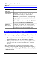
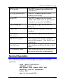
To Change the values on the right, double-click on the field,
and change the “Default Value” in the dialog box. Fields will
be updated on printing.
Client Details
Firm Name
Generic Name
IP Sharing Device
one_port (no Dial-in function)
SP860A/B
File Details
File: D:\IPS\Neutral\SP860A/B.doc
File size
800,256
Number of Pages
83
Date Printed
February 23, 1999
SP860A/B
IP Sharing Device
User’s Guide
P/N: 9560650101
FCC Statement:
This device complies with Part 15 of the FCC Rules. Operation
is subject to the following two conditions:
(1) This device may not cause harmful interference.
(2) This device must accept any interference received,
including interference that may cause undesired operation.
CE Marking Warning
This is a Class A product. In a domestic environment this
product may cause radio interference in which case the user
may be required to take adequate measures.
Copyright 1998. All Rights Reserved.
Document Version: 1.0
All trademarks and trade names are the properties of their
respective owners.
TABLE OF CONTENTS
CHAPTER 1 INTRODUCTION ...........................................1
IP Sharing Device Features ............................................2
Package Contents ............................................................5
Description - SP860A/B ..................................................6
LED Status Table ............................................................7
DIP Switches Table .......................................................10
CHAPTER 2 INSTALLATION...........................................13
Requirements.................................................................13
Procedure.......................................................................13
CHAPTER 3 CONFIGURATION ......................................15
IP Sharing Device Configuration.................................15
Configuration Program ................................................16
CHAPTER 4 INTERNET ACCESS....................................20
Overview ........................................................................20
Port Configuration ........................................................22
PC Configuration ..........................................................26
DHCP Server Configuration ........................................28
Router Configuration....................................................29
Operation - Internet Access..........................................29
Accessing AOL ..............................................................29
CHAPTER 5 ADVANCED PORT SETTINGS .................31
Overview ........................................................................31
Advanced Port Screen...................................................32
Port Settings...................................................................33
Modem/ISDN Settings...................................................33
Script File.......................................................................34
CompuServe Script .......................................................36
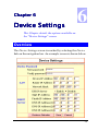
CHAPTER 6 DEVICE SETTINGS.....................................39
Overview ........................................................................39
Device Password ............................................................41
LAN Settings..................................................................41
i
DHCP Server................................................................. 43
CHAPTER 7 ACCESS CONTROL.................................... 46
Overview........................................................................ 46
Access Control Screen .................................................. 46
Workstation Data ......................................................... 49
CHAPTER 8 DIAL-IN ACCESS ........................................ 67
Overview........................................................................ 67
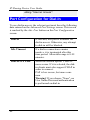
Port Configuration for Dial-In .................................... 68
User Configuration for Dial-in .................................... 69
Remote User Configuration ......................................... 72
CHAPTER 9 E-MAIL.......................................................... 74
Overview........................................................................ 74
Account Information .................................................... 75
User Information .......................................................... 76
DNS Address ................................................................. 78
E-Mail Program Configuration ................................... 79
Sharing E-Mail Example.............................................. 80
Management of Shared E-Mail ................................... 82
CHAPTER 10 ROUTING.................................................... 84
Overview........................................................................ 84
IP Sharing Device Configuration ................................ 84
Router Configuration ................................................... 86
Routing Example .......................................................... 88
CHAPTER 11 STATUS & MONITORING....................... 90
Overview........................................................................ 90
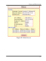
Status Screen ................................................................. 90
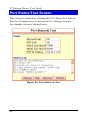
Port Status/Test Screen ................................................ 94
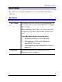
APPENDIX A TROUBLESHOOTING............................ 100
Overview...................................................................... 100
Problems ...................................................................... 100
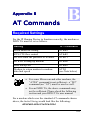
APPENDIX B AT COMMANDS ...................................... 105
Required Settings........................................................ 105
Finding the current Initial String.............................. 106
AT Commands ............................................................ 108
ii
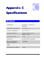
APPENDIX C SPECIFICATIONS ...................................113
SP860A/B ...........................................................................
iii
1
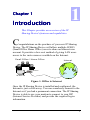
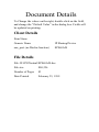
This Chapter provides an overview of the IP
Sharing Device's features and capabilities.
C
ongratulations on the purchase of your new IP Sharing
Device. The IP Sharing Device will allow multiple SOHO
(Small Office Home Office) users to share an Internet user
account. It provides a low-cost method of giving LAN users
access to the vast resources available on the Internet.
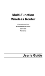
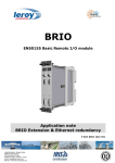
S m all O ffice / H om e O ffic e
Internet
M o de m
W ide L ink
Figure 1: Office to Internet
Once the IP Sharing Device is installed and configured, the
Internet is just a click away. You can seamlessly connect to the
Internet as if you had a permanent connection. The IP Sharing
Device is able to use your modem to connect to your ISP
(Internet Service Provider) and provide the required log-in
information.
1
IP Sharing Device User Guide
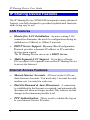
IP Sharing Device Features
The IP Sharing Device SP860A/B incorporates many advanced
features, carefully designed to provided sophisticated functions
while being easy to use.
LAN Features
•
Hassle-free LAN Installation. An auto-sensing LAN
connection eliminates the need for configuration during installation in a 10Base2 or 10BaseT network.
•
DHCP Server Support. Dynamic Host Configuration
Protocol provides a dynamic IP address to PCs and other
devices upon request.
The IP Sharing Device can act as a DHCP Server.
•
Multi Segment LAN Support. If you have a Router,
PCs on other LAN segments can use the IP Sharing Device
to access the Internet.
Internet Access Features
•
Shared Internet Accounts. All users on the LAN can
share Internet Accounts. You need only 1 account for each
modem, not 1 account for each user.
•
Dial-On-Demand & Auto-Disconnect. A connection
is established to the Internet as required, and automatically
disconnected when no longer needed. This reduces on-line
charges to the minimum possible level.
•
PPP Authentication. This is used to validate the log-on
to your Internet Service Provider.
2
Introduction
•
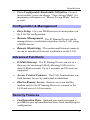
User-Configurable Bandwidth Utilization. On multiport models, users can choose “Time Saving Mode” for
maximum performance or “Money Saving Mode” for lower costs.
Configuration & Management
•
Easy Setup. Use your WEB browser from anywhere on
the LAN for configuration.
•
Remote Management. The IP Sharing Device can be
managed from a workstation anywhere on the LAN, using
a WEB browser.
•
Remote Monitoring. The modem and Internet connection can be monitored from any workstation on the LAN.
Advanced Functions
•
E-Mail Gateway. The IP Sharing Device can act as a
Gateway for incoming E-Mail, allowing LAN users to
share E-Mail accounts. Up to 4 accounts and 50 users are
supported.
•
Access Control Features. The LAN Administrator can
limit Internet Access by individual workstations.
•
Dial-in Remote Access. Remote users can dial the
modem and use the IP Sharing Device to connect to the
LAN and access LAN resources.
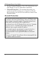
Security Features
•
Configuration Data. Optional password protection is
provided to prevent unauthorized users from modifying the
configuration.
3
IP Sharing Device User Guide
•
Access Control Features. The LAN Administrator can
limit Internet Access by individual workstations.
•
Firewall Protection. All incoming data packets are
monitored and all incoming server requests are filtered,
thus protecting your network from malicious attacks from
external sources.
)LUHZDOO#3URWHFWLRQ
The firewall protection provided by the IP Sharing Device is
an intrinsic side effect of IP sharing. All users on the LAN
share a single external IP address. From the external viewpoint, there is no network, only a single device.
For internal users, the IP Sharing Device acts as a “transparent proxy server”, translating the multiple internal IP
addresses into a single external IP address.
For external requests, any attempt to connect to local resources are blocked. The IP Sharing Device will not
“reverse translate” from a global IP address to a local IP
address.
This type of “natural” firewall provides an impregnable barrier against malicious attacks.
4
Introduction
Package Contents
The following items should be included:
•
The IP Sharing Device Unit
•
Power Adapter
•
This User’s Manual
If any of the above items are damaged or missing, please
contact your dealer as soon as possible.
5
IP Sharing Device User Guide
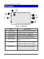
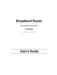
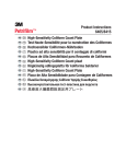
SP860A/B
Figure 2: SP860A/B
Item
6
Description
1
Power port
Insert the power adapter plug here.
2
10BaseT port
Connect 10BaseT cabling here.
3
10Base2 port
Connect 10Base2 cabling here.
4
Serial Port
Connect the modem to this port.
5
DIP switches
Refer to the following Dip Switches
Table.
6
Error LED
Indicates an error, but will normally
light up during power On. See the
LED Status Table for more details.
7
Link LED
This LED should be ON during
normal operation. See the following
LED Status Table for more details.
Introduction
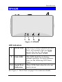
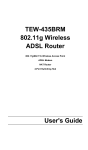
SP862B
Figure 3: SP862B
LED Indicators
1
Error LED
This LED is used to indicate an error,
but it will normally light up during
power On. See the following LED
Status Table for more details.
2
Link LED
This LED should be on during
normal operation. For more information, see the following LED Status
Table .
3, 4
Serial Port
Indicators
These LEDs flash when the relevant
port is in use.
See Figure 5: Back Panel on page 9 for connector details.
7
IP Sharing Device User Guide
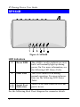
SP864B
Figure 4: SP864B
LED Indicators
1
Error LED
This LED is used to indicate an error,
but it will normally light up during
power On. For more information, see
the following LED Status Table.
2
Link LED
This LED should be on during
normal operation. For more information, see the following LED Status
Table.
3, 4
5, 6
Serial Port
Indicators
These LEDs flash when the relevant
port is in use.
See the following Back Panel diagram for connector details.
8
Introduction
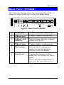
Back Panel (SP864B )
The following diagram shows the back panel of the. The is
identical except for having 2 serial ports rather than 4.
Figure 5: Back Panel (SP864B)
1
Power port
Connect the power adapter here.
2
10Base2 port
Connect 10Base2 cabling here.
3
10BaseT LED
indicator.
This will light when the 10BaseT
connector is in use.
4
10BaseT port
Connect 10BaseT cabling here.
5
DIP switches
Set Normal or Configuration
mode. See the following Dip
Switches Table for details.
6
Serial Ports
Connect the modems to these
ports. The has 2 ports; the has 4
ports.
Port 1, used for configuration, is
closest to the side of the device.
9
IP Sharing Device User Guide
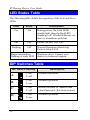
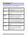
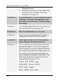
LED Status Table
The following table details the operation of the Link and Error
LEDs.
Link
Error
Description
On
On
During power On, both LEDs
should light, then the Red LED
should go off. If both LEDs stay on,
there is a hardware problem.
On
Off
Power On Self Test OK.
Flashing
Off
Normal Operation (Receiving
Packets from LAN).
Rapid intermittent
flashing of each LED
Hardware error. Contact your
dealer for technical support.
DIP Switches Table
DIP Switch Setting
Description
A
1=off
2=off
Normal Operation.
B
1=off
2=on
Normal Operation.
C
1=on
2=off
Restore Default IP Address and
clear Password. (See next section)
D
1=on
2=on
Normal Operation.
10
Introduction
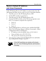
Restore Default IP Address
and Clear Password
If the IP Sharing Device's IP Address or password is lost, the
following procedure can be used to recover from this situation.
1. Turn the power to the IP Sharing Device OFF.
2. Set the DIP switches to position C.
3. Turn the power to the IP Sharing Device ON.
4. Operate the DIP switches in the following sequence (you
have 15 seconds to complete the sequence):
5.
6.
•
Set to A
•
Set to C
• Set to A
The IP Sharing Device will now reset, and the Red LED
flash. The following changes will have been made. (Other
configuration data is unchanged.)
•
IP Address set to its default value of 192.168.0.1
•
Network Mask set to 255.255.255.0
• The password cleared (no password).
You can now connect to the IP Sharing Device and make
any configuration changes required.
If the DIP switches are simply left at position "C", the IP Sharing Device will function
normally.
11
IP Sharing Device User Guide
This page was deliberately left blank
12
2
This Chapter explains how to install the IP
Sharing Device in your LAN.
Requirements
•
Ethernet Network employing 10BaseT or 10Base2 cable
and the TCP/IP protocol.
•
External modem or ISDN TA (Terminal Adapter).
•
Internet Access account with a local ISP (Internet Service
Provider).
Procedure
1. Choose an Installation Site
Select a place on the network to install the IP Sharing Device.
Remember that you need a phone jack and power outlets near
your chosen location.
2. Connect Network Cable
The IP Sharing Device supports two types of network cables:
•
Thin Ethernet (10Base2, BNC connector)
•
Twisted Pair Ethernet (10BaseT, RJ-45 connector).
13
IP Sharing Device User Guide
During power up, the unit automatically detects the type of
network cable and adjusts to that environment. Simply connect
the cable to the IP Sharing Device in the normal manner.
Do not connect both types of cable or
change the network cable while the IP
Sharing Device is powered On.
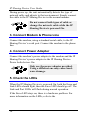
3. Connect Modem & Phone Line
Connect the modem, using a standard serial cable, to the IP
Sharing Device’s serial port. Connect the modem to the phone
line.
4. Connect Power Adapter
Connect the modem’s power adapter to the modem and the IP
Sharing Device’s power adapter to the IP Sharing Device.
Power both devices On.
Only use the power adapter provided.
Using a different one may cause hardware damage.
5. Check the LEDs
When the IP Sharing Device is powered On, both the Error and
Link LEDs should light, then the Error LED should go off. The
Link and Port LEDs will flash during normal operation.
If the Error LED stays on, there is a hardware problem. For
more information on the LEDs, refer to the
14
3
This Chapter contains an overview of the
configuration process.
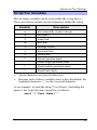
IP Sharing Device Configuration
The required configuration depends on which features and
functions of the IP Sharing Device you wish to use. Use the
table below to locate detailed instructions for the required
functions.
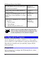
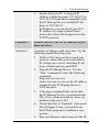
To Do this
Refer to
Provide Internet Access to all LAN
users
Chapter 4:
Internet Access
Configure for:
Chapter 5:
Advanced Port
Settings
•
A non-standard modem
•
Proprietary log-in with your ISP
Change IP Sharing Device defaults:
•
LAN settings
•
Bandwidth Utilization
•
Use the DHCP Server function
Limit Internet Access by individual
workstations
Chapter 6:
Device
Settings
Chapter 7:
Access Control
15
IP Sharing Device User Guide
Provide Dial-in Access for some users
(On multi port models)
Chapter 8:
Dial-in access
Allow many users to share Internet EMail Accounts
Chapter 9:
E-Mail
Configure the IP Sharing Device and
routers for a LAN which has 1 or more
routers.
Chapter 10:
Routing
Check the IP Sharing Device's settings
or operation:
Chapter 11:
Status &
Monitoring
•
Device status
•
Port settings
•
Monitor the port while in use
Where use of a certain feature requires that
PCs or other LAN devices be configured, this
is also explained in the relevant chapter.
Configuration Program
The IP Sharing Device contains a HTTP server. This enables
you to connect to it, and configure it, using your Web Browser.
Most Browsers should work, provided they support HTML
tables and forms.
Preparation
Before attempting to configure the IP Sharing Device, please
check the following:
16
Configuration
•
Since configuration uses the LAN connection, the IP
Sharing Device must be installed on your LAN first, and
powered ON.
•
If the IP Sharing Device's default IP Address (192.168.0.1)
is already used by another device, the other device must be
turned OFF until the IP Sharing Device is allocated a new
IP Address during configuration.
Refer to LAN Settings on page 41 for details on assigning a
new IP Address to the IP Sharing Device.
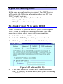
Connecting to the IP Sharing Device
To establish a connection from your PC to the IP Sharing
Device:
1. Start your WEB browser
2. In the Address box, enter "HTTP://" and the IP Address of
the IP Sharing Device, as in the following example:
HTTP://192.168.0.1
3.
You should then see the Home screen. Select the desired
option from the navigation bar.
If you can't connect
If the IP Sharing Device does not respond, check the following:
•
The IP Sharing Device is properly installed, LAN
connections are OK, and it is powered ON.
•
Ensure that your PC and the IP Sharing Device are on
the same network segment. (If you don't have a router,
this must be the case.)
•
Ensure that your PC is using an IP Address within the
range 192.168.0.2 to 192.168.0.254 and thus compatible
with the IP Sharing Device's default IP Address of
17
IP Sharing Device User Guide
192.168.0.1. Also, check that the Network Mask is set to
255.255.255.0
In Windows, the IP Address and Network Mask can be
checked by using Control Panel-Network to check the
Properties for the TCP/IP protocol.
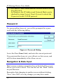
Password
If a password has been set, you will be prompted for a password with the following dialog.
Figure 6: Password Dialog
Leave the User Name blank, and enter the current password.
If no password has been set, you will not see this screen, and
will be taken immediately to the Home screen.
Navigation & Data Input
Most screens contain a navigation bar on the left of the screen
allows you to move about. You can also use the "Back" button
on your Browser.
Remember that changing to another screen without clicking
"Save" does NOT save any changes you may have made.
18
Configuration
HTML uses "forms based input" which means you must send
(submit) the form (by clicking a button) or your data will be
ignored.
19
4
This Chapter explains how to configure the IP
Sharing Device and your LAN for Internet Access.
Overview
To use the IP Sharing Device for Internet Access, the following
operations are required:
•
The IP Sharing Device's Port screen must be configured
with details of the attached modem or ISDN TA, and the
Internet Account to which the modem or ISDN TA will
connect. Details are in this chapter.
•
If you choose not to use the IP Sharing Device's default IP
Address, the LAN settings on the Device screen must be
set correctly. Refer to LAN Settings on page 41 for details.
•
PC's on the LAN may require configuration, as explained
in this chapter.
•
If you have an existing DHCP (Dynamic Host Configuration Protocol) Server, it may require configuration. Details
are in this chapter.
•
If you have a router, its address needs to be entered in the
IP Sharing Device. Refer to LAN Settings on page 41 for
details.
Also, the router itself needs to be configured to use the IP
Sharing Device as its "Default Route" to ensure that pack20
Internet Access
ets are forwarded to the Internet as needed. Check your
Router's documentation to see how this is done.
21
IP Sharing Device User Guide
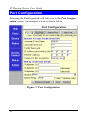
Port Configuration
Selecting the Port hyperlink will take you to the Port Configuration screen. An example screen is shown below.
Figure 7: Port Configuration
22
Internet Access
Operations
•
To enter or change data:
Type in, or select, the required data.
Click Save when finished.
•
To move to Advanced Port or Port Status/Test Screen:
Click the appropriate link at the top of the screen.
Any changes you have made on this screen will NOT be
saved.
•
To retrieve the default values:
Click the Get Defaults button.
Note that this does NOT change the configuration; you
must still use the Save button.
•
To have any Data entered ignored:
Click the Cancel button. Changes since the last Save will
be ignored. The previous data will reappear on screen.
23
IP Sharing Device User Guide
Internet Connection Data
The following data is available from your ISP (Internet Service
Provider).
Account (User) Name
Enter the account name provided
by your ISP. This name will be
used to log in to the ISP’s server.
Account Password
Enter the current password for the
above account.
Verify Password
Re-enter the password to ensure it
is correct.
IP Address
provided by ISP
Enter the IP address assigned to
you by your ISP. If the ISP issues
dynamic IP addresses, leave this
field as 0.0.0.0. (With dynamic IP
addresses, a valid address is
provided upon connection.)
DNS IP Address
The DNS (Domain Name Server)
translates names (e.g. microsoft.com) to IP Addresses.
Enter the DNS IP address supplied or recommended by your
ISP.
Connect to this
Account by
Select Dial up line if you connect
by Modem or ISDN TA.
Select Leased Line(Null modem) if you have a continuous
connection. You can then ignore
the Dial-up Connection section.
24
Internet Access
Dial-up Connection Details
If you are using a dial-up connection, the following data must
also be provided.
Telephone
One (1) number is essential; the other 2 are
optional. Use the format described in your
modem's user manual.
Modem
If your Modem or ISDN TA is listed, simply
select it. Otherwise, try Hayes compatible.
If this does not work, select Other and enter
the required "Initial String" (see below)
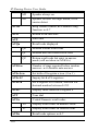
Initial String (AT Commands)
For the IP Sharing Device to function correctly, the modem or
ISDN TA must be configured correctly. The table below shows
the required settings, and the usual AT command.
Setting
Fixed baud rate setting
RTS/CTS flow control
DCD to track the presence of a carrier
DTR off to hang-up modem
DSR always on
Modem to return modem-to-modem
data link speed
AT Command
AT&B1
AT&K3
AT&C1
AT&D2
AT&S0
ATX4
Using these commands, the Initial String would be as follows:
AT&F&B1&K3&C1&D2&S0X4
The first command (AT&F) sets the modem to its factory
defaults. See Appendix B - AT Commands for further details.
25
IP Sharing Device User Guide
PC Configuration
Simple LANs
If your PC is NOT using DHCP and your LAN does NOT
contain a router, check the following TCP/IP settings:
•
IP Address
•
Network Mask
•
Gateway IP Address
•
DNS (Domain Name Server) Address
IP Address
Ensure that each PC has a unique IP Address from the same
address range as the IP Sharing Device's Device IP Address.
For example, if the IP Sharing Device uses the default IP
Address (192.168.0.1) and Network Mask (255.255.255.0), the
PCs must use addresses from 192.168.0.2 to 192.168.0.254.
Network Mask
All PCs, and the IP Sharing Device, must use the same value
for the Network Mask. The default value is 255.255.255.0.
Gateway
Set the PC's Default Gateway Address to the IP Sharing Device's IP address (Device IP Address). The default IP Address
for the IP Sharing Device is 192.168.0.1.
DNS (Domain Name Server) Address
This must match the DNS address entered into the DNS IP
Address field of the IP Sharing Device during configuration.
26
Internet Access
If your PC is using DHCP
In this case, no configuration is required. The DHCP server
will provide the following information when your PC (the
DHCP client) boots up:
• IP Address & matching Network Mask
• Gateway IP Address
• DNS (Domain Name Server)
To check if your PC is using DHCP
Under Windows 95, you can check if your PC is acting as a
DHCP client by using the following procedure. For other
operating systems, check your system documentation.
1. Select Control Panel7Network
2. Select the TCP/IP protocol for your network card.
3. Click Properties-IP Address to see the following screen.
4.
Figure 8: IP Address (Win 95)
If the radio button for "Obtain an IP address automatically" is checked, as shown above, then your PC is acting
as a DHCP client.
27
IP Sharing Device User Guide
DHCP Server Configuration
If you wish to use the DHCP Server in the IP Sharing Device,
refer to DHCP Server on page 43. If you already have a DHCP
Server, check the following:
IP Address
The IP Addresses assigned to PCs must be from the same
address range as the IP Sharing Device's Device IP Address.
For example, if the IP Sharing Device uses the default IP
Address (192.168.0.1) and Network Mask (255.255.255.0), the
PCs must use addresses from 192.168.0.2 to 192.168.0.254.
Network Mask
All PCs, and the IP Sharing Device, need to be using the same
value for the Network Mask. The default value is
255.255.255.0.
Gateway
This depends on whether your LAN has a router:
•
No Router. Set the Default Gateway Address to the IP
address (Device IP Address) assigned to the IP Sharing
Device during configuration. The default IP Address is
192.168.0.1.
•
Router. Do not change the Default Gateway Address.
Instead, configure the router to use the IP Sharing Device
as its "Default Route".
DNS (Domain Name Server) Address
This must match the DNS address entered into the DNS IP
Address field of the IP Sharing Device during configuration.
28
Internet Access
Router Configuration
If your LAN has a router, you must configure the router so that
it passes all IP packets for devices not on the local LAN to the
IP Sharing Device, so that they can be forwarded to the Internet.
This is achieved by configuring the Router so that it uses the IP
Sharing Device as its "Default Route".
Check your Router documentation to see how this is done.
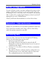
Operation - Internet Access
Simply use your Browser as if you had a permanent connection.
If no connection currently exists, there will be a short delay
while the modem connects to your ISP.
Accessing AOL
To access AOL (America On Line) through the IP Sharing
Device, the following items are necessary :
•
Internet account with an ISP.
The details of this account must be entered in the IP
Sharing Device like any other Internet Access Account, as
explained in this chapter.
•
Version 2.5, 3.0 or later of AOL for Windows communication software.
•
The AOL for Windows software must be configured to use
TCP/IP network access, rather than a dial-up connection.
The configuration process is described below.
29
IP Sharing Device User Guide
AOL for Windows Configuration
Ensure that the IP Sharing Device is configured first, then carry
out the following procedure.
•
Start the AOL for Windows communication software.
Ensure that it is Version 2.5, 3.0 or later.
•
Click the Setup button.
•
Select Create Location, and change the location name
from "New Locality" to "IP Sharing Device".
•
Click Edit Location. Select TCP/IP for the Network field.
(Leave the Phone Number blank.)
•
Click Save, then OK.
Configuration is now complete.
•
Before clicking "Sign On", always ensure that you are
using the "IP Sharing Device" location.
30
5
This Chapter details the settings on the IP
Sharing Device's "Advanced Port Settings"
screen.
Overview
Most users should not have to change these settings. They are
provided for the following situations:
•
You wish to temporarily disable the serial port, so that
Internet access is not possible.
•
Your modem uses non-standard AT commands.
•
Your ISP does not use the standard PPP connection, and
requires a special log-in procedure.
•
You wish to change the "Time-out" period after which an
inactive connection will be terminated.
31
IP Sharing Device User Guide
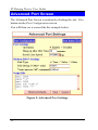
Advanced Port Screen
The Advanced Port Screen is reached by clicking the Adv. Port
button on the Port Configuration screen.
You will then see a screen like the example below.
Figure 9: Advanced Port Settings
32
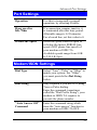
Advanced Port Settings
Port Settings
Operation
Use this to temporarily suspend
operation, by selecting Disable.
Hang up after
Idle Time
If a connection remains inactive, it
is terminated after this time period.
Allowable range is 0-99 minutes.
For a leased line, set this value to 0.
Serial Line Speed
Select the speed which is equal to
or below the fastest SERIAL line
speed (NOT phone line speed) of
your modem or ISDN TA.
Available speeds range from 4.8K
to 230.4.K (bps).
Modem/ISDN Settings
Dial Type
Select "Tone", "Pulse" or "Other" to
match your system. For "Other",
you must provide the Dial String
below.
Dial String
Only required if you are NOT using
Tone or Pulse dialing.
Enter the command (sometimes
called the "Dial Prefix String") your
modem or ISDN TA requires to
precede the phone number.
"Auto Answer Off"
Command
Enter the command string which
turns the "auto-answer" function in
your modem or ISDN TA OFF.
33
IP Sharing Device User Guide
Script File
If your ISP uses a standard PPP connection and authentication,
you do NOT need a script file.
Script files are used to automate the log-in process for ISPs that
use non-standard log-ins or proprietary security measures. For
example, if you connect to the Internet via CompuServe, you
DO need a script file.
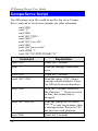
Script File Commands
Three commands, listed below, can be used within a script file.
Note the following points:
•
Items in [ ] are optional, and the [ ] themselves are NOT
used.
•
Strings must be enclosed in double quotes.
•
There must be spaces between commands and parameters
(delay times and strings).
Send [msec] string
Send the characters in string, with a.
msec (milliseconds) delay between
the sending of each character.
Wait msec
Wait for msec milliseconds before
executing the next script line.
Wait [msec] string
Wait for msec milliseconds to receive
the string. If the string is not received
within the specified time, the connection is reset.
If msec is not specified and the string
is not received immediately, an error
condition will arise.
34
Advanced Port Settings
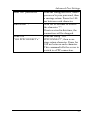
Script File Variables
Eleven string variables can be used within the string above.
These are used to include special characters within the string.
Variable
Description
\a
alert (normally creates a beep)
\b
backspace
\f
form feed
\n
new line
\r
carriage return
\t
horizontal tab
\v
vertical tab
\?
Literal question mark
\’
literal single quotation mark
\”
literal double quotation mark
\\
literal back slash
•
Quote characters are special characters.
•
Because each of these variables starts with a backslash, the
backslash character ( \ ) is also a special character.
As an example, to send the string "User Name" (including the
quotes), the script file entry should be as follows:
send "\"User Name\""
35
IP Sharing Device User Guide
CompuServe Script
The following script file could be used to log on to CompuServe, and can be used as an example for other situations.
wait 3000
send “\r”
wait 3000
send 100 “CIS\r”
wait 3000 “:”
send 100 “user id\r”
wait 3000
send 100 “password\r”
wait 60000 “!”
send 100 “GO PPPCONNECT\r”
Command
Explanation
wait 3000
Pause for 3 seconds
send “\r”
Send the carriage return character.
wait 3000
Pause for 3 seconds
send 100 “CIS\r”
Send the string “CIS”, then a
carriage return character. Pause
for 100 ms between characters.
wait 3000 “:”
Wait for 3 seconds to receive
the character “:” If not received
in time, the connection is
dropped.
send 100 “user id\r”
Send the string user id, where
user id is your log-in name, then
a carriage return. Pause for 100
ms between each character.
wait 3000
Pause for 3 seconds
36
Advanced Port Settings
send 100 “password\r”
Send the string password, where
password is your password, then
a carriage return. Pause for 100
ms between each character.
wait 60000 “!”
Wait for 60 seconds to receive
the character “!”.
If not received in this time, the
connection will be dropped.
Send 100
“GO PPPCONNECT\r”
Send the string “GO
PPPCONNECT”, then a carriage return character. Pause for
100 ms between each character.
This command tells the server to
switch to a PPP connection.
37
IP Sharing Device User Guide
This page was deliberately left blank.
38
6
This Chapter details the options available on
the "Device Settings" screen.
Overview
The Device Settings screen is reached by selecting the Device
link on the navigation bar. An example screen is shown below.
39
IP Sharing Device User Guide
Figure 10: Device Settings Screen
40
Device Options
Device Password
Once a password is entered, it is required in order to change the
device configuration. Passwords are case sensitive and can be
up to 8 alphanumeric characters (no spaces or punctuation).
To create or change the password, enter the required password
in both the New Password and Verify Password input fields.
If the password is lost, a DIP switch setting
is available to clear the password. See the
DIP Switches Table on page 10 for details.
LAN Settings
For most users, the default values for these fields should not
need to be changed.
Device
IP Address
IP address for the IP Sharing Device.
Use the default value of 192.168.0.1 unless:
•
The address is already in use.
•
Your LAN is using a different IP
address range (not 192.168.0.1 to
192.168.0.254). In this case, use an IP
Address from within the address range
used by your LAN.
Router
IP Address
If you have a router, enter its IP Address.
Otherwise, leave this at 0.0.0.0.
Network
Mask
The default value 255.255.255.0 is standard
for small (class "C") networks.
For other networks, enter the Network Mask
value used by PCs on the same LAN segment as the IP Sharing Device.
41
IP Sharing Device User Guide
If you have a router, it is essential that the router
pass all IP packets for devices not on the local
LAN to the IP Sharing Device, so that they can
be forwarded to the Internet.
This is done by configuring the router with the
IP Sharing Device as its "Default Route". Check
your Router documentation to see how this is
done.
42
Device Options
DHCP Server
A DHCP (Dynamic Host Configuration Protocol) server
provides a valid IP address (and the Gateway and DNS addresses) to a DHCP client (PC or device) upon request. The IP
Sharing Device can act as a DHCP server.
To use this feature:
•
The IP Sharing Device must be configured with the following data.
•
The PCs must be configured to act as DHCP clients. This
procedure is explained in the next section.
Configuration Data
Enable/Disable
If Enabled, the IP Sharing Device
will function as a DHCP server. The
default value is Disabled.
Start IP Address
Finish IP Address
The IP Start Address and IP Finish
Address fields set the values used by
the DHCP server.
This range also determines the
number of DHCP clients supported.
(Maximum number of clients is 253.)
DNS IP Address
The IP Addresses provided by your
ISP. Only 1 is essential. Multiple
entries should be entered in the order
you want them accessed. (The first
available DNS will be used.)
The DNS field will display the DNS entered
in the Port Configuration screen.
43
IP Sharing Device User Guide
PC Configuration
To use DHCP, you must also configure your PCs to act as
DHCP clients. Client support for DHCP is provided in Win
95’s TCP/IP stack. The procedure for enabling this is detailed
below.
For operating systems other than Win 95, check your system
documentation.
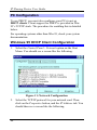
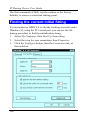
Windows 95 DHCP Client Configuration
1.
Select the Control Panel - Network option on the Start
Menu. You should see a screen like the following.
Figure 11: Network Configuration
2.
44
Select the TCP/IP protocol for your network card. Then
click on the Properties button, and the IP Address tab. You
should then see a screen like the following.
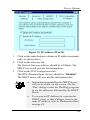
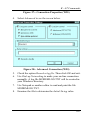
Device Options
Figure 12: IP Address (Win 95)
3.
4.
5.
Click on the radio button to obtain an IP address automatically, as shown above.
Click on the Gateway tab.
The Default Gateway Address should be left blank. The
DHCP server will provide this information.
Click on the DNS Configuration tab
The DNS (Domain Name Server) should be “Disabled”.
The DHCP server will provide this information also.
•
Information provided by the DHCP Server
will not be visible on this screen. Use the
"Run" dialog to start the WinIPcfg program
to see the addresses allocated by the DHCP
Server.
•
To reserve an IP Address for a particular
DHCP client, so that it always receives the
same IP Address, refer to Workstation Data
on page 49.
45
7
This Chapter explains how to configure and
use the IP Sharing Device's "Access Control"
feature.
Overview for SP861A
The optional Access Control feature allows administrators to:
•
Restrict Internet Access by individual workstations.
•
Reserve an IP Address for a particular workstation or
network device.
If you DON'T need to reserve IP Addresses or restrict Internet
Access, you can ignore the Access Control screen.
To apply these features to a particular workstation or network
device, you need to know its Network Adapter Address (Hardware Address).
Access Control Screen
The Access Control screen is accessed from the hyperlink on
the Device Settings screen. This screen allows you to:
•
Identify individual workstations or devices on the LAN, by
naming them and entering their Network Adapter Address.
46
Access Control
•
Reserve an IP Address for the workstation or network
device, so that the DHCP Server in the IP Sharing Device
always gives them the same IP Address (optional).
•
Impose restrictions on the Internet Access enjoyed by the
workstation (optional).
An example screen is shown below.
Figure 13: Access Control Screen
Note that the Name drop-down box lists all Workstations
previously entered. If none have been entered, this box will be
empty.
47
IP Sharing Device User Guide
Operations
•
To Add a New Workstation:
Ignore the drop-down box, click the Clear Form button,
and enter the Workstation details in the fields provided.
Click Add when finished.
•
To Delete an Existing Workstation:
Select the Workstation from the drop-down box, click Get
Details to view the information and confirm that this is the
correct Workstation, then click the Delete button.
•
To Change an Existing Workstation's Details:
Select the Workstation from the drop-down box, click Get
Details to view their information, then change any fields
you wish.
Click Update when finished.
•
To Generate a List of all Workstations:
Just click on the List All button.
48
Access Control
Workstation Data
Workstation
Name
Enter a name to identify this workstation.
Network Adapter
Address
Hardware address for this workstation or LAN device. You can use the
Windows "Winipcfg" program or
your LAN management program to
find this address.
Reserve entry in
DHCP Table
Check this if you wish to reserve an
IP address for this workstation. This
is useful if you have to provide the IP
Address for other programs or users
If this is left unchecked, the following entry can be ignored.
Reserved
IP Address
This relates to the entry above. Enter
the reserved address here. This
MUST be within the range used by
the DHCP server (set on the "Device"
screen).
Access
Restrictions
Select the desired level of access for
this workstation. The available
options are:
•
No restrictions
•
Block all access (No Internet
Access)
•
E-Mail only
49
IP Sharing Device User Guide
Overview for SP862B/864B
The Access Control feature allows administrators to restrict
Internet Access by individual workstations. The process uses
"Packet Filtering" to block or discard data packets. By default,
no packets are blocked or discarded.
To use this feature:
•
Set the desired restrictions on the "Everyone" group. By
default, all PCs are in the "Everyone" group unless explicitly moved to another group, using the Workstation screen.
•
Set the desired restrictions on the other groups ("Group 1",
"Group 2", etc ) as needed.
•
For each Workstation you wish to move from the "Everyone" group, enter their details on the Workstation screen,
and assign them to the desired group
You can limit Internet access for ALL PCs
without entering ANY workstation data.
Simply apply the desired restrictions to the
"Everyone" group.
It is also possible to define your own packet filters, and use
these filters in addition to the pre-defined filters. Defining your
own filters is optional.
50
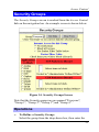
Access Control
Security Groups
The Security Groups screen is reached from the Access Control
link on the navigation bar. An example screen is shown below.
Figure 14: Security Groups Screen
Note that the Security groups are pre-named "Everyone",
"Group 1", "Group 2", "Group 3", and "Group 4".
Operations
•
To Define a Security Group:
Select the group from the drop-down box, then enter the
51
IP Sharing Device User Guide
required data. If necessary, click Clear Form to remove
the existing information shown on screen.
Click the Save button when finished.
•
To Change Access for an Existing Group:
Select the group from the drop-down box, click Get Details to view their information, then change any fields you
wish.
Click Save when finished.
•
To Assign Workstations to a Security Group
All Workstations are automatically in the "Everyone"
group. Use the Workstations screen to move them to another group if required.
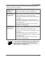
Data
The following data is required.
Internet Access for this Group
There are 3 options:
•
No restrictions - No packets are blocked. Use this to
create an "Unlimited Access" group, or to temporarily remove restrictions from a group.
•
Block all Access - Groups members cannot access the
Internet at all. Use this to create the most restrictive group.
•
Use Packet Filter Table below - Use this to define
intermediate levels of access. Using the Packet Filter table
gives you fine control over Internet access.
Packet Filter Table
Simply select the items you wish to block. You can choose
from the pre-defined filters in the Applications to Block column,
52
Access Control
or your own filters in the TCP Packets to Discard and UPD
Packets to Discard column.
Applications
to Block
Any items checked will be blocked. Users
will not be able to use the application.
TCP Packets
to Discard
This lists any TCP filters you have defined
on the Administrator Defined Filters
screen. If no filters have been defined, this
is empty.
Multiple items can be selected (or deselected) by holding down the Ctrl key while
selecting items.
Selected items can NOT be accessed by
members of this group.
UPD Packets
to Discard
This lists any UDP filters you have defined
on the Administrator Defined Filters
screen. If no filters have been defined, this
is empty.
Multiple items can be selected (or deselected) by holding down the Ctrl key while
selecting items.
Selected items can NOT be accessed by
members of this group.
If you have not defined your own filters, but
wish to do so, refer to "Administrator Defined Filters" on page 56.
53
IP Sharing Device User Guide
Workstations
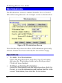
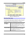
The Workstations screen is reached from the Access Control
link on the navigation bar. An example screen is shown below.
Figure 15: Workstations Screen
Note that the drop-down box lists all Workstations previously
entered. If none have been entered, this box will be empty.
Operations
•
To Add a New Workstation:
Ignore the drop-down box, click the Clear Form button,
and enter the Workstation details in the fields provided.
Click Add when finished.
•
To Delete an Existing Workstation:
Select the Workstation from the drop-down box, click Get
Details to view the information and confirm that this is the
correct Workstation, then click the Delete button.
54
Access Control
•
To Change an Existing Workstation's Details:
Select the Workstation from the drop-down box, click Get
Details to view their information, then change any fields
you wish.
Click Update when finished.
•
To Generate a List of all Workstations:
Just click on the List All button.
Data
Workstation
Name
Enter a name to identify this workstation.
Network Adapter
Address
Hardware address for this workstation. You can use the Windows
"Winipcfg" program or your LAN
management program to find this
address.
Reserve entry in
DHCP Table
Check this if you wish to reserve an
IP address for this workstation. This
is useful if you have to provide the IP
Address for other programs or users
If this is left unchecked, the following entry can be ignored.
Reserved
IP Address
This relates to the entry above. Enter
the reserved address here. This
MUST be within the range used by
the DHCP server (set on the "Device"
screen).
55
IP Sharing Device User Guide
Security Group
Select the security group for this
workstation. If you only wish to
reserve an IP Address, and are not
using the security (access control)
features, simply leave this at "Everyone".
Administrator Defined Filters
The Administrator Defined Filters screen is reached from the
Access Control link on the navigation bar. An example screen
is shown below.
Figure 16: Administrator Defined Filters
56
Access Control
This screen allows you to define packet filters. After you
define packet filters, they will appear on the "Security Groups"
screen. You can select them, as well as the pre-defined filters,
when applying restrictions to a Security Group.
Data
TCP Packets
Define the packets you wish to be filtered out, by entering the
following data.
Name
Enter a descriptive name for this entry.
Port No.
Enter an integer representing the Port Number
for this type of packet. A Network Analyzer or
Packet Sniffer can be used to determine the
correct port number.
UDP Packets
Define the packets you wish to be filtered out, by entering the
following data.
Name
Enter a descriptive name for this entry.
Port No.
Enter an integer representing the Port Number
for this type of packet. A Network Analyzer or
Packet Sniffer can be used to determine the
correct port number.
57
IP Sharing Device User Guide
Overview for SP862B/864B
The Access Control feature allows administrators to restrict
Internet Access by individual workstations. The process uses
"Packet Filtering" to block or discard data packets. By default,
no packets are blocked or discarded.
To use this feature:
•
Set the desired restrictions on the "Everyone" group. By
default, all PCs are in the "Everyone" group unless explicitly moved to another group, using the Workstation screen.
•
Set the desired restrictions on the other groups ("Group 1",
"Group 2", etc ) as needed.
•
For each Workstation you wish to move from the "Everyone" group, enter their details on the Workstation screen,
and assign them to the desired group
You can limit Internet access for ALL PCs
without entering ANY workstation data.
Simply apply the desired restrictions to the
"Everyone" group.
It is also possible to define your own packet filters, and use
these filters in addition to the pre-defined filters. Defining your
own filters is optional.
58
Access Control
Security Groups
The Security Groups screen is reached from the Access Control
link on the navigation bar. An example screen is shown below.
Figure 17: Security Groups Screen
Note that the Security groups are pre-named "Everyone",
"Group 1", "Group 2", "Group 3", and "Group 4".
Operations
•
To Define a Security Group:
Select the group from the drop-down box, then enter the
59
IP Sharing Device User Guide
required data. If necessary, click Clear Form to remove
the existing information shown on screen.
Click the Save button when finished.
•
To Change Access for an Existing Group:
Select the group from the drop-down box, click Get Details to view their information, then change any fields you
wish.
Click Save when finished.
•
To Assign Workstations to a Security Group
All Workstations are automatically in the "Everyone"
group. Use the Workstations screen to move them to another group if required.
Data
The following data is required.
Internet Access for this Group
There are 3 options:
•
No restrictions - No packets are blocked. Use this to
create an "Unlimited Access" group, or to temporarily remove restrictions from a group.
•
Block all Access - Groups members cannot access the
Internet at all. Use this to create the most restrictive group.
•
Use Packet Filter Table below - Use this to define
intermediate levels of access. Using the Packet Filter table
gives you fine control over Internet access.
Packet Filter Table
Simply select the items you wish to block. You can choose
from the pre-defined filters in the Applications to Block column,
60
Access Control
or your own filters in the TCP Packets to Discard and UPD
Packets to Discard column.
Applications
to Block
Any items checked will be blocked. Users
will not be able to use the application.
TCP Packets
to Discard
This lists any TCP filters you have defined
on the Administrator Defined Filters
screen. If no filters have been defined, this
is empty.
Multiple items can be selected (or deselected) by holding down the Ctrl key while
selecting items.
Selected items can NOT be accessed by
members of this group.
UPD Packets
to Discard
This lists any UDP filters you have defined
on the Administrator Defined Filters
screen. If no filters have been defined, this
is empty.
Multiple items can be selected (or deselected) by holding down the Ctrl key while
selecting items.
Selected items can NOT be accessed by
members of this group.
If you have not defined your own filters, but
wish to do so, refer to "Administrator Defined Filters" on page 56.
61
IP Sharing Device User Guide
Workstations
The Workstations screen is reached from the Access Control
link on the navigation bar. An example screen is shown below.
Figure 18: Workstations Screen
Note that the drop-down box lists all Workstations previously
entered. If none have been entered, this box will be empty.
Operations
•
To Add a New Workstation:
Ignore the drop-down box, click the Clear Form button,
and enter the Workstation details in the fields provided.
Click Add when finished.
•
To Delete an Existing Workstation:
Select the Workstation from the drop-down box, click Get
Details to view the information and confirm that this is the
correct Workstation, then click the Delete button.
62
Access Control
•
To Change an Existing Workstation's Details:
Select the Workstation from the drop-down box, click Get
Details to view their information, then change any fields
you wish.
Click Update when finished.
•
To Generate a List of all Workstations:
Just click on the List All button.
Data
Workstation
Name
Enter a name to identify this workstation.
Network Adapter
Address
Hardware address for this workstation. You can use the Windows
"Winipcfg" program or your LAN
management program to find this
address.
Reserve entry in
DHCP Table
Check this if you wish to reserve an
IP address for this workstation. This
is useful if you have to provide the IP
Address for other programs or users
If this is left unchecked, the following entry can be ignored.
Reserved
IP Address
This relates to the entry above. Enter
the reserved address here. This
MUST be within the range used by
the DHCP server (set on the "Device"
screen).
63
IP Sharing Device User Guide
Security Group
Select the security group for this
workstation. If you only wish to
reserve an IP Address, and are not
using the security (access control)
features, simply leave this at "Everyone".
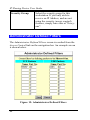
Administrator Defined Filters
The Administrator Defined Filters screen is reached from the
Access Control link on the navigation bar. An example screen
is shown below.
Figure 19: Administrator Defined Filters
64
Access Control
This screen allows you to define packet filters. After you
define packet filters, they will appear on the "Security Groups"
screen. You can select them, as well as the pre-defined filters,
when applying restrictions to a Security Group.
Data
TCP Packets
Define the packets you wish to be filtered out, by entering the
following data.
Name
Enter a descriptive name for this entry.
Port No.
Enter an integer representing the Port Number
for this type of packet. A Network Analyzer or
Packet Sniffer can be used to determine the
correct port number.
UDP Packets
Define the packets you wish to be filtered out, by entering the
following data.
Name
Enter a descriptive name for this entry.
Port No.
Enter an integer representing the Port Number
for this type of packet. A Network Analyzer or
Packet Sniffer can be used to determine the
correct port number.
65
IP Sharing Device User Guide
66
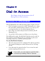
This Chapter details the operation of the IP
Sharing Device's Dial-in feature.
Overview for SP862B/864B
The IP Sharing Device's dial-in feature allows remote users to:
•
Dial the modem connected to theIP Sharing Device, using
the same PPP communication software (e.g. Dial-up Networking) that they use for dial-in Internet access.
•
Have their user name and password verified by the IP
Sharing Device.
•
Access the LAN resources as if they were a local user.
For additional security, the dial-back function can be used. In
this situation, the IP Sharing Device will hang-up the user's
incoming connection, and then call them back.
To use the Dial-in Feature:
•
The relevant port must be configured for dial-in operation.
The required settings are on the Advanced Port Settings
screen.
•
User data must be entered on the Users screen for each
person requiring dial-in access.
If you wish, you can reserve a port for dialin access by enabling "Dial-in" and dis67
IP Sharing Device User Guide
abling "Internet Access".
Port Configuration for Dial-In
To use dial-in access, the relevant port must have the following
data entered on the Advanced Port Settings screen. This screen
is reached by the Adv. Port button on the Port Configuration
screen.
Dial-in
If checked, this port is available for
dial-in access. Otherwise, any attempt
to dial-in will be blocked.
Idle Timeout
If a dial-in connection remains
inactive, it is terminated after this
time period. Allowable range is 0-99
minutes.
Dial-in PPP Link
Select the desired option. CHAP is
more secure. If it is selected, the dialin clients must also support CHAP in
order to connect.
PAP is less secure, but more common.
Warning! If you choose "None", no
User Name/Password authentication
is performed on dial-in
68
Dial-in Access
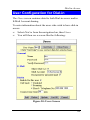
User Configuration for Dial-in
The Users screen contains data for both Dial-in access and/or
E-Mail Account sharing.
To enter information about the users who wish to have dial-in
access:
•
Select Dial-in from the navigation bar, then Users.
•
You will then see a screen like the following:
Figure 20: Users Screen
69
IP Sharing Device User Guide
Note that existing users are listed in a drop-down box. If no
users have been entered, this box will be empty.
This screen is also used provide user information for "E-Mail
Account Sharing". For Dial-in use only, simply ignore the "EMail" section of the screen.
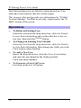
Operations
•
To Delete an Existing User:
Select the user from the drop-down box, click Get Details
to view their information and confirm that this is the correct user, then click the Delete button.
•
To Change an Existing User's Details:
Select the user from the drop-down box, click Get Details
to view their information, then change any fields you wish.
Click Update when finished.
•
To Add a New User:
Ignore the drop-down box, click the Clear Form button,
and enter the user details in the fields provided.
Click Add when finished.
•
To Generate a List of all Users:
Just click on the List All button.
70
Dial-in Access
User Data
For each user requiring Dial-in access, the following data is
required.
General
User Name
Existing users are shown in a drop-down list.
You can select a user from this list to change
their details.
When adding a new user, the drop-down list
is ignored; just enter the details for the new
user.
Note the limitations on user names:
• Multiple words are NOT allowed
Password
•
Punctuation and special characters
should NOT be used.
•
User names are case insensitive (case is
ignored).
The password for the current user. Passwords are case sensitive.
71
IP Sharing Device User Guide
Dial-in
Enable for
this user
Use this to suspend or enable dial-in access.
Call Back
Disabled:- User can simply dial-in; the
device will not hang-up and call back.
Roaming:- After providing their name and
password, the user is prompted for the callback number.
Fixed:- The number entered in the Tel field
is always used as the call-back number.
Connect
Time limit
After this time period, the user is disconnected. Allowable values are 0 (default) to
999 minutes. Zero means no time limit.
Remote User Configuration
The remote user can use the same dial-up software they use for
Internet access. They should check the following:
•
Their program must dial the telephone number of the
modem connected to the port used for dial-in access.
•
When prompted for user name and password, they must
enter the name and password stored in the IP Sharing
Device.
Once connected, they can access LAN resources as they
normally would. They will appear to other LAN devices as a
normal PC on the LAN, using the IP Address allocated by the
IP Sharing Device.
72
73
89
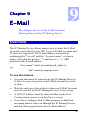
This Chapter the use of the E-Mail Account
Sharing feature of the IP Sharing Device.
Overview
The IP Sharing Device allows many users to share the E-Mail
Account(s) provided by your ISP. Up to 4 E-Mail accounts and
50 users are supported. The E-mail address is formed by
combining the "User id" and the "Account name", as shown
below. Note that the quotes (" ") and braces ( < > ) ARE
included in the E-mail address.
"user_name"<mail_account@mail_address>
e.g.
"jim"<[email protected]>
To use this feature:
•
Account data must be entered into the IP Sharing Device's
E-Mail Account screen for each E-Mail account you wish
to share.
•
Data for each user who wishes to share an E-Mail Account
must be entered in the IP Sharing Device's Users screen
•
A DNS IP Address must be entered either on the Port
Configuration screen or on the Device screen.
•
Users must configure their E-Mail program so that their
incoming mail is retrieved through the IP Sharing Device,
and that other people know their E-Mail address.
74
E-Mail
Each of these operations is described in the following section.
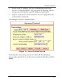
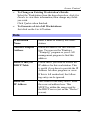
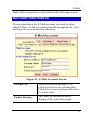
Account Information
To enter data about the E-Mail accounts you wish to share,
select E-Mail - E-Mail Accounts from the navigation bar. You
will then see a screen like the following:
Figure 21: E-Mail Accounts Screen
Account No.
Select the desired account (1..4)
Click Get Data to see existing data.
Click Clear Form to prepare the form
for a new entry.
Enable Sharing
This must be checked to allow
sharing of the selected account.
75
IP Sharing Device User Guide
POP3 Mail Server
Address
Enter the address of the POP3 Mail
Server, as provided by your ISP.
POP3 Mail Server
Account Name
This name is provided by your ISP.
Using a Department name (e.g. Sales)
is recommended.
Password
The password for the above account.
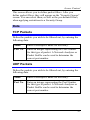
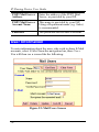
User Information
To enter information about the users who wish to share E-Mail
accounts, select E-Mail from the navigation bar, then Users.
You will then see a screen like the following:
Figure 22: Mail Users Screen
76
E-Mail
Note that existing users are listed in a drop-down box. If no
users have been entered, this box will be empty. Ignore this
drop-down list when adding a new user.
Operations
•
To Delete an Existing User:
Select the user from the drop-down box, click Get Details
to view their information and confirm that this is the correct user, then click the Delete button.
•
To Change an Existing User's Details:
Select the user from the drop-down box, click Get Details
to view their information, then change any fields you wish.
Click Update when finished.
•
To Add a New User:
Ignore the drop-down box, click the Clear Form button,
and enter the user details in the fields provided.
Click Add when finished.
•
To Generate a List of all Users:
Just click on the List All button.
User Data
For each user wishing to share an E-Mail account, the following data is required.
General
User Name
When adding new users, ignore the dropdown list, and enter the new name here.
Note the limitations on user names:
• Multiple words are NOT allowed
77
IP Sharing Device User Guide
Password
•
Punctuation and special characters
should NOT be used.
•
User names are case insensitive (case is
ignored).
The password for the current user. This
password will be entered into their E-Mail
program. Passwords are case sensitive.
E-Mail
Mail Account
Select the E-Mail account that this user
is going to share. Account information
should have been previously entered.
Set as Recipient
for
Unrouted Mail
If this setting is ON (Checked), then
when this user retrieves their E-mail,
they will also receive all E-mail sent to
this mail account when there is no user
name, or the user name is invalid.
More than one user can be set.
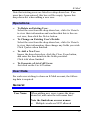
DNS Address
A DNS (Domain Name Server) Address is required to enable
the IP Sharing Device to locate the Mail Server.
This address is on the Port Configuration screen and on the
Device screen.
Ensure that the DNS Address has been entered.
78
E-Mail
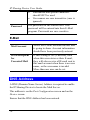
E-Mail Program Configuration
Each user wishing to share an E-Mail account must configure
their E-Mail program with the following data.
Name
The User Name entered in the E-Mail
User Screen of the IP Sharing Device.
E-Mail Address
The full name of the E-Mail account
which is being shared, as provided by
your ISP.
e.g. [email protected]
SMTP Server
(Outgoing Mail)
The SMTP Server address as provided
by your ISP
POP3 Server
(Incoming Mail)
Set this to the IP Address of the IP
Sharing Device
POP3 Account
The User Name entered in the E-Mail
User Screen of the IP Sharing Device.
Password
The user password entered in the User
screen of the IP Sharing Device.
•
Note that outgoing E-mail is sent normally; only incoming
E-mail is processed by the IP Sharing Device.
•
If some of your incoming E-mail does not include your
name, and thus becomes "Unrouted Mail", ask those senders to record your E-Mail Address in the following format.
Note that quotes ( " " ) and braces ( < > ) ARE typed in.
"user_name"<mail_account@mail_address>
e.g.
"jim"<[email protected]>
Your printed E-Mail Address (e.g. on your business card)
should also show your E-Mail address in the format above.
79
IP Sharing Device User Guide
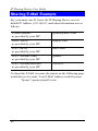
Sharing E-Mail Example
Say your name was B. Jones, the IP Sharing Device uses its
default IP Address (192.168.0.1) and other information was as
follows:
E-Mail Address
as provided by your ISP
[email protected]
SMTP Server
as provided by your ISP
smtp09.com
POP3 Server
as provided by your ISP
ms02.com
POP3 Account Name
as provided by your ISP
greatco
POP3 Account password
as provided by your ISP
9087654
To share this E Mail Account, the entries on the following page
would have to be made. Your E-Mail Address would become:
"bjones"<[email protected]>
80
E-Mail
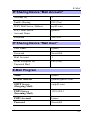
IP Sharing Device "Mail Account"
Account No.
1
Enable Sharing
ON (Yes)
POP3 Mail Server Address
ms02.com
POP3 Mail Server
Account Name
greatco
Password
9087654
IP Sharing Device "Mail User"
User Name
bjones
Password
Secret064
Mail Account
1
Set as Recipient for
Unrouted Mail
ON (Yes)
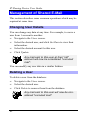
E-Mail Program
Name
bjones
E-Mail Address
[email protected]
SMTP Server
(Outgoing Mail)
smtp09.com
POP3 Server
(Incoming Mail)
192.168.0.1
POP3 Account
bjones
Password
Secret064
81
IP Sharing Device User Guide
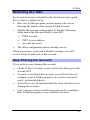
Management of Shared E-Mail
This section describes some common operations which may be
required at some time.
Changing User Details
You can change any data at any time. For example, to move a
user from 1 account to another:
•
Navigate to the Users screen.
•
Select the desired user, and click Get Data to view their
information.
•
Select the desired account for this user.
•
Click Update
Any mail sent to this user at their "old"
account will now be considered "unrouted
mail".
You can modify any user data in a similar fashion.
Deleting a User
To delete a user from the database:
•
Navigate to the Users screen.
•
Select the desired user.
•
Click Delete to remove them from the database.
Any mail sent to this user will now be considered "unrouted mail".
82
E-Mail
Retrieving ALL Mail
If you wish to retrieve all mail for the shared account, regardless of who it is addressed to:
•
Run your E-Mail program, and navigate to the screen
showing the details of the shared E-Mail account.
•
Modify the account configuration so that the following
fields match the data provided by your ISP:
•
•
POP3 account
•
POP3 Server address
•
Account password
The other configuration data is already correct.
When you retrieve your mail with these settings, you will
receive all the E-mail sent to this account.
Stop Sharing the Account
If you wish to cease sharing this account:
•
On the E-Mail Accounts screen, set Enable Sharing for this
account OFF.
•
To retrieve mail from this account, you will now have to
configure your E-Mail program to access the account directly, as described above.
•
You will receive all mail intended for users who have been
sharing this account.
•
Users who previously used this account need to configure
their E-Mail programs to use a different account.
83
IP Sharing Device User Guide
This Chapter explains the Routing features of
the IP Sharing Device.
Overview
While the IP Sharing Device includes a standard routing table,
this feature can be completely ignored if you do not have a
router in your LAN.
If you DO have a router, it is necessary to configure BOTH the
Router and the Routing table in the IP Sharing Device correctly,
as described in the following sections.
See page 88 for an example of configuring
both the IP Sharing Device and the Router.
IP Sharing Device Configuration
The routing table is accessed by the Routing link on the navigation bar. This link appears only on the Device Screen. An
example screen is shown below.
84
E-Mail
Figure 23: Routing Screen
Routing Table Data
An entry in the routing table is required for each LAN segment
on your Network, other than the segment to which this device
is attached. The data in the Routing Table is as follows.
Destination
IP Address
The network address of the remote LAN
segment. For standard class "C" LANs,
the network address is the first 3 fields of
this Destination IP Address. The 4th (last)
field can be left at 0.
Network Mask
The Network Mask used on the remote
LAN segment. For class "C" networks,
the standard Network Mask is
255.255.255.0
85
IP Sharing Device User Guide
Gateway
IP Address
The IP Address of the Router on the
LAN segment to which this device is
attached. (NOT the router on the remote
LAN segment.)
Metric
The number routers which must be
navigated to reach the remote LAN
segment. The default value is 1.
Routing tables normally have an "Interface"
field. Here, all entries are for the LAN Interface,
so this field is absent.
Router Configuration
It is essential that all IP packets for devices not on the local
LAN be passed to the IP Sharing Device, so that they can be
forwarded to the Internet. To achieve this, the Routers must be
configured to use the IP Sharing Device as the Default Route or
Default Gateway.
Local Router
The local router is the Router installed on the same LAN
segment as the IP Sharing Device. This router requires that the
Default Route is the IP Sharing Device itself. Typically, routers
have a special entry for the Default Route. It should be configured as follows.
86
E-Mail
Destination IP Address
Normally 0.0.0.0, but check
your router documentation.
Network Mask
Normally 0.0.0.0, but check
your router documentation.
Gateway IP Address
The IP Address of the IP
Sharing Device.
Metric
1
Other Routers
Other routers must use the IP Sharing Device's Local Router as
the Default Route. The entries will be the same as the IP
Sharing Device's local router, with the exception of the Gateway IP Address.
•
For a router with a direct connection to the IP Sharing
Device's local Router, the Gateway IP Address is the address of the IP Sharing Device's local router.
•
For routers which must forward packets to another router
before reaching the IP Sharing Device's local router, the
Gateway IP Address is the address of the intermediate
router.
87
IP Sharing Device User Guide
Routing Example
R o ute r A
(192.168.1.80)
S e g m ent 1
(192.168.1.xx)
(192.168.0.100)
S eg m e nt 0
(192.168.0.xx)
IP Sha rer
R oute r B
(192.168.1.90)
(192 .168.0.1)
(19 2.168.2.70)
S e g m ent 2
(192.168.2.xx)
Figure 24: Routing Example
For the LAN shown above, with 2 routers and 3 LAN segments,
the required entries would be as follows.
For the IP Sharing Device's Routing Table
The IP Sharing Device requires 2 entries as follows.
Entry 1 (Segment 1)
Destination IP Address
192.168.1.0
Network Mask
255.255.255.0
(Standard Class C)
Gateway IP Address
192.168.0.100 (IP Sharing
Device's local Router)
Entry 2 (Segment 2)
Destination IP Address
192.168.2.0
Network Mask
255.255.255.0
Gateway IP Address
192.168.0.100
88
E-Mail
For Router A's Default Route
Destination IP Address
0.0.0.0
Network Mask
0.0.0.0
Gateway IP Address
192.168.0.1
(IP Sharing Device's IP
Address)
For Router B's Default Route
Destination IP Address
0.0.0.0
Network Mask
0.0.0.0
Gateway IP Address
192.168.1.80
(IP Sharing Device's local
router)
89
11
This Chapter explains the Status and Monitoring features of the IP Sharing Device.
Overview
The IP Sharing Device allows you to connect to it through the
LAN while it is operating, and view the device status, and
monitor the operation of each port.
Status Screen
The Status screen can be reached with the hyperlink on the
navigation bar. An example screen is shown below.
90
Status and Monitoring
Figure 25: Status Screen
91
IP Sharing Device User Guide
Data
Device
Firmware Version
Version of the firmware (embedded
software) which is currently installed.
Technical support staff may ask for
this information.
Physical Address
The hardware address of this device.
Hardware ID
The hardware ID is used by the
manufacturer for identification.
LAN
IP Address
The IP Address of this device.
Network Mask
The Network Mask value stored in
this device. This must match the
Network Mask for the LAN segment
to which this device is connected.
Router IP Address
The IP Address of the router. If there
is no router, this will show 0.0.0.0.
DHCP
Status of the DHCP Server function.
("Enabled" or "Disabled")
E-Mail Sharing
If E-mail sharing is used on any Email account, this will display "ON".
Otherwise, the status will be "OFF".
Port
Possible values are "Enabled" or
"Disabled", as set on the Advanced
Port Settings screen.
92
Status and Monitoring
DHCP Table
This table will be empty unless DHCP has been "Enabled". If
DHCP is being used, this table lists the devices which have
been allocated IP Addresses by the DHCP server function.
Only IP Addresses in use will be listed.
IP Address
The IP Address which has been
allocated by the DHCP server to the
other device.
Physical Address
The Physical Address (Hardware
Address) of the device which has
been allocated a IP Address.
Status
Possible Status values are "Leased"
(the IP Address is allocated to the
device shown) or "Reserved" (the IP
Address is not available).
93
IP Sharing Device User Guide
Port Status/Test Screen
This screen is reached by clicking the Port Status/Test link on
the Port Configuration or Advanced Port Settings screens.
An example screen is shown below.
Figure 26: Port Status & Test
94
Status and Monitoring
Operation
Select the action you wish to perform, by clicking on the
appropriate button.
•
Hang-up will hang up the modem, if it is currently connected
•
Dial will dial the ISP, if not currently connected.
•
Clear Log will remove all data in the Log window, making new data easier to read.
•
Refresh will update the display with the current data.
Status Data
Physical Link
If operating, the link will show ON.
This means the modem was able to
connect to the number dialed.
PPP Link
If ON, a PPP connection was successfully negotiated.
Serial Line Speed
The connection speed between this
device and the modem.
Phone Line Speed
The connection speed over the phone
line, between your modem and the
number dialed.
PPP IP Address
The IP Address used by this device.
This address is provided by the ISP
on connection.
95
IP Sharing Device User Guide
Modem Log
This shows the commands sent to the modem, and any status
messages returned by the modem. Note that this is not "live";
you must click Refresh to update the information.
The following table shows the more common messages, and
their meaning.
Message
Description
Dialing
Dialing the ISP
Try to establish
physical connection.
The device is trying to connect with
the ISP, using the modem.
Busy error
The number dialed was busy.
Physical line is
connected
Physical connection to ISP has been
established.
CONNECT nnnnnn
Physical connection was successful;
nnnnnn indicates the speed of the
serial link as currently configured.
Max phone line speed
nnnnnn bps
nnnnnn is the maximum speed of
the modem, according to the current
configuration.
DCD low,
DSR low
Physical line break, connection lost.
send “-----“
“AT” commands sent to the modem
are displayed as they are sent.
Commands in the Script file are
also displayed as they are executed.
wait “-----“
Start PPP
96
Having established a physical
connection, a PPP connection is
now being established.
Status and Monitoring
PPP up fail
The PPP connection could not be
established.
PPP up successfully
The PPP connection was established successfully.
Stop PPP
The PPP connection was terminated. This will occur at the end of
a session, or an error condition.
Try to hang up
Attempting to get the modem to
hang up.
Time out
There was no response from the
modem
No carrier
No answer
The number dialed did not answer.
Idle timer expires
The time period (in the configuration) to disconnect if the link is not
used is up.
No dial tone
The modem could not obtain a dial
tone.
Set baudrate nnnn
The serial line speed is being set to
the speed set in the configuration.
Normal Operation
The following sequence of messages is typical of normal
operation.
send “ATDT 0123456789”
CONNECT 115200
max phone line speed 28800 bps
physical line is connected
start PPP
ppp up successfully
97
IP Sharing Device User Guide
Error Conditions
The following table shows messages which indicate an error
condition, and the suggested corrective action.
No dial tone
The modem could not obtain a dial tone.
Check your connections on the phone line
and the modem.
Busy error
The number dialed was busy. Check that
the number is correct. If it is, try dialing
later. If this occurs regularly, check with
your ISP.
DCD low
DSR low
The connection was lost. This could
indicate a bad line or poor connection.
Normally, if a connection is lost, it will
automatically be re-established.
PPP up fail
The ISP rejected the attempt at connection.
Check that your username and password is
correct. If it is, check with your ISP to see
why the connection is being rejected.
Time out
No response. Check that the modem is ON
and properly connected to the IP Sharing
Device.
No carrier
No answer
There was no response from the phone
number dialed. Check that the phone
number is correct, and the modem is
working. If both of these are OK, check
with your ISP.
98
Status and Monitoring
This page was deliberately left blank.
99
A
This Appendix covers the most likely problems
and their solutions.
Overview
This chapter covers some problems that may arise and possible
solutions to them. If you follow the suggested steps and the IP
Sharing Device still does not function properly, contact your
dealer for further advice.
Problems
Problem 1
Can’t connect to the IP Sharing Device to
configure it.
Solution 1
Check the following:
•
The IP Sharing Device is properly
installed, LAN connections are OK, and
it is powered ON.
•
Ensure that your PC and the IP Sharing
Device are on the same network segment. (If you don't have a router, this
must be the case.)
100
A - Troubleshooting
•
Ensure that your PC is using an IP
Address within the range 192.168.0.2 to
192.168.0.254 and thus compatible with
the IP Sharing Device's default IP Address of 192.168.0.1.
In Windows, you can check your PC's
IP Address by using Control PanelNetwork to check the Properties for the
TCP/IP protocol.
Problem 2
When I enter a URL or IP address I get a
time out error.
Solution 2
A number of things could cause this. Try the
following troubleshooting steps.
1. If this is first time you have used your
browser, ensure that your workstations
IP settings are correct, including IP address, default gateway and DNS.
2. Ping the IP Sharing Device. Use the
“Run” command to enter the following
command:
Ping xxx.xxx.xxx.xxx
where xxx.xxx.xxx.xxx is the IP address
assigned to the IP Sharing Device’s
LAN interface.
3. If the ping command fails, check that
the IP Sharing Device is connected and
ON. If it is connected and on, there is a
problem with your LAN.
4. Check that Port is "Enabled" (Advanced
Port Settings). If not, you need to use
the HTML program to establish a connection.
5. Run your Browser and connect to the IP
101
IP Sharing Device User Guide
6.
Sharing Device.
Switch to the Status screen, and examine the Log. For details of the Log
messages, see page 96.
Problem 3:
My Modem/ISDN TA is working fine with
a dial-up connection through the serial
port. How do I find what "Initial String"
it is using?
Solution 3
Use the procedure described in Finding the
current Initial String on page 106.
Problem 4
Data Transmissions are very slow.
Solution 4
Check and ensure that the Initial String is
configured to RTS/CTS flow control.
Problem 5
Some applications do not run properly
when using the IP Sharing Device.
Solution 5
The IP Sharing Device processes the data
passing through it, so it is not transparent.
Some programs may have limited functionality when used with the IP Sharing Device.
The number of supported applications is
being expanded as rapidly as possible. The
following applications and protocols are
supported by firmware V5.0:
Telnet, FTP, HTTP, ping
POP/SMTP, Archie, NNTP
TFTP, IRC, Gopher
DNS, SNMP, Real Audio
102
A - Troubleshooting
103
IP Sharing Device User Guide
This page was deliberately left blank.
104
B
Required Settings
For the IP Sharing Device to function correctly, the modem or
ISDN TA must be set as follows.
Setting
AT Command
Fixed baud rate setting
AT&B1
RTS/CTS flow control
AT&K3
DCD to track the presence of a carrier
AT&C1
DTR off to hang-up modem
AT&D2
DSR always on
AT&S0
Modem to return modem-to-modem
data link speed
ATX4
(see Note below)
• For some Mircocom and other modems, the
“ATX4” command is not sufficient - a “W2”
command (no “AT”) must be used as well.
• For an ISDN TA, the above commands may
not be sufficient. Please check the following
section and your ISDN TA's user manual.
For a modem which uses the standard AT commands shown
above, the Initial String would look like the following:
AT&F&B1&K3&C1&D2&S0X4
105
IP Sharing Device User Guide
The first command (AT&F) sets the modem to the factory
defaults, to ensure a consistent starting point.
Finding the current Initial String
If your modem or ISDN TA is already working correctly under
Windows 95, using the PC's serial port, you can use the following procedure to find the initialization string.
1. Select My Computer, then Dial-Up Networking.
2. Select the icon for your connection, then Properties.
3. Click the Configure button, then the Connection tab, as
shown below.
106
B - AT Commands
Figure 27:- Connection Properties (W95)
4.
Select Advanced to see the screen below.
Figure 28:- Advanced Connection (W95)
5.
6.
7.
8.
Check the option Record a log file. Then click OK and exit.
Use Dial-up Networking to make your on-line connection
normally. A log file MODEMLOG.TXT will be created in
your Windows directory.
Use Notepad or another editor to read and print the file
MODEMLOG.TXT.
Examine the file to determine the Initial String value.
107
IP Sharing Device User Guide
AT Commands
Most modems use the standard AT commands, as shown in the
following tables. Consult the manual for your modem or ISDN
TA to see what AT commands it supports.
Basic AT Command Set
Command
Description
<any key>
Terminate current connection attempt
+++
Escape sequence code, entered in data
state, wait for modem to return to command state
ATA
Force answer mode on-line
ATBn
Handshake operation
B0
Select ITU-T V.22 for 1200 bps communication
B1
Select Bell 212A for 1200 bps communication
Dial number and options that follow
ATD
108
P
Pulse dial
T
Tone dial
,
Pause for a specified time
;
Return to command state after dialing
!
Hook flash, call transfer
W
Wait for second dial tone
B - AT Commands
@
Wait for 5-second silence before proceeding, otherwise return O ANSWER”
R
Reverse Dial (Originate a call in answer
mode)
ATDL
Dial last number
ATDSn
Dial number stored in NVRAM at position
n. n=0-9
ATEn
Command mode local echo of keyboard
commands
E0
Echo off
E1
Echo on
On/Off hook control
ATHn
H
Hang up modem
H0
Hang up (on hook), same as ATH
H1
Get off hook
Display inquired information
ATIn
I0
Display product code
I1
Display product information and ROM
checksum
I2
Link status report
ATLn
Speaker volume control. n=0-7
ATMn
Speaker control
M0
Speaker always off
M1
Speaker on until carrier is detected
109
IP Sharing Device User Guide
M2
Speaker always on
M3
Speaker on after last digit dialed, off at
carrier detect
ATNn
Ring volume control, n=0 disables ring
function. n=0-7
ATO
Return to on-line state
ATP
Pulse dial
ATQn
Result code displayed
Q0
Modem returns result code
Q1
Modem does not return result code
Q2
Return result code but quiet in answer
mode (will not show in AT&Vn)
ATS0=n
Number of rings required before modem
answers. n=0 disables auto-answer.
ATSr.b=n
Set bit b of S-register r to n. (0 or 1)
ATSr.b?
Inquiry bit b of S-register r
ATSr=n
Set S-register r to value n, where n is a
decimal number between 0-255
ATSr?
Display value stored in S-register r
ATT
Tone dial
ATVn
Verbal/Numeric result codes
ATXn
110
V0
Display result codes in numeric form
V1
Display result codes in verbose form
Result code options. n=0-7
B - AT Commands
Reset the modem and set power-on profile.
n=0-4
ATZn
Zn
Reset modem and load user profile n (0-3)
Z4
Reset modem and load factory settings
AT$
Help, Basic command summary
AT&$
Help, Extended AT& command summary
AT*$
Help, Extended AT* command summary
111
IP Sharing Device User Guide
Extended “AT&” Commands
(Includes RTS/CTS Flow Control Commands)
Command
Description
&Bn
Data rate, terminal-to-modem
&B1
DTE/DCE rate fixed at DTE setting
Carrier Detect operations
&Cn
&C1
Carrier Detect tracks presence of carrier
Data Terminal Ready (DTR) operations
&Dn
&D2
DTR off causes modem to hang up
&F
Load the default factory settings,
&Kn
Data flow control, DTE/DCE, n=0,3,4
&K0
Flow control disabled
&K3
Hardware (RTS/CTS) flow control
&K4
Software (XON/XOFF) flow control
Data Set Ready (DSR)
&Sn
&S0
112
DSR overridden, DSR always on
C
SP860A/B
Dimensions
120mm(W) * 86mm(D) *
30mm(H)
Operating Temperature
0° C to 40° C
Storage Temperature
-10° C to 70° C
Network Interface:
Ethernet 10Base2(BNC)
10BaseT (UTP)
Network Protocol:
TCP/IP
Serial Port:
One male DB-9 connector
Max. Asynchronous
Serial Line. Speed
230.4 Kbps
LEDs
2
External Power Adapter
9V DC
113
IP Sharing Device User Guide
SP862B, SP864B
Model No.:
SP862B, SP864B
Dimensions
255mm(W) * 140mm(D) * 40mm(H)
Operating
Temperature
0° C to 40° C
Storage
Temperature
-10° C to 70° C
Protocol:
TCP/IP
Network Interface:
Ethernet 10Base2(BNC)
10BaseT (UTP)
Serial Ports:
!
- 2 male
DB-9 connector
!
- 4 male
DB-9 connector
Max. Asyn. Speed
230.4 Kbps
LEDS
2 general status
1 transmission status for each serial
port
External Power
Adapter
2
114
9VDC