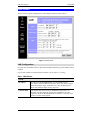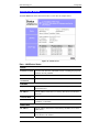
1
Broadband Router
Shared Broadband Internet Access
CNIG904S
4-port Swtiching Hub
User’s Guide
TABLE OF CONTENTS
CHAPTER 1 INTRODUCTION ..............................................................................................1
Broadband Router Features .............................................................................................1
Package Contents...............................................................................................................3
Physical Details ..................................................................................................................4
CHAPTER 2 INSTALLATION ...............................................................................................6
Requirements......................................................................................................................6
Installation Procedure .......................................................................................................6
CHAPTER 3 CONFIGURATION ...........................................................................................8
Overview.............................................................................................................................8
Configuration Program.....................................................................................................9
LAN Screen ......................................................................................................................11
WAN Configuration ........................................................................................................13
WAN Status......................................................................................................................16
LAN/Device Status...........................................................................................................19
CHAPTER 4 PC CONFIGURATION...................................................................................21
Overview...........................................................................................................................21
TCP/IP Settings................................................................................................................21
Internet Access Configuration ........................................................................................24
Macintosh Configuration ................................................................................................25
CHAPTER 5 DHCP ................................................................................................................26
Overview...........................................................................................................................26
What DHCP Does ............................................................................................................26
Using the Broadband Router's DHCP Server ...............................................................26
Using another DHCP Server...........................................................................................26
To Configure your PCs to use DHCP.............................................................................27
CHAPTER 6 ROUTING.........................................................................................................28
Overview...........................................................................................................................28
Broadband Router Configuration ..................................................................................28
Router Configuration ......................................................................................................30
Routing Example..............................................................................................................30
CHAPTER 7 DEVICE OPTIONS..........................................................................................32
Overview...........................................................................................................................32
Password...........................................................................................................................32
NAT (Network Address Translation).............................................................................33
TFTP .................................................................................................................................33
Remote Management .......................................................................................................33
CHAPTER 8 ADVANCED INTERNET ...............................................................................34
Overview...........................................................................................................................34
Advanced Internet Screen...............................................................................................34
Special Internet Applications..........................................................................................35
Virtual Servers .................................................................................................................37
DMZ..................................................................................................................................41
CHAPTER 9 ACCESS CONTROL .......................................................................................43
Overview...........................................................................................................................43
Security Groups ...............................................................................................................44
PCs ....................................................................................................................................46
Filters ................................................................................................................................47
i
APPENDIX A TROUBLESHOOTING.................................................................................49
Overview...........................................................................................................................49
General Problems.............................................................................................................49
Internet Access .................................................................................................................50
APPENDIX B SPECIFICATIONS ........................................................................................51
Broadband Router ...........................................................................................................51
P/N: 9560DN0001
Copyright 2001. All Rights Reserved.
Document Version: 1.0
All trademarks and trade names are the properties of their respective owners.
ii
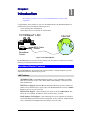
Chapter 1
Introduction
This Chapter provides an overview of the Broadband Router's features and
capabilities.
1
Congratulations on the purchase of your new Broadband Router. The Broadband Router is a
multi-function device providing the following services:
4 Port Switching hub (10/100BaseT).
Shared Internet access via an DSL or Cable modem.
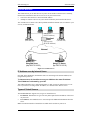
10/100BaseT LAN
Internet
ADSL/Cable
Modem
Broadband
Router
Figure 1: Broadband Router
The Broadband Router can also be used to connect your local LAN to a remote LAN or WAN,
instead of providing shared Internet Access.
Broadband Router Features
The Broadband Router incorporates many advanced features, carefully designed to provide
sophisticated functions while being easy to use.
LAN Features
10/100BaseT Hub. The Broadband Router includes a 4-port 10/100BaseT switching
Hub, allow connection of up to 4 PCs. Both 10BaseT and 100BaseT connections can be
used simultaneously.
DHCP Server Support. Dynamic Host Configuration Protocol provides a dynamic IP
address to PCs and other devices upon request. The Broadband Router can act as a DHCP
Server for devices on your local LAN.
DHCP Client Support. On the WAN port, the router can act as a DHCP Client. This
allows the use of dynamic IP Addresses on the “External LAN” or WAN.
Multi Segment LAN Support. LANs containing one or more segments are supported,
via the Broadband Router's built-in static routing table. If NAT (Network Address Translation) is disabled, the Broadband Router will function as a static router.
1
CNet Technology Inc
Broadband Router User Guide
Internet Access Features
•
Shared Internet Access. All users on the LAN can access the Internet through the
Broadband Router, using only a single external IP Address. The local (invalid) IP Addresses are hidden from external sources. This process is called NAT (Network Address
Translation).
•
ADSL & Cable Modem Support. The Broadband Router has a 10BaseT Ethernet port
•
PPPoE Support. Connect to your ISP using PPPoE (PPP over Ethernet), if your ISP
•
Fixed or Dynamic IP Address. On the WAN connection, the Broadband Router
supports both Dynamic IP Address (IP Address is allocated on connection) and Fixed IP
Address.
for connecting an ADSL or Cable Modem. All popular ADSL and Cable Modems are supported.
uses this method.
Configuration & Management
•
Easy Setup. Use your WEB browser from anywhere on the LAN for configuration.
•
Remote Management. The Broadband Router can be managed from a workstation
anywhere on the LAN, using a WEB browser.
Advanced Internet Functions
•
•
Virtual Servers. This feature allows Internet users to access Internet servers on your
LAN. The required setup is quick and easy.
User-Defined Virtual Servers. Internet users can access non-standard Internet Servers
on your LAN by using this feature.
•
Special Internet Applications. Internet applications such as Internet Videoconferenc-
•
DMZ. One (1) PC on your local LAN can be configured to allow unrestricted 2-way
ing, Telephony, Games Servers, and other special-purpose Servers are supported.
communication with Servers or individual users on the Internet.
Security Features
•
Configuration Data. Optional password protection is provided to prevent unauthorized
•
Access Control Features. The LAN Administrator can limit Internet access by individ-
•
Firewall Protection. All incoming data packets are monitored and all incoming server
users from modifying the configuration.
ual PCs.
requests are filtered, thus protecting your network from malicious attacks from external
sources. (This protection is lost if NAT is disabled.)
2
CNet Technology Inc
Introduction
NAT Firewall Protection
The firewall protection provided by the Broadband Router is an intrinsic side
effect of NAT (Network Address Translation). All users on the LAN share a
single external IP address. From the external viewpoint, there is no network, only
a single device.
For internal users, the Broadband Router acts as a “transparent proxy server”,
translating the multiple internal IP addresses into a single external IP address.
For external requests, any attempt to connect to local resources are blocked. The
Broadband Router will not “reverse translate” from a global IP address to a local
IP address.
This type of “natural” firewall provides an impregnable barrier against malicious
attacks.
Package Contents
The following items should be included:
•
The Broadband Router Unit
•
Power Adapter
•
Quick Installation Guide
•
CD-ROM containing the on-line manual.
If any of the above items are damaged or missing, please contact your dealer as soon as possible.
3
CNet Technology Inc
Physical Details
Please take a few minutes to familiarize yourself with the Broadband Router.
Top - Mounted LEDs
There are 2 LEDs on the top of the unit. The "DATA STATUS LAN" LED has 2 colors Green and Orange. Operation of these LEDs is as follows:
DATA STATUS LAN
(Green/Orange)
On (Green) - Normal start up/power on sequence, or idle.
The Data/Status LED will flash under the following conditions:
•
Flashing (Green) – The Data/Status LED will flash when
data is transmitted or received through the LAN ports.
•
Flashing (Orange, Green, Orange,…) – Hardware error.
Contact your dealer for technical support.
On - Normal start up (power ON) sequence or idle.
DATA WAN
(Green)
Flashing – The Data LED will flash when data is transmitted or
received through the WAN port.
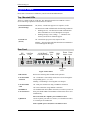
Rear Panel
DIP
switches
Link/
10/100 BaseT Uplink
LAN Connectors port
LAN Port
LEDS
1 2 3
LAN
4
WAN
port
Reset Power
button Input
WAN
RESET
Act
100
1
2
3
4
Uplink
Figure 2: Rear Panel
WAN port
LED
DIP switches
Refer to the following table for DIP switch operation.
LAN Port LEDs
- Link/Act
On - The Router is successfully connected to a device through the
corresponding port (1, 2, 3, or 4).
Flashing - Transmitting or receiving data over that port.
LAN Port LEDs
- 100
On - LAN port connection is using a 100BaseT connection.
10/100BaseT
LAN Connectors
Use standard LAN cables (RJ45 connectors) to connect your PCs ot
these ports. Both 10BaseT and 100BaseT connections can be used
simultaneously.
Off - Port is unused or using 10BaseT connection.
If Port 4 is used, the "Uplink" port can NOT be used..
Uplink Port
Use the "Uplink" port ONLY to connect (via a normal LAN cable)
to a normal port on another hub.
If the "Uplink" port is used, Port 4 can NOT be used.
4
CNet Technology Inc
Introduction
WAN port
(10BaseT)
Connect the ADSL or Cable Modem here. If your modem came
with a cable, use the supplied cable. Otherwise, use a standard LAN
cable.
WAN Port LED
Flashing - data is being transmitted or received via the WAN port.
OFF - no data is being transferred.
Reset Button
When pressed and released, the Broadband Router will reboot
(restart).
Power port (12V)
Connect the supplied power adapter here.
DIP Switches
DIP Switch Setting
Description
1=off
2=off
Normal Operation
1=off
2=on
DHCP Server function disabled.
1=on
2=off
Used to restore Default IP Address
and clear Password (See below)
1=on
2=on
Normal Operation.
Restore Default IP Address and Clear Password
If the Broadband Router's IP Address or password is lost, the following procedure can be used
to recover from this situation.
1. Turn the power to the Broadband Router OFF.
2. Set DIP switch 1 ON.
3. Turn the power to the Broadband Router ON.
4. Operate DIP switch 1 in the following sequence (you have 15 seconds to complete the
sequence):
5.
•
OFF
•
ON
• OFF
The Broadband Router will now reset, and the Yellow Status LED flash. The following
changes will have been made. (Other configuration data is unchanged.)
•
6.
IP Address set to its default value of 192.168.0.1
•
Network Mask set to 255.255.255.0
•
DHCP Server is enabled, and will allocate IP Addresses in the range 192.168.0.2 to
192.168.0.51.
• The password cleared (no password).
You can now connect to the Broadband Router and make any configuration changes
required.
5
2
Chapter 2
Installation
This Chapter covers the physical installation of the Broadband Router.
Requirements
•
Ethernet LAN (10/100BaseT) and the TCP/IP protocol.
•
For Internet Access, a DSL or Cable modem, and an Internet Access account with an ISP.
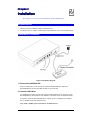
Installation Procedure
Figure 3 Installation Diagram
1. Choose an Installation Site
Select a suitable place on the network to install the Broadband Router. Ensure the
Broadband Router and the Cable/DSL modem are powered OFF.
2. Connect LAN Cables
Use standard LAN cables to connect PCs to the Switching Hub ports (LAN ports) on the
Broadband Router. Both 10BaseT and 100BaseT connections can be used simultaneously.
If required, connect the Broadband Router's "Uplink" port to a standard port on another
hub. A standard LAN cable should be used.
Note: If the "Uplink" port is used, Port 4 can NOT be used.
6
CNet Technology Inc
Installation
3. Connect ADSL or Cable Modem
Connect the ADSL or Cable modem to the WAN port on the Broadband Router. Use the
cable supplied with your modem. If no cable was supplied, use a standard LAN cable.
4. Power Up
Connect the supplied power adapter and power up.
Use only the power adapter provided. Using a different one may cause hardware damage
5. Check the LEDs
When the Broadband Router is powered On, the DATA STATUS LAN LED should flash,
then turn on. If it stays flashing (in Green and Orange), there is a hardware error.
For more information, refer to Top - Mounted LEDs in Chapter 1.
7
3
Chapter 3
Configuration
This Chapter provides details of the configuration process.
Overview
This chapter describes the procedure for:
•
LAN setup
•
WAN port configuration for Internet Access
PCs on your local LAN may also require configuration. For details, see Chapter 4 - PC Configuration.
Other configuration may also be required, depending on which features and functions of the
Broadband Router you wish to use. Use the table below to locate detailed instructions for the
required functions.
To Do this:
Refer to:
Configure PCs on your LAN.
Chapter 4:
PC Configuration
Learn more about using DHCP on the internal LAN
Chapter 5:
DHCP
Configure the Broadband Router and routers for a LAN which
has 1 or more routers.
Chapter 6:
Routing
Set a password for the Broadband Router, or disable NAT
(Network Address Translation).
Chapter 7:
Options
Use any of the following features:
Chapter 8:
Advanced Internet
Features
•
Special Internet Applications
•
Virtual Servers
•
DMZ
Limit Internet Access by individual PCs
Chapter 9:
Access Control
Where use of a certain feature requires that
PCs or other LAN devices be configured, this
is also explained in the relevant chapter.
8
CNet Technology Inc
Configuration
Configuration Program
The Broadband Router contains a HTTP server. This enables you to connect to it, and configure it, using your Web Browser.
Most Browsers should work, provided they support HTML tables and forms.
Preparation
Before attempting to configure the Broadband Router, please ensure that:
•
Your PC can establish a physical connection to the Broadband Router. The PC and the
Broadband Router must be directly connected (using one of the Switching Hub ports on the
Broadband Router) or on the same LAN segment.
•
The Broadband Router must be installed and powered ON.
•
If the Broadband Router's default IP Address (192.168.0.1) is already used by another
device, the other device must be turned OFF until the Broadband Router is allocated a new
IP Address during configuration.
Connecting to the Broadband Router
To establish a connection from your PC to the device:
1. After installing the Broadband Router in your LAN, start your PC. If your PC is already
running, restart it.
2. Start your WEB browser.
3. In the Address box, enter "HTTP://" and the IP Address of the Broadband Router, as in the
following example, which uses the Broadband Router’s default IP Address:
HTTP://192.168.0.1
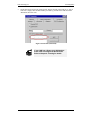
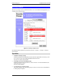
4.
If you have assigned a password to the Broadband Router you will be prompted for the
password, as shown below. (If no password has been set, this dialog will not appear.)
•
Leave the "User Name" blank.
•
Enter the password for this device, if one has been set.
Figure 4: Password Dialog
5.
You should then see the LAN screen.
See the following section for the available options and configuration screens.
9
CNet Technology Inc
Broadband Router User Guide
If you can't connect
If the Broadband Router does not respond, check the following:
•
The Broadband Router is properly installed, LAN connection is OK, and it is
powered ON.
•
Ensure that your PC and the Broadband Router are on the same network
segment. (If you don't have a router, this must be the case.)
•
If your PC is using a fixed IP Address, its IP Address must be within the
range 192.168.0.2 to 192.168.0.254 to be compatible with the Broadband
Router's default IP Address of 192.168.0.1. Also, the Network Mask must be
set to 255.255.255.0. See Chapter 4 – PC Configuration for details on
checking your PC’s TCP/IP settings.
Navigation & Data Input
•
Use the menu bar on the left of the screen, and the "Back" button on your Browser, for
navigation.
•
Changing to another screen without clicking "Save" does NOT save any changes you may
have made. You must “Save” before changing screens or your data will be ignored.
On each screen, clicking this icon will display
help for that screen.
10
CNet Technology Inc
Configuration
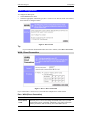
LAN Screen
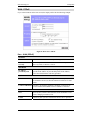
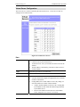
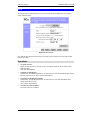
The LAN screen, like the example below, will be displayed when you first connect.
Figure 5: LAN Screen
LAN Configuration.
For most users, the default values for these fields should be satisfactory, and no changes will be
required.
If your LAN contains an existing Router or Routers, refer to Chapter 6 - Routing.
Data – LAN Screen
TCP/IP
IP Address
IP address for the Broadband Router. Use the default value of
192.168.0.1 unless the address is already in use or your LAN is using a
different IP address range. In the latter case, enter an unused IP Address from within the range used by your LAN.
Network Mask
The default value 255.255.255.0 is standard for small (class "C")
networks. For other networks, use the Network Mask for the LAN
segment to which the Broadband Router is attached. i.e. the same value
as the PCs on that LAN segment.
11
CNet Technology Inc
Broadband Router User Guide
DHCP Server
Operation
If Enabled, the Broadband Router will allocate IP Addresses to PCs on
your LAN. The default and recommended value is Enabled.
If you are already using a DHCP Server, this setting must be
DISABLED, and the existing DHCP server must be re-configured. See
Chapter 5 for further details.
Start IP Address
Finish IP Address
The IP Start Address and IP Finish Address fields set the values used
by the DHCP server.
This range also determines the number of DHCP clients supported.
(Maximum 253.)
DNS (Domain Name Server)
DNS (Domain
Name Server)
IP Addresses
You do NOT need to enter DNS addresses UNLESS you are using a
Fixed IP Address on the WAN port. (Your ISP has allocated you a
fixed IP Address.) In this case, your ISP should recommend a DNS.
You need to enter that address or addresses here.
If using a Dynamic IP Address (DHCP Client), on the WAN port, the
DNS entries are optional.
Multiple DNS entries should be entered in the order you want them
accessed. (The first available DNS will be used.)
Routing Table
Routing Table
If your LAN contains an existing Router or Routers, refer to Chapter 6
- Routing.
12
CNet Technology Inc
Configuration
WAN Configuration
To configure the WAN port:
•
Select WAN from the menu.
•
Select the appropriate connection type (Direct Connection or PPPoE) on the screen below,
then Click the “Configure” button.
Figure 6: WAN Screen
Tip:
If your connection documentation does not refer to PPPoE, select Direct Connection.
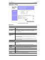
WAN - Direct Connection
Figure 7: WAN - Direct Connection
If you selected Direct Connection, a screen like the example above will be shown.
Data - WAN (Direct Connection)
Device ID
Device (Host)
Name
Normally, there is no need to change the default name, but if your ISP
requests that you use a particular “Hostname”, enter it here. This name
will be provided to, and recorded by, the remote DHCP Server.
13
CNet Technology Inc
Hardware
(MAC)
Address
Broadband Router User Guide
Also called Network Adapter Address or Physical Address. Provide this
value to your ISP if requested. If you did not provide this value when
first connected, there is no need to provide it now.
IP Address
Dynamic
IP Address
(DHCP Client)
Leave this enabled if you want your ISP to allocate an IP Address to the
Broadband Router upon connection.
Fixed
IP Address
Select this if using a fixed IP Address. If this option is selected, the
following data must be entered.
•
IP Address.
If connecting to an ISP, this is the address allocated by the ISP. If
connecting to another LAN, this must be a valid address on the external LAN.
•
Network Mask
This must be compatible with the IP Address above
•
Gateway IP Address
The address of the router or gateway, either on the external LAN, or
supplied by your ISP.
DNS IP Address
At least 1 DNS IP Address is required, and should be provided by your
ISP. DNS settings are on the LAN screen.
Buttons
Retrieve
Defaults
Get the default Device Name and clear the other items. No changes are
made to the configuration until you click the Save button.
Save
Save any data you have entered on this screen. Remember to save before
changing to another screen.
Cancel
Cancel any data you have entered since the last "Save" operation.
Note:
If using Dynamic IP Address, the IP Address, Network Mask, and Gateway fields may display the values obtained dynamically.
14
CNet Technology Inc
Configuration
WAN - PPPoE
If you selected PPPoE on the WAN screen, the display will be like the following example.
Figure 8: WAN Port - PPPoE
Data – WAN (PPPoE)
Account
Account/User Name
The name of the Internet account provided by your ISP.
Password
& Verify
Enter the password for the above account. Re-enter the password in
the Verify field, to ensure it is correct.
IP Address
IP Address
provided by ISP
Normally, this is Dynamic; use this setting if your ISP did not
provide an IP Address. If your ISP did provide an IP Address,
select Fixed and enter the value they provided.
Options
Idle Time-out
If an connection is inactive for longer than this time period, it will
be terminated. If zero (0), then the connection will never be terminated.
Connect on Demand
Normally, this should be Enabled. If disabled, you must use the
Connect button on the Status screen to establish a connection.
Buttons
Save
Save any data you have entered on this screen. Remember to save
before changing to another screen.
Cancel
Cancel any data you have entered since the last "Save" operation.
15
CNet Technology Inc
Broadband Router User Guide
WAN Status
Clicking WAN Status on the menu bar will take you to the WAN Status screen. The screen
shown will depend on whether you are using a Direct Connection or PPPoE.
WAN Status – Direct Connection
Figure 9: WAN Status – Direct Connection
Data
WAN Status
Physical Address
The "Hardware" address of this device, as seen by other devices on the
WAN.
IP Address
The IP Address of this device, as seen by devices on the WAN.
(This device has 2 IP Addresses; one for the local LAN, and another
for the WAN port.)
Network Mask
The Network Mask for the above IP Address.
Default Gateway
IP address of the Router/Gateway on the WAN port.
DHCP Client
Displays "Enabled" or "Disabled", indicating whether this device is
acting as a DHCP client on the external LAN or WAN.
Buttons
Reconnect
Use this button if the connection seems to have been lost, and no data is
being transferred. (This button has no effect unless acting as a DHCP
Client.)
Refresh
Update the data on screen.
16
CNet Technology Inc
Configuration
WAN Status – PPPoE
Figure 10: WAN Status – PPPoE
Status Data
WAN Status
Physical Address
The "Hardware" address of this device, as seen by other devices on the
WAN.
IP Address
The IP Address of this device, as seen by devices on the WAN.
(This device has 2 IP Addresses; one for the local LAN, and another
for the WAN port.)
Network Mask
The Network Mask (Subnet Mask) for the IP Address above.
PPPoE Link
Status
This indicates whether or not the connection is currently established.
If the connection does not exist, the Connect button can be used to
establish a connection.
If the connection currently exists, the Disconnect button can be used to
break the connection.
Connection Log
Log Data
The Connection Log shows status messages relating to the existing
connection.
The most common messages are listed in the following table.
Buttons
Connect
If not connected, establish a connection to your ISP
Disconnect
If connected to your ISP, hang up the connection.
Clear Log
Delete all data currently in the Log. This will make it easier to read new
messages.
Refresh
Contact this device and update the Log data.
17
CNet Technology Inc
Broadband Router User Guide
Connection Log Messages
Message
Description
Connect on
Demand
Connection attempt has been triggered by the "Connect on Demand" setting.
Manual connection
Connection attempt started by the "Connect" button.
Reset physical
connection
Preparing line for connection attempt.
Connecting to remote
server
Attempting to connect to the ISP's server.
Remote Server
located
ISP's Server has responded to connection attempt.
Start PPP
Attempting to login to ISP's Server and establish a PPP connection.
PPP up successfully
Able to login to ISP's Server and establish a PPP connection.
Idle time-out reached
The connection has been idle for the time period specified in the
"Idle Time-out" field. The connection will now be terminated.
Disconnecting
The current connection is being terminated, due to either the "Idle
Time-out" above, or "Disconnect" button being clicked.
Error: Remote Server
not found
ISP's Server did not respond. This could be a Server problem, or a
problem with the link to the Server.
Error: PPP Connection failed
Unable to establish a PPP connection with the ISP's Server. This
could be a login problem (name or password) or a Server problem.
Error: Connection to
Server lost
The existing connection has been lost. This could be caused by a
power failure, a link failure, or Server failure.
Error: Invalid or
unknown packet type
The data received from the ISP's Server could not be processed.
This could be caused by data corruption (from a bad link), or the
Server using a protocol which is not supported by this device.
18
CNet Technology Inc
Configuration
LAN/Device Status
The LAN Status link on the menu will result in a screen like the example below.
Figure 11: Status Screen
Data – LAN/Device Status
Device
Firmware Version
Version of the firmware (embedded software, including this program)
which is currently installed.
Hardware ID
The hardware ID of this device, used by the manufacturer.
Network Address
Translation
This will display "Enabled" (NAT is On) or "Disabled" (NAT is Off)
LAN Port
Physical Address
The "Hardware" address of this device, as seen by other devices on
the Internal LAN.
IP Address
The IP Address of this device, as seen by other devices on the Internal LAN.
Network Mask
The Network Mask (Subnet Mask) for the IP Address above.
DHCP Server
This shows the status of the DHCP Server function. The value will be
"Enabled" or "Disabled".
DHCP Table
IP Address
The IP Address which has been allocated by the DHCP server to the
other device.
Physical Address
The Physical Address (Hardware Address) of the device which has
been allocated a IP Address.
19
CNet Technology Inc
Status
Broadband Router User Guide
Possible Status values are "Leased" (the IP Address is allocated to the
device shown) or "Reserved" (the IP Address is not available).
Note:
The DHCP table will be empty unless the DHCP Server function is being used. If not
empty, this table lists the devices on the LAN which have been allocated IP Addresses by
the DHCP server function.
20
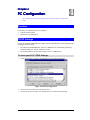
Chapter 4
PC Configura
Configuration
4
This Chapter details the PC Configuration required on the local ("Internal")
LAN.
Overview
For each PC, the following may to be configured:
•
TCP/IP network settings
•
Internet Access configuration
TCP/IP Settings
If using the default Broadband Router settings, and the default Windows 95/98 TCP/IP settings,
no changes need to be made.
•
By default, the Broadband Router will act as a DHCP Server, automatically providing a
suitable IP Address to each PC when the PC boots.
•
The default Windows 95/98 TCP/IP setting is to act as a DHCP client.
To check your PC's TCP/IP Settings:
1.
Select Control Panel - Network. You should see a screen like the following:
Figure 12: Network Configuration
2.
3.
Select the TCP/IP protocol for your network card.
Click on the Properties button. You should then see a screen like the following.
21
CNet Technology Inc
Broadband Router User Guide
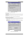
Figure 13: IP Address (Win 95)
Ensure your TCP/IP settings are correct, as follows:
Using DHCP
To use DHCP, select the radio button Obtain an IP Address automatically. This is the default
Windows settings.
Restart your PC to ensure it obtains an IP Address from the Broadband Router.
Using “Specify an IP Address”
•
If your PC is already configured, do NOT change the settings on the IP Address tab shown
in Figure 13 above.
•
On the Gateway tab, enter the Broadband Router's IP address in the New Gateway field
and click Add. Your LAN administrator can advise you of the IP Address they assigned to
the Broadband Router.
Figure 14: Gateway Tab (Win 95/98)
22
CNet Technology Inc
•
PC Configuration
On the DNS Configuration tab, ensure Enable DNS is selected. If the DNS Server Search
Order list is empty, enter the DNS address provided by your ISP in the fields beside the
Add button, then click Add.
Figure 15: DNS Tab (Win 95/98)
If your LAN has a Router, the LAN Administrator must re-configure the Router itself.
Refer to Chapter 6 - Routing for details.
23
CNet Technology Inc
Broadband Router User Guide
Internet Access Configuration
If you are using the Broadband Router for Internet access:
•
Ensure that the DSL modem, Cable modem, or other permanent connection is functional.
•
Use the following procedure to configure your Browser to access the Internet via the LAN,
rather than by a Dial-up connection.
1.
2.
3.
Select Start Menu - Settings - Control Panel - Internet Options.
Select the Connection tab, and click the Setup button.
Select "I want to set up my Internet connection manually, or I want to connect through a
local area network (LAN)" and click "Next".
Select "I connect through a local area network (LAN)" and click "Next".
Ensure all of the boxes on the following Local area network Internet Configuration screen
are unchecked.
Check the "No" option when prompted “Do you want to set up an Internet mail account
now?”.
Click "Finish" to close the Internet Connection Wizard.
Then simply use your Browser, FTP client, or other Internet client to connect to the desired
Internet site.
4.
5.
6.
7.
8.
Accessing AOL
To access AOL (America On Line) through the Broadband Router, the AOL for Windows
software must be configured to use TCP/IP network access, rather than a dial-up connection.
The configuration process is as follows:
•
Start the AOL for Windows communication software. Ensure that it is Version 2.5, 3.0 or
later. This procedure will not work with earlier versions.
•
Click the Setup button.
•
Select Create Location, and change the location name from "New Locality" to "Broadband
Router".
•
Click Edit Location. Select TCP/IP for the Network field. (Leave the Phone Number
blank.)
•
Click Save, then OK.
Configuration is now complete.
•
Before clicking "Sign On", always ensure that you are using the "Broadband Router"
location.
24
CNet Technology Inc
PC Configuration
Macintosh Configuration
You can access the Internet via the Broadband Router. The procedure is as follows.
1.
2.
3.
4.
Open the TCP/IP Control Panel.
Select Ethernet from the Connect via pop-up menu.
Select Using DHCP Server from the Configure pop-up menu. The DHCP Client ID field
can be left blank.
Close the TCP/IP panel, saving your settings.
Note:
If using manually assigned IP addresses instead of DHCP, the only change required is to
set the Router Address field to the Broadband Router's IP Address.
25
Chapter 5
DHCP
5
This Chapter covers the use of DHCP, using either an existing DHCP Server
or the Broadband Router's DHCP Server function.
Overview
If your LAN does not use DHCP, and you do not wish to use DHCP, you can ignore this
chapter.
What DHCP Does
A DHCP (Dynamic Host Configuration Protocol) server allocates a valid IP address to a
DHCP client (PC or device) upon request.
•
The client request is made when the client device boots.
•
The DHCP Server provides the Gateway and DNS addresses to the client, as well as
allocating an IP Address.
•
Windows 95/98/ME include all the software required to act as a DHCP client. This is the
default Windows setting for TCP/IP.
•
The Broadband Router can act as a DHCP server.
Using the Broadband Router's DHCP Server
This is the default setting. The DHCP Server settings are on the LAN screen. On this screen,
you can:
•
Enable or Disable the Broadband Router's DHCP Server function.
•
Set the range of IP Addresses allocated to PCs by the DHCP Server function.
You can assign Fixed IP Addresses to some devices
while using DHCP, provided that the Fixed IP Addresses
are NOT within the range used by the DHCP Server.
Using another DHCP Server
You can only use one (1) DHCP Server. If you wish to use another DHCP Server, rather than
the Broadband Router’s, the following procedure is required.
1. Disable the DHCP Server feature in the Broadband Router. This setting is on the LAN
screen.
2. Configure the DHCP Server to provide the Broadband Router’s IP Address as the Default
Gateway.
26
CNet Technology Inc
DHCP
To Configure your PCs to use DHCP
This is the default setting for TCP/IP under Windows 95/98/ME.
In Windows, the DHCP Client setting is called "Obtain an IP Address Automatically".
See Chapter 4 – PC Configuration for the procedure to check these settings.
27
6
Chapter 6
Routing
This Chapter explains the Routing features of the Broadband Router.
Overview
While the Broadband Router includes a standard (static) routing table, this feature can be
completely ignored if you do not have a router in your LAN.
If you DO have a router, it is necessary to configure BOTH the Router and the Routing table in
the Broadband Router correctly, as described in the following sections.
See Routing Example later in this Chapter
for an example of configuring both the
Broadband Router and the Router.
Broadband Router Configuration
The routing table is accessed by the Routing link on the Home screen. An example screen is
shown below.
Figure 16: Routing Screen
Using this Screen
•
Any existing entries are listed.
•
To view and edit the details of an existing entry, select it, and click "Get Data". After
making any changes, click the "Update" button to save your changes.
•
To add a new entry, click "Clear Form", enter your data, then click the "Add" button.
28
CNet Technology Inc
Routing
Routing Table Data
An entry in the routing table is required for each LAN segment on your Network, other than the
segment to which this device is attached. The data in the Routing Table is as follows.
Destination
IP Address
The network address of the remote LAN segment.
For standard class "C" LANs, the network address is the first 3 fields of
this Destination IP Address. The 4th (last) field can be left at 0.
Network Mask
The Network Mask used on the remote LAN segment. For class "C"
networks, the standard Network Mask is 255.255.255.0
Gateway
IP Address
The IP Address of the Router on the LAN segment to which this device is
attached. (NOT the router on the remote LAN segment.)
Interface
Select the appropriate interface - LAN (Internal LAN) or WAN (External
LAN or WAN) from the drop-down list.
Metric
The number of routers which must be traversed to reach the remote LAN
segment. The default value is 1.
29
CNet Technology Inc
Broadband Router User Guide
Router Configuration
It is essential that all IP packets for devices not on the local LAN be passed to the Broadband
Router, so that they can be forwarded to the external LAN, WAN, or Internet. To achieve this,
the local LAN must be configured to use the Broadband Router as the Default Route or Default
Gateway.
Local Router
The local router is the Router installed on the same LAN segment as the Broadband Router.
This router requires that the Default Route is the Broadband Router itself. Typically, routers
have a special entry for the Default Route. It should be configured as follows.
Destination IP Address
Normally 0.0.0.0, but check your router
documentation.
Network Mask
Normally 0.0.0.0, but check your router
documentation.
Gateway IP Address
The IP Address of the Broadband Router.
Metric
1
Other Routers on the Local LAN
Other routers on the local LAN must use the Broadband Router's Local Router as the Default
Route. The entries will be the same as the Broadband Router's local router, with the exception
of the Gateway IP Address.
•
For a router with a direct connection to the Broadband Router's local Router, the Gateway
IP Address is the address of the Broadband Router's local router.
•
For routers which must forward packets to another router before reaching the Broadband
Router's local router, the Gateway IP Address is the address of the intermediate router.
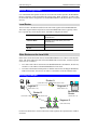
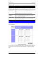
Routing Example
Router A
(192.168.1.80)
(192.168.0.100)
Segment 1
Segment 0
(192.168.1.xx)
(192.168.0.xx)
Router B
(192.168.1.90)
(192.168.2.70)
Broadband
Router
(192.168.0.1)
Segment 2
(192.168.2.xx)
Figure 17: Routing Example
For the LAN shown above, with 2 routers and 3 LAN segments, the required entries would be
as follows.
30
CNet Technology Inc
Routing
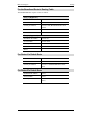
For the Broadband Router's Routing Table
The Broadband Router requires 2 entries as follows.
Entry 1 (Segment 1)
Destination IP Address
192.168.1.0
Network Mask
255.255.255.0 (Standard Class C)
Gateway IP Address
192.168.0.100 (Broadband Router's local
Router)
Interface
LAN
Metric
1
Entry 2 (Segment 2)
Destination IP Address
192.168.2.0
Network Mask
255.255.255.0
Gateway IP Address
192.168.0.100
Interface
LAN
Metric
2
For Router A's Default Route
Destination IP Address
0.0.0.0
Network Mask
0.0.0.0
Gateway IP Address
192.168.0.1 (Broadband Router's IP Address)
For Router B's Default Route
Destination IP Address
0.0.0.0
Network Mask
0.0.0.0
Gateway IP Address
192.168.1.80 (Broadband Router's local
router)
31
Chapter 7
Device Options
7
This Chapter details the options available on the Broadband Router's "Options" screen.
Overview
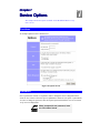
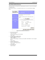
An example Options screen is shown below.
Figure 18: Options Screen
Password
Once a password is entered, it is required in order to change the device configuration. Passwords are case sensitive and can be up to 8 alphanumeric characters (no spaces or punctuation).
To create or change the password, enter the required password in both the New Password and
Verify Password input fields.
When prompted for the password, leave
the "User Name" blank.
32
CNet Technology Inc
Options
NAT (Network Address Translation)
NAT allows PCs on your LAN to share a single external (Internet) IP Address. This IP Address
is supplied by your ISP. Use the following to determine whether or nor you need NAT.
•
For Internet access, NAT must be left On unless all PCs on your LAN have valid external
IP Addresses.
•
If this device is not being used to provide shared Internet access, NAT is not normally
required. With NAT disabled, the Broadband Router will act as a static router.
•
If NAT is disabled, the Firewall protection provided by the Broadband Router is lost, and
the Advanced Internet features (Virtual Servers, Special Applications, and DMZ) are no
longer available.
TFTP
TFTP (Trivial FTP) can be used to upgrade the firmware in the Broadband Router. However,
this is not normally required; there is a Windows utility available for this purpose.
Remote Management
This feature allows you to manage the Broadband Router via the Internet.
Enable Remote Management
Enable to allow management via the Internet. If Disabled, this
device will ignore management connection attempts from the
WAN port.
Port Number
Enter a port number between 1024 and 65535 (8080 is recommended). This port number must be specified when you connect
(see below).
Note: The default port number for HTTP (Web) connections is
port 80, but using port 80 here will prevent the use of a Web
"Virtual Server" on your LAN. (See Advanced Internet - Virtual
Servers)
Current WAN Port
IP Address
You must use this IP Address to connect (see below).
This IP Address is allocated by your ISP. But if using a Dynamic IP Address, this value can change each time you connect
to your ISP. So it is better if your ISP allocates you a Fixed IP
Address.
To connect from a remote PC via the Internet
1.
2.
Ensure your Internet connection is established, and start your Web Browser.
In the "Address" bar, enter "HTTP://" followed by the WAN IP Address of the Broadband
Router. If the port number is not 80, the port number is also required. (After the IP Address, enter ":" followed by the port number.)
e.g.
HTTP://123.123.123.123:8080
This example assumes the WAN IP Address is 123.123.123.123, and the port number is
8080.
33
Chapter 8
Advanced Inter
Internet
8
This Chapter explains how to use the "Advanced Internet" features.
Overview
For situations where the Broadband Router is being used to provide shared Internet access, the
following advanced features are provided.
•
Special Internet Applications
•
Virtual Servers
•
DMZ
This chapter contains details of the configuration and use of each of these features.
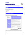
Advanced Internet Screen
This screen provides access to the advanced Internet features, and provides a convenient
overview and control center. An example screen is shown below.
Figure 19: Advanced Internet Screen
On this screen, you can enable any required feature. By default, all features are disabled.
34
CNet Technology Inc
Advanced Internet
Special Internet Applications
This feature is only required if you wish to use Internet applications which require 2-way
communication, multiple connections, or combined TCP/UDP connections.
Examples of such applications are Internet Videoconferencing, Telephony, Games Servers, and
other special-purpose Servers.
Generally, you will become aware of the need for this feature when an Internet application is
unable to function correctly.
At any time, only one (1) PC can use
each Special Application.
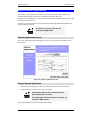
Special Applications Screen
This screen can be reached by selecting Special Internet Applications. An example screen is
shown below.
Figure 20: Special Applications Screen
Using a Special Application
•
Ensure that Special Applications has been enabled on the Advanced Internet screen.
•
Configure the Special Applications screen as required.
Configuration data must be obtained from the
Service/Application provider.
If an application still cannot function correctly, try
using the "DMZ" feature.
Some Special Applications have been defined not enabled.
35
CNet Technology Inc
•
To Enable a defined Application
- Select it from the drop-down list
- Click "Get Data"
- Check the Enable checkbox
- Click "Update"
•
To Disable a defined Application
- As above, but uncheck the Enable checkbox.
•
To Delete a defined Application
- Select it from the drop-down list,
- Click "Delete"
•
To Modify (Edit) a defined Application
- Select it from the drop-down list,
- Click "Get Data"
- Make any desired changes
- Click "Update"
•
To Create a new Application
- Click "Clear Form"
- Enter the required data, as described below
- Click "Add"
•
To List all Applications
- Click "List All"
Broadband Router User Guide
Configuration Data (from Service Provider)
This data must be obtained from the service provider.
Name
Enter a descriptive name to identify this application entry.
Enable
Use this to Enable or Disable support for this application, as required.
Outgoing
Protocol
The protocol (TCP or UDP) used when you connect to the special application service.
Port Range:
Start
The beginning of the range of port numbers used by the application server,
for data you send to it. If the application uses a single port number, enter it in
both the "Start" and "Finish" fields.
Port Range:
Finish
The end of the range of port numbers used by the application server, for data
you send.
Incoming
Protocol
The protocol (TCP or UDP) used when the application or service sends data
to you.
Port Range:
Start
The start of the range of port numbers used by the application server when
data is sent to you. If using only one port number, enter it in both the "Start"
and "Finish" fields.
Port Range:
Finish
The end of the range of port numbers used by the application server, when
data is sent to you.
36
CNet Technology Inc
Advanced Internet
Virtual Servers
This feature allows you to make Servers on your LAN accessible to Internet users. Normally,
Internet users would not be able to access a server on your LAN because:
•
Your Server does not have a valid external IP Address.
•
Attempts to connect to devices on your LAN are blocked by the firewall in this device.
The "Virtual Server" feature solves these problems and allows Internet users to connect to your
servers, as illustrated below.
192.168.0.1
(LAN IP Address)
Broadband
Router
Web Server
(192.168.0.10)
FTP Server
(192.168.0.20)
203.70.212.52
(WAN IP Address)
Internet
Remote PC
Using Web Server
(http://203.70.212.52)
Remote PC
Using FTP Server
(ftp://203.70.212.52)
Figure 21: Virtual Servers
IP Address seen by Internet Users
Note that, in this illustration, both Internet users are connecting to the same IP Address, but
using different protocols.
To Internet users, all virtual Servers on your LAN have the same IP Address.
This IP Address is allocated by your ISP.
This address should be static, rather than dynamic, to make it easier for Internet users to connect to your Servers. If using a Static IP Address, it is entered on the "WAN" screen.
Types of Virtual Servers
The Broadband Router supports two (2) types of Virtual Servers:
•
Pre-defined - Standard server types. The only data required is the IP Address of the server
on your LAN.
•
User-defined - Non-standard servers. You must provide additional information about the
server.
Note: The TOTAL number of Virtual Servers which can be used at any time is 10.
37
CNet Technology Inc
Broadband Router User Guide
Virtual Server Configuration
The Virtual Servers screen is reached by the Advanced Internet - Virtual Servers link. An
example screen is shown below.
Figure 22: Virtual Server Screen
Data
WAN IP Address
•
This shows the IP Address which Internet users must use to
connect to any of your Virtual Servers.
•
To Internet Users, ALL your Virtual Servers have the same IP
Address.
•
This IP Address is allocated by your ISP. It is better to have a
fixed IP Address.
Type
Select the type of Server you wish to use.
Enable
Check to enable this Server.
LAN IP Address
•
Enter the IP Address of a PC on your LAN.
•
You must install and configure the appropriate Server software
on the PC entered here.
•
If using DHCP, the LAN IP Address of a PC may change. To
solve this problem, use either of these methods:
•
Assign a fixed IP Address to the Server PC, ensuring that
its IP Address is NOT within the address range allocated
by the DHCP Server.
•
Reserve an IP Address for the Server PC in the DHCP
Server, using the Access Control - PC screen.
38
CNet Technology Inc
Advanced Internet
User Defined Virtual Servers
If the type of Server you wish to use is not listed on the Virtual Servers screen, you can define
it using this feature.
Select Advanced Internet - User Defined Virtual Servers to see a screen like the example
below.
Figure 23: User Defined Virtual Servers
•
To Create a new Server
- Click "Clear Form"
- Enter the required data (See next section)
- Click "Add"
•
To Modify (Edit) a defined Server
- Select it from the drop-down list,
- Click "Get Data"
- Make any desired changes. Note that you can "Enable" and "Disable" a Server using this
process.
- Click "Update"
•
To Delete a defined Server
- Select it from the drop-down list,
- Click "Delete"
•
To List all Servers
- Click "List All"
39
CNet Technology Inc
Broadband Router User Guide
Data
WAN IP
Address
Select Server
•
This shows the IP Address which Internet users must use to connect to
any of your Virtual Servers.
•
To Internet Users, ALL your Virtual Servers have the same IP Address.
•
This IP Address is allocated by your ISP. It is better to have a fixed IP
Address.
This lists any Servers you have defined. Click the "Get Data" button to
view the correct data for the selected Server.
Details
Name
Enter a descriptive name to identify this Server entry.
Enable
Use this to Enable or Disable support for this Server, as required.
IP Address
The IP Address of the PC on your LAN which is running the Server
software.
Protocol
Select the protocol (TCP or UDP) used by the Server.
Internal Port
Number
Enter the port number used by the Server to connect to clients.
External Port
Number
The port number used by clients when connecting to the Server. This is
normally the same as the Internal Port Number.
If it is different, this device will perform a "mapping" or "translation"
function, allowing the server to use one port address, while clients use a
different port address.
From the Internet, ALL Virtual Servers have the
IP Address allocated by your ISP, as shown by
the "WAN IP Address".
Connecting to the Virtual Servers
Once configured, anyone on the Internet can connect to your Virtual Servers. They must use the
WAN Port IP Address (the IP Address allocated to this device by your ISP).
e.g.
http://203.70.212.52
ftp://203.70.212.52
It is more convenient if you are using a Fixed IP Address from your ISP, rather than Dynamic.
If using a Fixed IP Address, it is entered on the WAN screen.
40
CNet Technology Inc
Advanced Internet
DMZ
This feature, if enabled, allows one (1) computer on your LAN to be exposed to all users on the
Internet, allowing unrestricted 2-way communication between the "DMZ" PC and other Internet
users or Servers.
This allows connection to special-purpose servers, which require proprietary client software, or
2-way user connections such as Video-conferencing, which requires both users to run special
software.
To allow unrestricted access, the Firewall in
this device is disabled, creating a security risk.
You should use this feature only if the "Special Applications" feature is insufficient to allow an application to function correctly. This feature should be turned
ON only when needed, and left OFF the rest of the time.
Configuring the DMZ
Select Advanced Internet from the navigation bar, then DMZ. You will see a screen like the
following:
Figure 24: DMZ Screen
41
CNet Technology Inc
Broadband Router User Guide
Data
Enable
Enable DMZ
Feature
Use this to Enable or Disable the DMZ feature. The DMZ feature
should be disabled when not required.
LAN IP Address
LAN IP Address
Enter the IP Address of the PC on your LAN which will become the
"DMZ" PC.
If using DHCP, the LAN IP Address of a PC may change. To solve
this problem, you can use either of these methods:
•
Assign a fixed IP Address to the DMZ PC, ensuring that its IP
Address is NOT within the address range allocated by the DHCP
Server.
•
Reserve an IP Address for the DMZ PC in the DHCP Server,
using the Access Control - PC screen.
WAN IP Address
WAN IP Address
This is the IP Address Internet users must use to connect to the
"DMZ" PC.
This IP Address is allocated by your ISP. It is better if you are using a
fixed IP Address, so that it never changes. This will make it easier for
Internet users to connect to you. If using a Static IP Address, it is
entered on the "WAN" screen.
To Internet users, the IP Address of the DMZ computer is the IP Address allocated by your ISP, as
shown by the "WAN IP Address" value.
42
Chapter 9
Access Control
9
This Chapter explains how to configure and use the Broadband Router's "Access Control" feature.
Overview
The Access Control feature allows administrators to restrict Internet Access by individual PCs.
The process uses "Packet Filtering" to block or discard data packets. By default, no packets are
blocked or discarded.
To use this feature:
•
Set the desired restrictions on the "Everyone" group.
•
All PCs are in the "Everyone" group unless explicitly moved to another group, using
the PC screen.
•
Generally, access rights are managed by making the "Everyone" group the most restrictive group. Additional access rights then have to be explicitly granted by
assigning a user to a less restrictive group.
However, if you wish to restrict only a small number of users, it may be more convenient to reverse this, and make the "Everyone" group the least restrictive group. Only
users requiring restrictions need to be assigned to a more restrictive group.
•
Set the desired restrictions on the other groups ("Group 1", "Group 2", etc ) as needed.
•
For each PC you wish to move from the "Everyone" group, enter their details on the PCs
screen, and assign them to the desired group
You can limit Internet access for ALL PCs without
entering ANY PC data. Simply apply the desired
restrictions to the "Everyone" group.
It is also possible to define your own packet filters, and use these filters in addition to the predefined filters. Defining your own filters is optional.
43
CNet Technology Inc
Broadband Router User Guide
Security Groups
The Security Groups screen is reached from the Access Control link on the navigation bar. An
example screen is shown below.
Figure 25: Security Groups Screen
Note that the Security groups are pre-named "Everyone", "Group 1", "Group 2", "Group 3",
and "Group 4".
Operations
•
To Define a Security Group:
Select the group from the drop-down box, then enter the required data. If necessary, click
Clear Form to remove the existing information shown on screen.
Click the Save button when finished.
•
To Change Access for an Existing Group:
Select the group from the drop-down box, click Get Data to view their information, then
change any fields you wish.
Click Save when finished.
•
To Assign PCs to a Security Group
All PCs are initially in the "Everyone" group. Use the PCs screen to move individual PCs
to other groups as required.
44
CNet Technology Inc
Access Control
Data
The following data is required.
Access Rights: Internet Access for this Group
No restrictions
No packets are blocked. Use this to create an "Unlimited Access"
group, or to temporarily remove restrictions.
Block all Access
Group members cannot access the Internet at all. Use this to create the
most restrictive group.
Use Packet Filter
Table below
Use this to define intermediate levels of access. Using the Packet Filter
table gives you fine control over Internet access.
Simply select the items you wish to block. You can choose from the
pre-defined filters in the Applications to Block column, or your own
filters in the TCP Packets to Discard and UPD Packets to Discard
column.
Packet Filter Table
Applications to
Block
Any items checked will be blocked. Users will not be able to use the
application.
TCP Packets to
Discard
This lists any TCP filters you have defined on the Filters screen. If no
filters have been defined, this is empty.
Multiple items can be selected (or deselected) by holding down the Ctrl
key while selecting items.
Selected items can NOT be accessed by members of this group.
UDP Packets to
Discard
This lists any UDP filters you have defined on the Filters screen. If no
filters have been defined, this is empty.
Multiple items can be selected (or deselected) by holding down the Ctrl
key while selecting items.
Selected items can NOT be accessed by members of this group.
If you have not defined your own filters,
but wish to do so, refer to "Filters" on
page 47.
45
CNet Technology Inc
Broadband Router User Guide
PCs
The PCs screen is reached from the Access Control link on the navigation bar. An example
screen is shown below.
Figure 26: PCs Screen
Note that the drop-down box lists all PCs previously entered. If none have been entered, this
box will be empty.
Operations
•
To Add a New PC:
Ignore the drop-down box, click the Clear Form button, and enter the PC details in the
fields provided.
Click Add when finished.
•
To Delete an Existing PC:
Select the PC from the drop-down box, click Get Data to view the information and confirm
that this is the correct PC, then click the Delete button.
•
To Change an Existing PC's Details:
Select the PC from the drop-down box, click Get Data to view their information, then
change any fields you wish.
Click Update when finished.
•
To Generate a List of all PCs:
Just click on the List All button.
46
CNet Technology Inc
Access Control
Data
PC Name
Enter a name to identify this PC.
Network Adapter
Address
Hardware address for this PC. You can use the Windows "Winipcfg"
program or your LAN management program to find this address.
Reserve entry in
DHCP Table
Check this if you wish to reserve an IP address for this PC. This is
useful if you have to provide the IP Address for other programs or
users.
If this is left unchecked, the following entry can be ignored.
Reserved
IP Address
This relates to the entry above. Enter the reserved address here. This
MUST be within the range used by the DHCP server (set on the
Device – Internal LAN Port screen).
Security Group
Select the security group for this PC. If you only wish to reserve an IP
Address, and are not using the security (access control) features,
simply leave this at "Everyone".
Filters
The Filters screen is reached from the Access Control link on the navigation bar. An example
screen is shown below.
Figure 27: Filters Screen
This screen allows you to define packet filters. When you define security groups, on the "Security Groups" screen, you can select from any filters defined here, as well as the pre-defined
filters.
47
CNet Technology Inc
Broadband Router User Guide
Data
TCP Packets
Define the packets you wish to be filtered out, by entering the following data.
TCP Filters
Name
Enter a descriptive name for this entry.
Port No.
Enter an integer representing the Port Number for this type of packet. This
information can normally be provided by the service provider. Otherwise, a
Network Analyzer or Packet Sniffer can be used to determine the correct port
number.
UDP Filters
Name
Enter a descriptive name for this entry.
Port No.
Enter an integer representing the Port Number for this type of packet. This
information can normally be provided by the service provider. Otherwise, a
Network Analyzer or Packet Sniffer can be used to determine the correct port
number.
48
Appendix A
Troubleshooting
A
This Appendix covers the most likely problems and their solutions.
Overview
This chapter covers some common problems that may be encountered while using the
Broadband Router and some possible solutions to them. If you follow the suggested steps and
the Broadband Router still does not function properly, contact your dealer for further advice.
General Problems
Problem 1:
Can’t connect to the Broadband Router to configure it.
Solution 1:
Check the following:
•
The Broadband Router is properly installed, LAN connections are OK,
and it is powered ON.
•
Ensure that your PC and the Broadband Router are on the same
network segment. (If you don't have a router, this must be the case.)
•
Ensure that your PC is using an IP Address within the range
192.168.0.2 to 192.168.0.254 and thus compatible with the Broadband
Router's default IP Address of 192.168.0.1.
Also, the Network Mask should be set to 255.255.255.0 to match the
Broadband Router.
In Windows, you can check these settings by using Control PanelNetwork to check the Properties for the TCP/IP protocol.
49
CNet Technology Inc
Broadband Router User Guide
Internet Access
Problem 1:
When I enter an URL or IP address I get a time out error.
Solution 1:
A number of things could be causing this. Try the following troubleshooting steps.
•
Check if other PCs work. If they do, ensure that your PCs IP settings
are correct (IP address, Network Mask, Default gateway and DNS).
•
If the PCs are configured correctly, but still not working, check the
Broadband Router. Ensure that it is connected and ON. Connect to it
and check its settings and status. (If you can't connect to it, check the
LAN and power connections.)
•
If the Broadband Router is configured correctly, check your Internet
connection (DSL/Cable modem etc) to see that it is working correctly.
Problem 2:
Some applications do not run properly when using the Broadband
Router.
Solution 2:
The Broadband Router processes the data passing through it, so it is not
transparent.
Use the Special Applications feature to allow the use of Internet applications which do not function correctly.
If this does solve the problem you can use the DMZ function. This should
work with almost every application, but:
•
It is a security risk, since the firewall is disabled.
•
Only one (1) PC can use this feature.
•
When the DMZ feature is being used, the Special Applications and
Virtual Server features should be disabled.
50
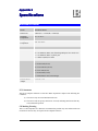
Appendix B
Specifica
Specifications
B
Broadband Router
Model
Broadband Router
Dimensions
204mm(L) * 127mm(W) * 29mm(H)
Operating
Temperature
0° C to 40° C
Storage
Temperature
-10° C to 70° C
Network Protocol:
TCP/IP
Network Interface:
6 Ethernet:
4 * 10/100BaseT (RJ45) auto-Switching Hub ports for LAN devices
1 * 10/100BaseT (RJ45) "Uplink" port
1 * 10BaseT (RJ45) for WAN
LEDs
11 LEDs
1 * WAN Link (Green)
4 * LAN Link/Act (Green)
4 * LAN 100 (Green)
1 * WAN Data (Green)
1 * Data/Status/LAN (Green/Orange)
External Power
Adapter
12 V DC, 1.5A
FCC Statement:
This device complies with Part 15 of the FCC Rules. Operation is subject to the following two
conditions:
(1) This device may not cause harmful interference.
(2) This device must accept any interference received, including interference that may
cause undesired operation.
CE Marking Warning
This is a Class B product. In a domestic environment this product may cause radio interference
in which case the user may be required to take adequate measures.
51