1
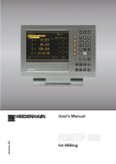
User's Manual
December 1994
TNC 122
Display
X
Y
X
PGM
LBL
SPEC
FCT
Program run
indicator
9
4
5
6
Z
1
2
3
CL
–
0
TOOL
DEF
R+/–
NO
ENT
STOP
8
Y
Z
MOD
7
Block number
ENT
DEL
F
X
HEIDENHAIN
Position displays
for the
coordinate axes
Y
X
Input line
Z
NO
ENT
7
8
9
Y
4
5
6
Z
1
2
3
Operating modes, Programming
POSITIONING Program
WITH MDI management
X
Y
Z
MOD
PGM
LBL
STOP
SPEC
FCT
X
7
8
9
Y
4
5
6
2
NO
ENT
Z
1
CL
–
0
TOOL
DEF
R+/–
3
MANUAL
OPERATION
Labels for subprograms
and program section
repeats
ENT
DEL
F
User parameters
MOD
HEIDENHAIN
PROGRAM RUN
SINGLE BLOCK
PROGRAM RUN
FULL SEQUENCE
PGM
LBL
STOP
SPEC
FCT
PROGRAMMING
& EDITING
Delete block;
abort function
DEL
F
Feed rate
Special
functions
Stop
Input in all modes of operation
X
Y
Z
MOD
PGM
LBL
STOP
SPEC
FCT
X
7
8
9
Y
4
5
6
2
NO
ENT
Z
1
CL
–
0
TOOL
DEF
R+/–
Coordinate axes
3
ENT
DEL
F
Incremental dimensions
X
7
8
9
Actual position capture
Y
4
5
6
NO
ENT
Z
1
2
3
CL
–
0
Numerical input
HEIDENHAIN
Clear entry
Reset entry
Change sign
Tool length and radius
ENT
Confirm entry
Decimal point
TOOL
DEF
R+/–
Change program block
Tool radius Program block selection
compensation
The TNC Guideline
From the workpiece drawing to
program-controlled machining
Step
Task
TNC mode
of operation
Starting
on page
Preparation
1
Select tools
——
——
2
Set workpiece datum
for coordinate system
——
——
Determine spindle speeds
and feed rates
——
——
4
Switch on TNC and machine
——
15
5
Cross over reference marks
6
Clamp workpiece
7
Set datum/
set position displays
3
15
——
——
21
Entering and testing part programs
8
9
10
Enter part program or
download over external
data interface
from 31
Test run: Run program block
by block without tool
51
If necessary:
Optimize the part program
from 31
Machining the workpiece
12
Insert tool and
run part program
51
TNC Accessory
Floppy disk unit
With the HEIDENHAIN FE 401 B floppy disk unit you can store
programs from the TNC on diskette.
It is also a means of transferring programs created on a personal
computer to the TNC.
The FE 401 B Floppy Disk Unit
Contents
Scope of this Manual ......................................................................................... 7
TNC 122 ............................................................................................................. 7
How to Use This Manual .................................................................................... 8
Dialog Flowcharts ............................................................................................... 8
Special Notes in This Manual ............................................................................. 9
1
Fundamentals of Positioning ................................................... 11
Reference system and coordinate axes ........................................................... 11
Datums and positions ...................................................................................... 12
Machine axis movements and position feedback ............................................ 14
2
Working with the TNC 122 – First Steps ................................. 15
Before you begin .............................................................................................. 15
Switch on the TNC ........................................................................................... 15
Operating modes ............................................................................................. 16
Error messages ................................................................................................ 16
Selecting the position display mode ................................................................. 17
3
Manual Operation and Setup ................................................... 19
Moving the machine axes with the axis direction buttons ............................... 19
Entering tool length and radius ......................................................................... 20
Setting the datum ............................................................................................ 21
4
Positioning with Manual Data Input (MDI) ............................. 23
5
Programming ............................................................................. 31
Entering the program number .......................................................................... 32
Deleting programs ............................................................................................ 32
Selecting program blocks ................................................................................. 33
Changing program blocks ................................................................................. 33
Deleting program blocks .................................................................................. 34
Feed rate F and miscellaneous function M ...................................................... 35
Entering a program interruption ....................................................................... 36
Entering workpiece positions ........................................................................... 37
Actual-position capture: Teach-In programming ............................................... 38
Hole patterns in programs ................................................................................ 39
Bolt hole circle .................................................................................................. 39
Linear hole patterns ......................................................................................... 41
Subprograms and Program Section Repeats ................................................... 43
Subprograms .................................................................................................... 44
Program section repeats .................................................................................. 46
Contents
Before you machine the part ............................................................................ 23
Taking the tool radius into account ................................................................... 23
Entering the miscellaneous function M ............................................................ 24
Entering and changing the feed rate F ............................................................. 24
Entering and moving to positions ..................................................................... 25
Hole patterns ................................................................................................... 27
Input for a bolt hole circle ................................................................................. 27
Input for linear hole patterns ............................................................................ 27
Drilling the hole pattern .................................................................................... 27
6
Transferring Programs over the Data Interface ...................... 49
Transferring a program to the TNC ................................................................... 49
Transferring programs out of the TNC ............................................................. 50
7
Executing Programs .................................................................. 51
Interrupting program run .................................................................................. 52
Single block ...................................................................................................... 52
Automatic ......................................................................................................... 52
8
User Parameters ........................................................................ 53
9
Tables and Overviews ............................................................... 55
Miscellaneous functions (M functions) ............................................................ 55
Pin layout and connecting cable for the data interface ..................................... 57
TNC Messages ................................................................................................. 58
Specifications ................................................................................................... 60
Accessory ........................................................................................................ 60
Subject Index ............................................................................. 61
Scope of this Manual
This manual describes the operation of the TNC 122 from the
software version
Progr. 246 xxx 01.
The three x's represent any numbers.
For detailed technical information, refer to the Technical
Manual for the TNC 122.
TNC 122
TNC-Familie
What is NC?
NC stands for Numerical Control, that is, control of a machine tool
by means of numbers. Modern controls such as the TNC have a
built-in computer for this purpose and are therefore called CNC
(Computerized Numerical Control).
From the very beginning, the TNCs from HEIDENHAIN were developed specifically for shop-floor programming by the machinist. This
is why they are called TNC, for “Touch Numerical Controls.”
The TNC 122 is a straight cut control for milling, drilling, and boring
machines with up to three axes.
Differences from the TNC 121
The TNC 122 features the following improvements over the
TNC 121:
• Larger program memory
• Tool compensation
• Programmable feed rate
• RS-232-C/V.24 data interface
Programming
Workpiece machining is defined in a part program. It contains a
complete list of instructions for machining a part, for example the
target position coordinates or the feed rate
TNC 122
7
How to Use This Manual
As a TNC beginner, you can use the operating instructions as a
step-by-step workbook. This part begins with a short introduction
to some important basics concepts, and provides an overview of
the available features. Then each feature is explained in detail,
using a practical example that you can immediately try out on the
machine — so you can't get lost in the theory. As a beginner you
should work through all the examples presented.
The examples are intentionally brief; it generally won't take you
longer than 10 minutes to enter the example data.
As a TNC expert, you can use this manual as a comprehensive
review and reference guide. The clear layout and the subject index
make it easy to find the desired topics.
Dialog Flowcharts
Dialog flowcharts are used for each example in this manual.
They are laid out as follows:
The operating mode is indicated above the first dialog flowchart.
This area shows the
keys to press.
This area explains the function of the key or the work step.
If necessary, supplementary information will also be included.
Prompt
This area shows the
keys to press.
This area explains the function of the key or the work step.
If necessary, supplementary information will also be included.
If there is an arrow at the end of the flowchart, this means that it
continues on the next page.
A prompt appears with some actions (not always) above the input
keypad.
Abbreviated flowcharts
Abbreviated flowcharts supplement the examples and
⇒) indicates a new input or a work step.
explanations. An arrow (⇒
8
TNC 122
Special Notes in This Manual
Especially important information is shown as a separate note in a
gray box. Pay special attention to these notes. Ignoring them
would prevent effective use of the control, or even result in
damage to the tool or workpiece.
Symbols in the gray boxes
The symbols in the left of the gray boxes indicate the nature of the
provided information.
General information
for example on the machine tool.function
Information for the machine tool builder
for example that he must implement a certain function
Essential information
for example that a certain tool is needed for the
described function
TNC 122
9
NOTES
10
TNC 122
1
Fundamentals of Positioning
1
Fundamentals of Positioning
Reference system and coordinate axes
Reference system
In order to define positions on a surface one needs a reference
system. For example, positions on the earth's surface can be
defined “absolutely” by their geographic coordinates of longitude
and latitude. The term “coordinate” comes from the Latin word for
“that which is arranged.” The network of horizontal and vertical
lines on the globe constitute an absolute reference system in contrast to the “relative” definition of a position that is referenced to
some other known location.
60°
Greenwich
30°
0°
30°
The illustration at right shows the 0° longitude at the Greenwich
observatory and the 0° latitude at the equator.
60°
90° 0° 90°
Fig. 1.1:
Cartesian coordinate system
On a milling or boring machine, workpieces are normally machined
according to a workpiece-based Cartesian coordinate system (a
rectangular coordinate system named after the French mathematician and philosopher Renatus Cartesius, who lived from 1596 to
1650). The Cartesian coordinate system is based on three coordinate axes designated X, Y and Z which are parallel to the machine
guideways.
+Y
The figure at right illustrates the “right-hand rule” for remembering
the three axis directions: the middle finger is pointing in the positive direction of the tool axis from the workpiece toward the tool
(the Z axis), the thumb is pointing in the positive X direction, and
the index finger in the positive Y direction. X, Y and Z are the main
axes of the Cartesian coordinate system.
+Z
+X
+Z
+X
+Y
Fig. 1.2:
TNC 122
The geographic coordinate system
is an absolute reference system
Designations and directions of the
axes on a milling machine
11
1
Fundamentals of Positioning
Datums and positions
Setting the datum
The workpiece drawing identifies a certain point on the workpiece
(usually a corner) as the “absolute datum” and perhaps one or
more other points as relative datums. The datum setting procedure
establishes these points as the origin of the absolute or relative coordinate systems: The workpiece, which is aligned with the machine axes, is moved to a certain position relative to the tool and
the display is set either to zero or to another appropriate value
(e.g., to compensate the tool radius).
Z
Y
X
Fig. 1.3:
Example: Coordinates of hole 1 :
X = 10 mm
Y=
5 mm
Z=
0 mm (hole depth: Z = – 5 mm)
The datum of the Cartesian coordinate system
is located 10 mm from hole 1 on the X axis and
5 mm from it in the Y axis (in negative direction).
The workpiece datum represents the
origin of the Cartesian coordinate
system
Z
Y
X
1
5
10
Fig. 1.4:
12
Hole defines the coordinate system
TNC 122
1
Fundamentals of Positioning
Datums and positions
Absolute workpiece positions
Each position on the workpiece is uniquely identified by its absolute coordinates.
:
1
1
Y
15
m
X
m
10
X=20m
Y=
If you are drilling or milling a workpiece according to a workpiece
drawing with absolute coordinates, you are moving the tool to the
value of the coordinates.
Z=15mm
Example: Absolute coordinates of the position
X =
20
mm
Y =
10
mm
Z =
15
mm
Z
m
10
20
Fig. 1.5:
Position definition through absolute
coordinates
Incremental workpiece positions
2
20
referenced to
Absolute coordinates of position 2 :
X =
10
mm
Y =
5
mm
Z =
20
mm
Incremental coordinates of position 3 :
IX=
10
mm
IY=
10
mm
IZ
=
–15 mm
IY
=1
0m
IX=10
m
mm
15
3
3
Y
10
Example: Incremental coordinates of position
position 2
Z
IZ=–15mm
A position can also be referenced to the preceding nominal position. In this case the relative datum is always the last programmed position. Such coordinates are referred to as incremental coordinates (increment = increase). They are also
called incremental or chain dimensions (since the positions are
defined as a chain of dimensions). Incremental coordinates are
designated with the prefix I.
X
5
5
10
10
0
0
Fig. 1.6:
Position definition through incremental coordinates
If you are drilling or milling a workpiece according to a drawing with
incremental coordinates, you are moving the tool by the value of
the coordinates.
TNC 122
13
1
Fundamentals of Positioning
Machine axis movements and position feedback
Programming tool movements
During workpiece machining, an axis position is changed either by
moving the tool or by moving the machine table on which the
workpiece is fixed.
+Z
+Y
+X
When entering tool movements in a part program you
always program as if the tool is moving and the workpiece is stationary.
Fig. 1.7:
Position feedback
The position feedback encoders convert the movement of the machine axes into electrical signals. The control evaluates these signals and constantly calculates the actual position of the machine
axes.
If there is an interruption in power, the calculated position will no
longer correspond to the actual position. When power is restored,
the TNC can re-establish this relationship with the aid of the encoders' reference marks.
On this machine the tool moves in
the Y and Z axes; the workpiece
moves in the X axis.
Z
Y
X
Fig. 1.8:
Reference marks
Linear position encoder, here for the
X axis
The scales of the position encoders have one or more reference
marks. When a reference mark is passed over, it generates a signal which identifies that position as the reference point (scale reference point = machine reference point). With the aid of this reference mark the TNC can re-establish the assignment of displayed
values to machine axis positions.
If the position encoders feature distance-coded reference marks,
each axis need only move a maximum of 20 mm (0.8 in.) for linear
encoders, and 20° for angle encoders.
Fig. 1.9:
14
Linear scales: above with distancecoded reference marks, below with
one reference mark
TNC 122
2
Working with the TNC 122 – First Steps
2
Working with the TNC 122 – First Steps
Before you begin
You must cross over the reference marks after every switch-on.
From the positions of the reference marks, the TNC automatically
re-establishes the relationship between axis slide positions and
display values that you last defined by setting the datum.
When you set a new datum point, the control automatically stores
the new relationship between axis positions and display values.
Switch on the TNC
0⇒1
Switch on the TNC and the machine tool.
MEMORY
Please wait...
POWER
CL
TEST
The TNC automatically checks its internal memory.
INTERRUPTED
Clear the TNC message indicating that the power was interrupted.
NO CONTROL VOLTG
Switch on the control voltage.
The TNC automatically checks the function of the EMERGENCY STOP button.
I
REF TRAV
ENT
ENT/NOE
Select reference mark evaluation.
REF MARK
XYZ
Press and hold:
X
Y
Cross the reference marks in any direction:
Press and hold the machine axis direction button until the moving
axis disappears from the screen.
Sequence in this example: X axis, Y axis, Z axis
Z
The TNC 122 is now ready for operation in the
MANUAL OPERATION mode.
If you do not wish to cross over the reference marks:
⇒ Answer the REF TRAV ENT/NOE dialog prompt with NO ENT
(this feature must be implemented by the machine tool
builder).
TNC 122
15
2
Working with the TNC 122 – First Steps
Operating modes
Selecting an operating mode makes a specific group of functions
available.
Usable functions
Operating mode Key
Moving the machine axes;
Setting the datum
MANUAL
OPERATION
Entering positioning blocks
and executing them block
by block;
Changing feed rate and
miscellaneous functions;
Entering tool data
POSITIONING
WITH MANUAL
DATA INPUT
Storing working steps for
small-lot production by
• Keyboard entry
• Teach-In
Transferring programs
through the data interface
PROGRAMMING
AND EDITING
Running programs
blockwise
SINGLE BLOCK
Running programs
continuously
AUTOMATIC
You can switch to another operating mode at any time by pressing key for the desired mode.
Error messages
If an error occurs while you are operating the TNC, a message will
appear in plain language. You will find an overview of error message in Chapter 9.
To clear an error message:
⇒ Press the CL key.
Blinking error messages
WARNING!
A blinking error messages means that the operational
reliability of the TNC has been impaired.
If the TNC shows a blinking error message:
⇒ Write down the message.
⇒ Switch off the TNC and the machine tool.
⇒ Try to correct the error with the power off.
⇒ If the error cannot be corrected or if a blinking error message
persists, call your service representative.
16
TNC 122
2
Working with the TNC 122 – First Steps
Selecting the position display mode
The TNC can show different types of position values for a tool
position.
1
2
Fig 2.1 shows the following positions
• Starting position A of the tool
• Target position Z of the tool
• Workpiece datum W
• Scale reference point M
The TNC position display can be set to show the following types of
information:
• Actual position 2
The position at which the tool is presently located as referenced to the workpiece datum.
• Servo lag 3
The difference between nominal 1 and actual 2 positions
• Actual position referenced to the scale reference point 4
3
Z
A
W
4
M
Fig 2.1:
Tool and workpiece positions
To change position display modes:
⇒ Set another position display mode in the user parameter
MP 7322 (see Chapter 8).
TNC 122
17
2
Working with the TNC 122 – First Steps
NOTES
18
TNC 122
3
Manual Operation and Setup
3
Manual Operation and Setup
The TNC 122 provides two methods for manually moving the machine axes:
• Axis direction buttons
• Positioning with Manual Data Input (see Chapter 4)
Changing the feed rate F
Some machines are equipped with a potentiometer to enable you
to vary the feed rate.
Moving the machine axes with the axis direction buttons
In the MANUAL OPERATION mode you can move a machine axis
by pressing the appropriate axis direction button on the machine
control panel. As soon as you release the button the axis stops.
Continuing machine axis movement
With the user parameter MP7680 (see Chapter 8) you can set the
TNC for continuing machine axis movement. The machine then
continues to move the axis after you have released the axis direction button. To stop the machine axis you must press a button
again (see example 2 below).
Example: Moving the machine axis with the machine axis direction
button in the Z+ direction (retracting the tool)
Z
Y
X
Example 1: Moving the machine axis
Mode of operation: MANUAL OPERATION
Press and hold:
Press the direction button, e.g. Z, and hold it as long as you wish the machine
axis to move.
Z
Example 2: Moving the machine axis (continuing movement)
Mode of operation: MANUAL OPERATION
Z
Together:
0
TNC 122
I
To start the axis, press an axis direction button, such as Z, and the NC start
button at the same time.
Stop the axis with the NC stop button.
19
3
TOOL
DEF
Manual Operation and Setup
Entering tool length and radius
You can enter the length and radius of you tool in the TNC. The
TNC includes the tool radius in the position value when you position with radius compensation (see p. 21).
The tool length is the difference in length ∆L between the tool and
the zero tool.
Z
T1
T2
T3
R2
R1
R3
Sign for the length difference ∆L
If the tool is longer than the zero tool: ∆L > 0
If the tool is shorter than the zero tool: ∆L < 0
∆L3<0
Position display in the tool axis
∆L1=0
User parameter MP7285 defines whether the tool axis display
value shows the position of the tool tip or the tool datum.
Checking the tool data
To display the tool data:
⇒ Press the TOOL DEF key.
To display the tool length and tool axis:
⇒ Press the downward-arrow key twice.
To return to the position display:
⇒ Press the NO ENT key.
Fig. 3.1:
X
∆L2>0
Tool lengths and radii
Example: Entering the tool length and radius
Tool radius:
8 mm
Tool length:
12 mm
Tool axis:
Z
Z
T0
T7
R7
L0=0
X
L7>0
Call the tool definition function.
TOOL
DEF
R A D I U S = .....
8
Enter the tool RADIUS ( 8 mm ). Confirm your entry.
ENT
L E N G T H = .....
2
1
ENT
Enter the tool LENGTH ( 12 mm ). Confirm your entry.
AXIS=.
Z
20
ENT
Enter the tool AXIS ( Z ). Confirm your entry.
TNC 122
3
Manual Operation and Setup
Setting the datum: Moving to the datum surface and entering the actual value
To set the datum, you move the tool to the respective datum surfaces and enter the tool position as datum.
Example: Setting the datum in the X and Z axes
Z
Working plane:
X / Y
Tool axis:
Z
Tool radius:
R = 5 mm
Sequence for
datum setting
in this example:
Y
X, Z
1
Procedure
X
⇒ Insert the tool.
⇒ Enter the tool data.
⇒ Switch on the spindle, e.g. with the miscellaneous
function M 3.
Mode of operation: MANUAL OPERATION
Touch surface
1
with the tool.
Select the X axis.
X
DATUM
X =
5
ENT
X=
Enter the position of the tool center (X = – 5 mm)
and
transfer the X coordinate of the datum.
Touch the top surface with the tool.
Select the Z axis.
Z
DATUM
Z =
0
ENT
TNC 122
Z=
Enter the position of the tool tip (Z = 0 mm)
and
transfer the Z coordinate to the display.
21
3
Manual Operation and Setup
NOTES
22
TNC 122
4
Positioning with MDI
4
Positioning with Manual Data Input (MDI)
For many simple machining tasks, for example if a part is to be machined only once, or if you are machining simple geometrical
shapes, it would be too time consuming to enter the individual machining steps in an NC program.
In the POSITIONING WITH MDI mode of operation you can execute the working steps as you enter them instead of storing them
in a part program.
Simple milling and drilling operations
Enter the following nominal position data manually in the POSITIONING WITH MDI mode of operation:
• Coordinate axis
• Position value
• Radius compensation
The TNC then moves the tool to the desired position.
Hole patterns
he POSITIONING WITH MDI mode of operation also supports the
TNC "Cycles" (see Chapter 5):
• Bolt hole circle patterns
• Linear hole patterns
Before you machine the part
⇒ Insert the tool.
⇒ Pre-position the tool so that the tool and workpiece will not be
damaged during workpiece approach.
⇒ Select an appropriate feed rate F.
⇒ Select an appropriate spindle speed S.
⇒ Switch on the spindle, e.g. with the miscellaneous function
M3.
Taking the tool radius into account
Y
R0
The TNC can compensate the tool radius (see Fig. 4.1). This allows
you to enter workpiece dimensions directly from the drawing. The
TNC automatically lengthens (R+) or shortens (R–) traverse by the
tool radius.
R+
Entering tool data
R–
⇒ Press the TOOL DEF key
⇒ Enter in sequence the tool radius, length, and axis.
X
Fig. 4.1:
TNC 122
Tool radius compensation
23
4
Positioning with MDI
Entering and changing the feed rate F
Example: Enter the feed rate F
Select the feed rate function F for the next tool movement.
F
F
1
0
0
F blinks:
Enter the feed rate F, e.g. 100 mm/min.
Confirm feed rate F for the next tool movement.
ENT
Changing the feed rate F
Some machines are equipped with a potentiometer to allow you to
vary the feed rate.
Entering the miscellaneous function M
The machine tool builder determines which miscellaneous
functions are available on your TNC and what effect they
have.
Press the SPEC FCT key for special functions.
SPEC
FCT
Page to M FUNCTION.
Repeatedly
M
FUNCTION
Select M FUNCTION.
ENT
M
3
ENT
I
24
0
M blinks: Enter the desired M function, e.g. M3 (spindle on, clockwise).
Confirm your entry.
Execute the M function.
TNC 122
4
Positioning with MDI
Entering and moving to positions
For simple tasks, use the POSITIONING WITH MDI mode of operation
to machine the dimensions as you enter them.
Example: Milling a shoulder
Y
4
X = 0 mm
X = 30 mm
X = 30 mm
X = 60 mm
Y = 20 mm
Y = 20 mm
Y = 50 mm
Y = 50 mm
1
0
Procedure:
⇒ Enter the tool data.
⇒ Move the tool to a good starting position
(e.g. X = Y = – 20 mm).
⇒ Move the tool to the milling depth.
2
0
X
60
3
:
:
:
:
4
30
1
2
20
Corner
Corner
Corner
Corner
3
50
The coordinates are entered as absolute dimensions referenced to
the workpiece datum.
Mode of operation: POSITIONING WITH MDI
Select the Y axis.
Y
Y
2
0
R +/–
ENT
1
: Y = + 20 mm,
Move the tool to the programmed position.
I
Select the X axis.
X
X
3
0
R +/–
ENT
I
TNC 122
R 0
Y blinks:
Enter the nominal position for corner point
select the tool radius compensation: R +
and confirm your entry.
R 0
X blinks:
Enter the nominal position for corner point
select the tool radius compensation: R –
and confirm your entry.
2
: Y = + 30 mm,
Move the tool to the programmed position.
25
4
Positioning with MDI
Entering and moving to positions
Select the Y axis.
Y
Y
5
0
R +/–
ENT
Y blinks:
Enter the nominal position for corner point
Select tool radius compensation: R + and
confirm your entry.
I
Move the tool to the entered position.
X
Select the X axis.
X
6
0
R +/–
ENT
I
26
R 0
3
: Y = +50 mm,
4
: Y = +60 mm,
R 0
X blinks:
Enter the nominal position for corner point
Select tool radius compensation: R + and
confirm your entry.
Move the tool to the entered position.
TNC 122
4
Positioning with MDI
Hole patterns
The hole pattern functions BOLT HOLE CIRCLE and LINEAR
PATTERN are provided in the POSITIONING WITH MDI mode of
operation.
You select the BOLT HOLE CIRCLE or LINEAR HOLE PATTERN
function and enter the necessary data. This data, such as the
number of holes and the coordinates of the first hole, is normally
shown on the production drawing.
The TNC calculates the positions of the holes.
Pre-positioning the drill
You pre-position the drill in the Z axis above the surface of the
workpiece. The TNC positions the drill in the X and Y axes (in the
working plane) above each hole position.
Hole depth
If you wish to use a spindle sleeve to drill the holes manually:
⇒ Answer the dialog prompt DEPTH = with NO ENT.
Input for a bolt hole circle
•
•
•
•
•
•
Full circle or circle segment
Number of holes
Center point coordinates and radius of the circle
Starting angle (angular position of first hole)
For circle segment: angle step between the holes
Hole depth
Input for linear hole patterns
•
•
•
•
•
•
•
Coordinates of the first hole
Number of holes per row
Spacing between holes on a row
Angle between the first row and the angle reference axis
Number of rows
Spacing between rows
Hole depth
Drilling the hole pattern
After you have entered all the data:
⇒ Press the NC start key repeatedly.
The TNC moves the axes one at a time in the working plane and
the tool axis. After drilling it returns the tool to the starting height.
Skipping holes
If you wish to skip certain holes, or bore in a different sequence
than that calculated by the TNC:
⇒ Select the desired hole with the upward and downward arrow
keys.
TNC 122
27
4
Positioning with MDI
Hole patterns
Example: Entering and machining a bolt hole circle
Y
30°
R2
0
mm
mm
mm
50
8
X = 50
Y = 50
Bolt hole circle radius:
20
Starting angle: Angle between
the X axis and the first hole:
30°
Hole depth:
8
mm
50
0
0
Number of holes:
Center point coordinates:
X
Mode of operation: POSITIONING WITH MDI
Press the SPEC FCT key for special functions.
SPEC
FCT
Repeatedly
Page to the BOLT HOLE CIRCLE function.
B O L T
Repeatedly
Page to the FULL CIRCLE function.
F U L L
C I R C L E
Select FULL CIRCLE
ENT
N O
H L =
Enter the number of holes NO HL ( 8 ).
Confirm your entry and continue the dialog.
8
C E N T
0
0
X =
Enter the X coordinate of the bolt hole circle center ( X = 50 mm ).
Confirm your entry and continue the dialog.
C E N T
5
C I R C L E
Select the BOLT HOLE CIRCLE function.
ENT
5
H O L E
Y =
Enter the Y coordinate of the bolt hole circle center ( Y = 50 mm ).
Confirm your entry and continue the dialog.
R A D I U S =
2
0
Enter the RADIUS of the bolt hole circle ( 20 mm ).
Confirm your entry and continue the dialog.
A N G L E =
3
28
0
Enter the starting ANGLE from the X axis to the first hole ( 30° ).
Confirm your entry and continue the dialog.
TNC 122
4
Positioning with MDI
Hole patterns
D E P T H =
Enter the hole DEPTH ( 8 mm ).
Confirm your entry and continue the dialog.
8
B O L T
H O L E
C I R C L E
?
Start the bolt hole circle.
ENT
C Y C L
F U L L
I
C I R C L E
Start the FULL CIRCLE cycle.
B L T
C I R
I
Repeatedly
H O L E
1
...
For each hole move the axes in the working plane and drill until all holes in the
full circle are completed.
Example: Entering and machining linear hole patterns
Y
X = 20 mm
Y = 15 mm
4
10 mm
12
18°
1
0
18°
3
12 mm
8 mm
10
15
X coordinate of hole 1
Y coordinate of hole 1
Number of holes per row
Hole spacing
Angle between rows and
X axis
Number or rows
Row spacing
Hole depth:
20
0
X
Mode of operation: POSITIONING WITH MDI
SPEC
FCT
Press the SPEC FCT key for special functions.
Repeatedly
Page to the LINEAR PATTERN function.
L I N E A R
ENT
H . 1
2
TNC 122
0
P A T T E R N
Select the LINEAR PATTERN function.
X =
Enter the X coordinate of hole 1 ( X = 20 mm ).
Confirm your entry and continue the dialog.
29
4
Positioning with MDI
Hole patterns
H . 1
1
Y =
Enter the Y coordinate of hole
5
N O
( Y = 15 mm ).
H L =
Enter the number of holes per row ( 4 ).
4
H L .
1
1
S P C =
Enter the spacing between holes in the row (10 mm).
0
A N G L E =
1
Enter the ANGLE between the X axis and the hole pattern (18°).
8
D E P T H =
Enter the DEPTH of the holes ( 8 mm ).
8
N O .
R W =
3
Enter the number of rows ( 3 ).
R W .
1
S P C =
Enter the spacing between rows (12 mm).
2
S T A R T
C Y C L
I
L I N E A R
P A T T
Start the LINEAR PATTERN cycle.
L I N R .
30
P A T T ?
Start the linear hole pattern.
ENT
Repeatedly
L I N .
I
H O L E
1
...
For each hole move the axes in the working plane and drill until all holes in the
linear pattern are completed.
TNC 122
5
Programming
5
Programming
In the PROGRAMMING AND EDITING mode of operation you can
store the individual work steps required for recurring machining
operations, for example in small-lot production.
Programs in the TNC
The part programs stored in the TNC contain the working steps for
machining a part. You can edit, add to and run these programs as
often as you wish.
You can store programs on floppy disk with the HEIDENHAIN
FE 401 floppy disk unit and load them into the TNC again on demand — you don't need to retype them. You can also transfer programs to a personal computer or printer.
Program storage capacity
The TNC 122 stores up to 20 programs with a maximum of 500 NC
blocks. A single program can contain up to 500 NC blocks.
Programmable functions
•
•
•
•
•
•
•
•
Interrupt the program (STOP)
Feed rate F
Miscellaneous function M
Nominal position values
Teach-In: capturing the actual position
Bolt hole circle and linear hole patterns
Program section repeats:
A section of a program only has to be entered once and can
then be run up to 999 times in succession.
Subprograms:
A section of a program only has to be entered once and can
then be run at various places in the program.
Tool and workpiece movement
During workpiece machining, the machine moves an axis by moving either the tool or the machine table on which the workpiece is
fixed.
When entering tool movements in a part program you
always program as if the tool is moving and the workpiece is stationary.
Pre-positioning the tool
Preposition the tool to prevent the possibility of damaging the tool
or workpiece. The best pre-position lies on the extension of the
tool path.
What happens with the completed programs?
The completed program is used to machine the part in the PROGRAM RUN mode of operation. See Chapter 7 for an explanation
of this mode.
TNC 122
31
5
Programming
Entering the program number
Select a program with a number from 1 to 20.
Mode of operation: PROGRAMMING AND EDITING
Select program management.
PGM
ENT
E D I T
ENT
P G M
7
ENT
Switch to the EDIT PGM function.
P G M
Select the EDIT PGM function.
N O .
=
The equal sign blinks: Enter the PGM-NO., for example 7.
Confirm your entry. Now you can enter and edit the program.
The BEGIN block of the selected program appears.
Deleting programs
If you no longer need certain programs, or if you need to make
space in the TNC's memory, you can delete programs.
Mode of operation: PROGRAMMING AND EDITING
Select program management.
PGM
Switch to the DELETE PGM function.
D E L E T E
ENT
P G M
5
ENT
P G M
Select the DELETE PGM function.
N O .
=
The equals sign blinks: enter the PGM NO. 5 to erase program 5.
After deletion the BEGIN block of the deleted program appears.
The contents of the program is deleted and the BEGIN and END
blocks of the deleted program remain in the TNC's memory.
Erase all programs
⇒ Use the upward arrow key to go from the DELETE PGM function to the DELETE ALL PGM function.
⇒ Press ENT to erase all programs.
32
TNC 122
5
Programming
Selecting program blocks
Current block
The current block appears in the entry line above the numeric keypad. The block number appears to the right and above the entry
line.
The TNC inserts new blocks behind the current block. No more
blocks can be entered if the END PGM block appears in the entry
line
Overview of functions
Function
Key
Select the next block
Select the previous block
Go directly to a program block
In large programs it can take a long time to scroll to the desired
block using the arrow keys. A quicker way is to use the GOTO
function to go directly to the desired block.
⇒ Enter the number of the desired block.
⇒ Confirm your entry with the ENT key.
The desired block appears in the entry line.
Changing program blocks
You can make changes in program blocks the incorrect numerical
entries in a program.
Clearing incorrect numerical entries
If you notice an incorrect numerical entry immediately after you've
made it, you can clear it and try again:
⇒ Press the CL key.
Confirming a change
Any change made with CL must be confirmed with ENT to become effective!
Example: Changing a program block
Mode of operation: PROGRAMMING AND EDITING
/
Move to the program block that you wish to change.
Select the block for editing.
The display (e.g. the axis designation) starts blinking.
2
0
ENT
TNC 122
Enter the desired change, for example a new nominal position value ( 20 ).
Confirm the change.
33
5
Programming
Deleting program blocks
You can delete any blocks in an existing program except the
BEGIN and END blocks
To delete a block:
⇒ Use the arrow keys to move to the block, or enter the block
number.
⇒ Press the DEL
key.
When a block is deleted, the TNC automatically renumbers the remaining blocks. The block before the deleted block becomes the
current block.
It is also possible to delete an entire program section:
⇒ Select the last block of the program section.
⇒ Press the DEL
key repeatedly until all the blocks in the
section have been deleted.
34
TNC 122
5
Programming
Feed rate F and miscellaneous function M
The feed rate F and miscellaneous function M are entered as
separate blocks. They become effective as soon as the TNC has
run the block in which they are programmed.
These blocks must be run before the positioning blocks for which
they are intended.
Entering the feed rate F
The machining feed rate is “modal.” That means that the entered
feed rate remains effective until you replaced it by entering a new
one.
Example
Mode of operation: PROGRAMMING AND EDITING
Press the F key for feed rate.
A blinking F appears.
F
F E E D
1
0
ENT
0
R A T E
F
Enter the desired feed rate F , for example 100 mm/min.
Confirm the feed rate F for the following positioning blocks.
Varying the feed rate
Some machines are equipped with a potentiometer to enable you
to vary the feed rate.
TNC 122
35
5
Programming
Feed rate F and miscellaneous function M
Entering the miscellaneous function M
The machine tool builder determines which miscellaneous
functions are available on your TNC and what effect
they have.
Example: Entering a miscellaneous function
Mode of operation: PROGRAMMING AND EDITING
SPEC
FCT
Press the SPEC FCT key for special functions.
Page to M FUNCTION.
Repeatedly
M
ENT
FUNKTION
Select M FUNCTION.
M
3
Enter the miscellaneous function e.g. M3 (Spindle ON, clockwise).
ENT
Confirm your M function entry.
Entering a program interruption
You can divide your program into logical sections by setting stop
blocks. The TNC interrupts the program at the stop block and
resumes it when you press a button.
Mode of operation: PROGRAMMING AND EDITING
STOP
Enter the STOP block in the program.
To restart a program after an interruption
⇒ Press the NC-Start button
36
TNC 122
5
Programming
Entering workpiece positions
Programming example: milling a shoulder
Y
1
X
60
Summary of programming steps
⇒ Press the PGM key.
⇒ Key in the number of the program you want to work on,
and press ENT.
⇒ Enter the nominal positions.
2
30
4
0
3
Y = 20 mm
Y = 20 mm
Y = 50 mm
Y = 50 mm
20
X = 0 mm
X = 30 mm
X = 30 mm
X = 60 mm
1
2
4
0
Corner
Corner
Corner
Corner
3
50
The coordinates are programmed in absolute dimensions.
The datum is the workpiece zero.
Running a completed program
Once a program has been completed it can be executed in the
PROGRAM RUN mode (see Chapter 10).
Example:
Entering a nominal position in a program
(Block 9 in the example)
X
Select the coordinate axis ( X axis ).
X
3
0
R +/–
ENT
R 0
Enter the nominal position value, for example 30 mm
and
select tool radius compensation R – .
Confirm your entry. The nominal position now appears in the program block
display.
Program blocks
TNC 122
0
1
2
3
4
5
6
7
8
BEGIN PGM 10
F 9999
Z+20.000
X–20.000
Y–20.000
Z–10.000
F 200
M 3
Y+20.000
9
X+30.000
R–
10
11
12
13
14
15
Y+50.000
X+60.000
F 9999
Z+20.000
M 2
END PGM 10
R+
R+
R0
R0
R+
Start of program, program number
High feed rate for pre-positioning
Clearance height
Pre-position the tool in the X axis
Pre-position the tool in the Y axis
Move tool to milling depth
Machining feed rate
Spindle ON, clockwise
Y coordinate, corner 1
X coordinate, corner 2
Y coordinate, corner 3
X coordinate, corner 4
High feed rate for retracting
Clearance height
Stop program run, spindle OFF, coolant OFF
End of program, program number
37
5
Programming
Actual-position capture: Teach-In programming
With teach-in programming, you enter the position values by moving to the position and then transferring the actual position value
into the program.
Changing the captured position values
Teach-in blocks can be edited later just like any other program
blocks.
Selecting radius compensation
If you wish to change the radius compensation:
⇒ Press the R +/– key.
Z
Programming example: Capturing a Z-coordinate value (top surface
of workpiece) for a part program
Y
X
Mode of operation: PROGRAMMING AND EDITING
Move the tool until it touches the surface of the workpiece.
Select the axis, for example Z.
Z
Z
Capture the position of the tool point for the program.
ENT
38
Store the position in the tool axis ( Z ).
TNC 122
5
Programming
Hole patterns in programs
The BOLT HOLE CIRCLE and LINEAR PATTERN cycles can
also be entered in a part program and saved for repeated execution. Each item of information then comprises its own program
block.
These blocks are introduced by a block with a block number, followed by the word CYCL and the name of the cycle. The cycles
contain all information required by the TNC for machining a hole
pattern.
The TNC executes a hole pattern automatically as soon as it
reaches the cycle in the program.
Cycles must be complete
Do not delete any blocks from the cycle. If you do, it will provoke
the error message CYCLE INCOMPLETE when the program is
executed.
Entering cycles
Press the SPEC FCT key and select the desired cycle. The TNC
automatically asks for all data required to execute the cycle.
Bolt hole circle
Y
R2
0
50
30°
50
0
0
Programming example: FULL CIRCLE cycle
Number of holes NO.HL :
8
Center point coordinates:
CENT X = 50 mm
CENT Y = 50 mm
Bolt hole circle radius RADIUS : 20 mm
Starting angle between X axis
and first hole ANGLE :
30°
Drilling depth DEPTH :
– 8 mm
X
Mode of operation: PROGRAMMING AND EDITING
SPEC
FCT
Repeatedly
Page to the BOLT HOLE CIRCLE function.
B O L T
ENT
F U L L
ENT
TNC 122
Press the SPEC FCT key for special functions.
H O L E
C I R C L E
Select the BOLT HOLE CIRCLE function.
C I R C L E
Select FULL CIRCLE
39
5
Programming
Bolt hole circle
NO. H L=
8
Enter the number of holes ( NO.HL = 8 ).
Confirm your entry.
ENT
CENT X =
5
0
CENT
5
Enter the X coordinate of the bolt circle center ( X = 50 mm ).
Confirm your entry.
ENT
0
Y =
Enter the Y coordinate of the bolt circle center ( Y = 50 mm ).
Confirm your entry.
ENT
RADIUS =
2
0
Enter the RADIUS of the bolt hole circle ( 20 mm ).
Confirm your entry.
ENT
ANGLE=
3
0
Enter the ANGLE from the X axis to the first hole ( 30° ).
Confirm your entry.
ENT
DEPTH =
8
ENT
Enter the DEPTH of the holes ( – 8 mm ).
Confirm your entry.
Program blocks
MM
Start of program, program number, unit of measurement
0
BEGIN PGM 40
1
2
3
F 9999
Z+20.000
M 3
High feed rate for pre-positioning
Clearance height
Spindle ON, clockwise
4
5
6
7
8
9
10
CYCL FULL CIRCLE
NO.HL = 8
CENT X= 50.000
CENT Y= 50.000
RADIUS= 20.000
ANGLE= 30.000
DEPTH= – 8.000
The data for the FULL CIRCLE cycle follow this block
Number of holes
X coordinate of the center of the bolt circle
Y coordinate of the center of the bolt circle
Radius
Starting angle of first hole
Depth of holes
11
M 2
Stop program run, spindle STOP, coolant OFF
12
END PGM 40
MM
End of program, program number, unit of measurement
For a circle segment ( CYCL CIRCL SEGMT ) you also
enter the angle step (ANGLE) between the holes (after the
starting angle).
The bolt hole circle is then executed in the PROGRAM RUN mode of operation (see Chapter 7).
40
TNC 122
5
Programming
Linear hole patterns
Programming example: LINEAR PATTERN cycle
X coordinate of the first hole 1
H.1 X = 20 mm
Y coordinate of the first hole 1
H.1 Y = 15 mm
Number of holes per row NO.HL
4
Hole spacing HL.SPC
10 mm
Angle between hole row
and X axis ANGLE
18°
DEPTH of holes
– 8 mm
Number of rows NO.RW
3
Row spacing RW.SPC
12 mm
Y
10
12
15
18°
0
1
20
0
X
Mode of operation: PROGRAMMING AND EDITING
Press the SPEC FCT key for special functions.
SPEC
FCT
BOLT
H O L E
C I R C L E
?
Select BOLT HOLE CIRCLE.
ENT
H . 1 X =
2
0
ENT
Enter the X coordinate of hole
Confirm your entry.
1
( X = 20 mm ).
Enter the Y coordinate of hole
Confirm your entry.
1
( Y = 15 mm ).
H . 1 Y =
1
5
ENT
N O .
4
H L =
ENT
Enter the number of holes per row (NO.HL = 4 ).
Confirm your entry.
HL . S P C =
1
0
ENT
Enter the hole spacing in the row (HL.SPC = 10 mm).
Confirm your entry.
ANGLE =
1
TNC 122
8
ENT
Enter the ANGLE between the X axis and the rows of holes (ANGLE = 18°).
Confirm your entry.
41
5
Programming
Linear hole patterns
DEPTH =
8
ENT
Enter the DEPTH of the holes ( – 8 mm ).
Confirm your entry.
NO. R W =
3
ENT
Enter the number of rows (NO.RW = 3 ).
Confirm your entry.
R W . S P C =
1
2
ENT
Enter the spacing between rows ( RW.SPC = 12 mm ).
Confirm your entry.
Program blocks
0
BEGIN PGM 50
Start of program, program number
1
2
3
F 9999
Z+20.000
M 3
High feed rate for pre-positioning
Clearance height
Spindle ON, clockwise
4
5
6
7
8
9
10
11
12
CYCL LINEAR PATT
H.1 X= 20.000
H.1 Y= 15.000
NO.HL= 4
HL.SPC= 10.000
ANGLE= 18.000
DEPTH= –8.000
NO.RW= 3
RW.SPC= 12.000
The data for the LINEAR PATTERN cycle follow this block
X coordinate of first hole
Y coordinate of first hole
Number of holes per row
Distance between holes on the row
Angle between the rows and the X axis
Depth of the holes
Number of rows
Spacing between rows
13
M 2
Stop program run, spindle STOP, coolant OFF
14
END PGM 50
End of program, program number
The hole pattern is then executed in the PROGRAM RUN mode of operation (see Chapter 7).
42
TNC 122
5
Programming
Subprograms and Program Section Repeats
Subprograms and program section repeats only need to be entered
once in the program. You can then run them up to 999 times.
0 BEGIN PGM ...
.
1
.
.
. CALL LBL 1
.
.
3
.
. L Z + 100 M2
. LBL 1
.
.
2
.
Subprograms can be run at any point in the program, while program section repeats are run several times in succession.
Inserting program markers (labels)
You identify subprograms and program section repeats with labels
(abbreviated in the program to LBL).
Labels 1 to 99
Labels 1 to 99 identify the beginning of a subprogram or a program
section that is to be repeated.
LBL 0
END PGM ...
Label 0
Label 0 is used only to identify the end of a subprogram.
Label call
Subprogram and program sections are called within the program
with a CALL L command.
The command CALL L 0 is not allowed.
Subprograms:
When it reaches a CALL L block, the TNC immediately executes
the called subprogram.
Program section repeats:
The TNC repeats the program section above the CALL L block.
Together with the CALL L command you also enter the number
of desired repetitions.
Nesting
You can run subprograms and repeat program sections within
other subprograms and program sections. This is called nesting.
An example of nesting is when you call a subprogram from within
another subprogram.
Maximum nesting depth: 8 levels
TNC 122
Fig 8.1:
0
.
.
.
.
.
.
.
.
.
.
.
.
Operating sequence of a
subprogram
BEGIN PGM ...
1
LBL 1
2
R
3
R
4
CALL LBL 1 REP 2/2
5
END PGM ...
Fig. 8.2:
Operating sequence of a program
section repeat
43
5
Programming
Subprograms
This example requires a center-cut end mill (ISO 1641).
Y
20
Programming example: Subprogram for slots
Slot lengths:
20 mm + tool diameter
Slot depths:
– 10 mm
Slot diameters:
8 mm (= tool diameter)
Infeed point coordinates
Slot 1
X = 20 mm
Y = 10 mm
Slot 2
X = 40 mm
Y = 50 mm
Slot 3
X = 60 mm
Y = 40 mm
8
50
2
40
3
10
X
60
40
20
Example: Inserting a label for a subprogram
0
0
1
Mode of operation: PROGRAMMING AND EDITING
Select the LBL function.
LBL
S E T = E N T / C A L L = L B L
Select SET to set a label.
ENT
L B L
5
ENT
...
Enter a label number.
Confirm your entry. The resulting program block is: LBL 5
The beginning of a subprogram (or a program section repeat) is
now marked with the label. Enter the program blocks for the subprogram after the LBL block.
Label 0 (LBL 0) is used only to identify the end of a subprogram.
Example: Entering a subprogram call: CALL L
Mode of operation: PROGRAMMING AND EDITING
Select the LBL function.
LBL
S E T = E N T / C A L L = L B L
Select CALL to call a label.
LBL
5
NO
ENT
44
C A L L
L 0
ENT
Enter the label number of the desired subprogram.
Confirm your entry.
C A L L
L 5
R
R stands for “repetitions” and has no significance for subprogramming. Skip
this prompt by pressing NO ENT. The resulting program block is: CALL L5
TNC 122
5
Programming
Subprograms
After a CALL L block in the operating mode PROGRAM RUN, the
TNC executes those blocks in the subprogram that are located between the LBL block with the called number and the next block
containing LBL 0.
Program blocks
TNC 122
0
BEGIN PGM 60
Start of program, program number
1
2
3
4
5
F 9999
Z+20.000
X+20.000
Y+10.000
M 3
High feed rate for pre-positioning
Clearance height
X coordinate infeed point slot 1
Y coordinate infeed point slot 1
Spindle ON, clockwise
6
CALL L 1
7
8
9
X+40.000
Y+50.000
CALL L 1
R0
R0
X coordinate infeed point slot 2
Y coordinate infeed point slot 2
Call subprogram 1: execute blocks 16 to 20
10
11
12
X+60.000
Y+40.000
CALL L 1
R0
R0
X coordinate infeed point slot 3
Y coordinate infeed point slot 3
Call subprogram 1: execute blocks 16 to 20
13
14
Z+20.000
M 2
Clearance height
Stop program run, spindle STOP, coolant OFF
15
16
17
18
19
20
21
LBL 1
F 200
Z–10.000
IY+20.000
F 9999
Z+2.000
LBL 0
Start of subprogram 1
Machining feed rate during subprogram
Infeed to slot depth
Mill slot
High feed rate for retracting and pre-positioning
Retract
End of subprogram 1
22
END PGM 60
R0
R0
Call subprogram 1: execute blocks 16 to 20
R0
End of program, program number
45
5
Programming
Program section repeats
A program section repeat is entered like a subprogram. The end of
the program section is identified simply by the command to repeat
the section.
Label 0 is therefore not set.
CALL LBL block for a program section repeat
Example of a call label block: CALL L 1
R10 / 10 .
The two numbers with the slash between them indicate that this is
a program section repeat. The number in front of the slash is the
number of repetitions you programmed. The number behind the
slash is the number of repetitions remaining to be run.
Y
70
16
6
Programming example: Program section repeat for slots
Slot lengths
16 mm + tool diameter
Slot depths
– 12 mm
Incremental offset
of the infeed point 15 mm
Slot diameter
6 mm (= tool diameter)
Infeed point coordinates
Slot 1
X = 30 mm
Y = 10 mm
55
40
25
10
1
30
Example: Label for a program section repeat
0
0
This example requires a center-cut end mill (ISO 1641).
X
Mode of operation: PROGRAMMING AND EDITING
Select the LBL function.
LBL
S E T = E N T / C A L L = L B L
Select SET to set a label.
ENT
L B L
5
ENT
...
Enter the label number.
Confirm your entry. The resulting program block is LBL 5
Enter the blocks for the program section repeat after the
LBL block.
46
TNC 122
5
Programming
Program section repeats
Example: Entering a program section repeat: CALL L
Select the LBL function.
LBL
S E T = E N T / C A L L = L B L
Select CALL to call the label.
LBL
C A L L
5
4
L 0
ENT
Enter the label number.
Confirm your entry.
C A L L
L 5
ENT
Enter the desired number of repetitions R, for example 4.
Confirm your entry. The resulting program block is CALL L 5 R4
R
/ 4
After a CALL L block in the operating mode PROGRAM RUN, the
TNC repeats those program blocks that are located below the L
block with the called number and above the CALL LBL block.
Note that the program section will always be executed one more
time than the programmed number of repetitions.
Program blocks
TNC 122
0
BEGIN PGM 70
Start of program, program number
1
2
5
F 9999
Z+20.000
M 3
High feed rate for pre-positioning
Clearance height
Spindle ON, clockwise
6
7
X+30.000
Y+10.000
8
9
10
11
12
13
14
15
16
LBL 1
F 150
Z-12.000
IX+16.000
F 9999
Z+2.000
IX-16.000
IY+15.000
CALL L1 R4
17
18
19
Z+20.000
M 2
END PGM 70
R0
R0
R0
R0
R0
/ 4
X coordinate infeed point slot
X coordinate infeed point slot
Start of program section 1
Machining feed rate during the program section repeat
Infeed
Mill the slot
High feed rate for retracting and pre-positioning
Retract
Positioning in X
Positioning in Y
Repeat program section 1 four times
Clearance height
Stop program run, spindle STOP, coolant OFF
End of program, program number
47
5
Programming
NOTES
48
TNC 122
6
Transferring Programs over the Data Interface
6
Transferring Programs over the Data Interface
The TNC 122 features an RS-232-C/V.24 interface for external data
storage on a device such as the HEIDENHAIN FE 401 floppy disk
unit or a PC.
Programs can also be archived on diskette and loaded back into the
TNC again as required.
Pin layout, wiring and connections for the data interface
are described in the Technical Manual for the TNC 122.
Transferring a program to the TNC
Mode of operation: PROGRAMMING AND EDITING
Select program management.
PGM
To transfer from an FE 401 or PC, select PGM INPUT FE..
To transfer from an ME, select PGM INPUT EXT.
Repeatedly
P G M
P G M
2
ENT
TNC 122
F E
Select FE for transferring to the TNC from an FE 401, for example.
ENT
1
I N P U T
N O . =
Enter the program number, for example number 12.
Transfer the program to the TNC.
49
6
Transferring Programs over the Data Interface
Transferring programs out of the TNC
Example: Transferring a program from the TNC to an FE 401
The TNC automatically transfers the program that you last selected
for programming.
Mode of operation: PROGRAMMING AND EDITING
PGM
Select program management.
To transfer to an FE 401 or PC, select PGM OUTPUT FE.
To transfer to an ME, select PGM OUTPUT EXT.
Repeatedly
P G M
ENT
O U T P U T
F E
Select FE for transferring from the TNC to an FE 401, for example.
The TNC immediately transfers the program to the external device.
CAUTION
A program on the external device with the same number
as that being read out will be overwritten. No confirmation will be requested to overwrite.
50
TNC 122
7
Executing programs
7
Executing Programs
There are two ways to run programs on the TNC:
PROGRAM RUN SINGLE BLOCK
Use the NC start key to separately start each block. It is recommended that you use SINGLE BLOCK when running a program for
the first time.
PROGRAM RUN AUTOMATIC
The TNC automatically executes the program block by block until
program run is interrupted or execution of the program has been
completed. Use AUTOMATIC when you are sure the program contains no errors and you want to run it quickly.
Pre-positioning the tool
Before running a part program, always pre-position the tool to prevent the possibility of damaging the tool or workpiece. The best
pre-position lies outside the programmed contour on the extension
of the tool path for machining the first contour point.
Sequence in which the tool approaches the pre-position for milling
⇒ Change the tool at the clearance height.
⇒ Pre-position the tool in X and Y (when the tool axis is Z).
⇒ Move the tool to the working depth.
Preparation
⇒ Clamp the workpiece to the machine table.
⇒ Set the workpiece datum.
⇒ Select the program that you wish to run.
Changing the feed rate F during program run
Some machines are equipped with a potentiometer to allow you to
vary the feed rate.
Skipping program blocks
If you wish to start a program at a certain block:
⇒ Enter the block number.
⇒ Start the program as described in this chapter.
Overview of functions
Function
Stop machine axis movements;
Interrupt program run
Enter the tool data
TNC 122
key
0
TOOL
DEF
51
7
Executing programs
Single block
Mode of operation: PROGRAM RUN SINGLE BLOCK
For each block:
I
Position for each individual program block.
Continue positioning and calling blocks with the NC
til machining is complete.
start key un-
Automatic
Mode of operation: PROGRAM RUN AUTOMATIC
I
Position.
The program run indicator glows during program run.
The TNC automatically executes the next position block as soon as
it has reached the programmed position.
Interrupting program run
To interrupt the program run, without aborting:
⇒ Press the NC-Stop button.
The program run indicator blinks.
To resume program run after the interruption:
⇒ Press the NC-Start button
The program run indicator glows.
To abort the program run
⇒ Press the NC-Stop button.
The program run indicator blinks.
⇒ Press the STOP key.
The program run indicator goes out.
To restart program run after STOP
The TNC interrupts program run as soon as it reaches a STOP
block. The program run indicator goes out.
To restart the program run:
⇒ Press the NC-Start button
52
TNC 122
8
User Parameters
8
User Parameters
With user parameters you define the way the TNC operates in
various situations. You can change user parameters without first
having to enter a code number.
Selecting user parameters
Mode of operation: any
Press MOD to select the user parameters.
MOD
CODE
N O . =
Page to EDIT USER PARAM.
E D I T
ENT
U S E R
P A R A M
Call the list of user parameters.
To change user parameters
⇒ Use the vertical arrow keys to select the desired user
parameter.
⇒ Enter the new parameter value.
⇒ Confirm your entry with ENT.
To leave the user parameters
⇒ Press the DEL key to leave the user parameters.
The changes are effective immediately.
TNC 122
53
8
User Parameters
User Parameters in the TNC 122
Parameters whose functions are determined by the machine tool builder
The machine tool builder determines the function of the machine
parameters:
• MP4310.0
• MP4310.1
Sequence for crossing the reference marks
MP1340.0: 1st axis
MP1340.1: 2nd axis
MP1340.2: 3rd axis
X axis: 1
Y axis: 2
Z axis: 3
No reference mark evaluation: 0
Programming station setup
MP7210
TNC with machine: 0
TNC as a programming station with active PLC: 1
TNC as programming station with inactive PLC: 2
Dialog language
MP7230
German: 0
English: 1
French: 2
Italian: 3
Spanish: 4
Position display in the tool axis
MP7285
Display the position of the tool datum: 0
Display the position of the tool point: 1
Select the position display
MP7322
Actual position: 0
Servo lag: 1
Reference position: 2
Enable continuing traverse with the direction keys
MP7680
54
Continuing traverse disabled: 0
Continuing traverse enabled: 1
TNC 122
9
Tables and Overviews
9
Tables and Overviews
This chapter contains information which you will frequently need
when working with the TNC:
• Miscellaneous functions (M functions) with predetermined
effect
• Vacant miscellaneous functions
• Frequently occurring display messages and their meanings
• Technical information
• Accessories: FE 401 floppy disk unit
Miscellaneous functions (M functions)
M functions with predetermined effect
With the M functions the TNC controls:
• Coolant (ON/OFF)
• Spindle rotation (ON/OFF/direction of rotation)
• Program run
• Tool change
The machine tool builder determines which miscellaneous
functions are available on your TNC and what effect they
have.
M number
TNC 122
Standard miscellaneous function
M00
Stop program run, spindle STOP, coolant OFF
M02
Stop program run, spindle STOP, coolant OFF,
go to block 1
M03
Spindle ON, clockwise
M04
Spindle ON, counterclockwise
M05
Spindle STOP
M06
Tool change, stop program run, spindle STOP
M08
Coolant ON
M09
Coolant OFF
M13
Spindle ON, clockwise, coolant ON
M14
Spindle ON, counterclockwise, coolant ON
M30
Stop program run, spindle STOP, coolant OFF,
go to block 1
55
9
Tables and Overviews
Miscellaneous functions (M functions)
Vacant miscellaneous functions
The machine manufacturer can inform you of the tasks he has assigned to the vacant miscellaneous functions listed on this page.
M number
Vacant miscellaneous function
M number
M01
M50
M07
M51
M10
M52
M11
M53
M12
M54
M15
M55
M16
M56
M17
M57
M18
M58
M19
M59
M20
M60
M21
M61
M22
M62
M23
M63
M24
M64
M25
M65
M26
M66
M27
M67
M28
M68
M29
M69
M31
M70
M32
M71
M33
M72
M34
M73
M35
M74
M36
M75
M37
M76
M38
M77
M39
M78
M40
M79
M41
M80
M42
M81
M43
M82
M44
M83
M45
M84
M46
M85
M47
M86
M48
M87
M49
M88
Vacant miscellaneous function
M89
56
TNC 122
9
Tables and Overviews
Pin layout and connecting cable for the data interface
HEIDENHAIN devices
External
unit
eg. FE
GND
TXD
RXD
RTS
CTS
DSR
GND
DTR
1
2
3
4
5
6
7
8
9
10
11
12
13
14
15
16
17
18
19
20
1
2
3
4
5
6
7
8
9
10
11
12
13
14
15
16
17
18
19
20
HEIDENHAIN
standard cable
3m
V.24-Adapter-Block
HEIDENHAIN
connecting cable
max. 17 m
Id.-Nr. 274 545 01
Id.-Nr. 239 758 01
Id.-Nr. 239 760..
ws/br
ws/br
gn
ge
gr
rs
bl
rt
br
1
2
3
4
5
6
7
8
9
10
11
12
13
14
15
16
17
18
19
20
1
2
3
4
5
6
7
8
9
10
11
12
13
14
15
16
17
18
19
20
1
2
3
4
5
6
7
8
9
10
11
12
13
14
15
16
17
18
19
20
1
2
3
4
5
6
7
8
9
10
11
12
13
14
15
16
17
18
19
20
ws/br
ws/br
ge
gn
rs
gr
br
rt
bl
X21
TNC
1
2
3
4
5
6
7
8
9
10
11
12
13
14
15
16
17
18
19
20
1
2
3
4
5
6
7
8
9
10
11
12
13
14
15
16
17
18
19
20
GND
RXD
TXD
CTS
RTS
DTR
GND
Chassis
Receive Data
Transmit Data
Clear To Send
Request To Send
Data Terminal Ready
Signal Ground
DSR Data Set Ready
The connector pin layout on the adapter block differs
from that on the TNC logic unit (X 21).
The X21 interface complies with the recommendations
in VDE 0160, 5.88 for separation from line power.
Connecting non-HEIDENHAIN devices
The connector pin layout on a non-HEIDENHAIN device may be quite
different from that on a HEIDENHAIN device. This depends on the
unit and the type of data transfer.
TNC 122
57
9
Tables and Overviews
TNC Messages
The TNC generates error messages automatically. They appear,
among other things, whenever the TNC detects
• incorrect data input and
• logical errors in the program
To clear a message from the screen:
⇒ Press the CL key.
The following are the most frequent messages and their remedies.
0 NOT ALLOWED
Do not program CALL L.
ENTRY INCORRECT
•
•
Enter a correct LBL number.
Enter a value within permissible limits
EXT. NOT READY
Correctly connect the external device.
LBL ALREADY USED
A given label number can be assigned only once.
LBL NOT FOUND
Set the label before calling it.
NESTING TOO DEEP
Program sections and subprograms cannot be nested more than 8
times.
58
TNC 122
9
Tables and Overviews
NOT CURRNT BLOCK
Start the program run at the BEGIN block.
PGM MEM OVERFLOW
You have overloaded the TNC's storage capacity.
WRONG AXIS PROGRAMMED
Do not program axes that are not controlled by the TNC.
TNC 122
59
9
Tables and Overviews
Specifications
TNC technical data
Brief description
Compact straight cut control, mechanically
and electrically compatible with the TNC 121
straight cut control;
with analog speed control for machines with
up to 3 axes with central drive
Program memory
20 part programs
500 program blocks
500 program blocks per program
Position data
Single-axis Cartesian coordinates
absolute or incremental
Unit of measurement
Millimeters
Display step
Depending on encoders and machine parameters, for example 0.005 mm for a grating
period of 20 µm
Input range
0.005 mm to 9 999.999 mm
Max. range of traverse
+/– 10 000 mm
Maximum feed rate
Machining: 10 000 mm/min
Rapid traverse: 30 000 mm/min
Data interface
RS-232-C/V.24
Data transfer rate
FE setting: 9600 baud
EXT setting: 2400 baud
Program routines
Subprograms, Program section repeats
Fixed cycles
Bolt hole circles; Linear hole patterns
Ambient temperature
Operation: 0° C to 45° C (32° to 113° F)
Storage: –30° C to 70° C (–22° to 158° F)
Weight
Approx. 3 kg
Power consumption
Approx. 19 W
Accessory
FE 401 Floppy Disk Unit
60
Description
Portable bench-top unit
Data interface
Two RS-232-C/V.24
Data transfer rate
TNC setting: 2400 baud to 38 400 baud
PRT setting: 110 baud to 9600 baud
Disk drives
Two drives, one for copying
Floppy disks
3,5'', DS, DD, 135 TPI
Memory capacity
795 kilobytes (approx. 25 000 program
blocks), 256 files
TNC 122
Subject Index
A
M
R
Accessory ........................ 4, 60
Actual value, entering the ..... 21
Angle step ........................... 40
Approaching the workpiece . 51
Automatic program run ........ 52
Machine axes ...................... 11
Moving the ................... 19
Manual operation ................. 19
Manual, scope of ................... 5
Measurement, units of ........ 60
Memory capacity ................. 60
Milling a shoulder ................ 25
Miscellaneous functions ...... 55
Mode of operation ............... 16
Switching the ............... 16
Range of traverse ................ 60
Reference marks ................. 14
Crossing over ............... 15
Distance-coded ............. 14
Reference point ................... 14
Reference system ............... 11
B
Block, current ...................... 33
Bolt hole circle ..................... 27
C
CALL LBL ............................ 43
Chain dimensions ................ 13
Circle segment .................... 40
Coordinate axes ................... 11
Coordinate system ....... 11, 12
Coordinates
Absolute ....................... 13
Geographic ................... 11
Incremental .................. 13
Correcting entries ................ 33
CYCL ................................... 39
D
Data interface ...................... 60
Datum
Absolute ....................... 12
Relative ........................ 12
setting .................... 12, 21
Display step ......................... 60
E
Error messages ................... 16
F
Feed rate F .......................... 60
in the program .............. 35
Maximum permissible .. 60
Floppy disk unit ............... 4, 60
Flowcharts, Dialog ................. 6
G
Guideline for programming .... 2
H
Hole pattern ......................... 27
I
Incremental coordinates ...... 13
Input range .......................... 60
K
Keys for operating modes ... 16
L
Labels .................................. 43
LBL ...................................... 43
Linear hole pattern .............. 27
TNC 122
N
Nesting, maximum depth .... 43
Nominal position
in the program .............. 31
O
Overviews ........................... 55
P
Position data
Fundamentals of ........... 11
Position display mode
Selecting the ................ 17
Position feedback ................ 14
POSITIONING WITH MDI .... 23
Bolt hole circles ............ 27
Positions
Capturing actual ............ 38
Entering ........................ 25
Moving to ..................... 25
Power consumption ............ 60
Pre-positioning ..................... 31
for program run ............ 51
Program
archiving ....................... 49
blocks ........................... 33
deleting ........................ 32
editing ................... 16, 31
execution ............... 16, 51
interruption ................... 36
management ................ 32
markers ........................ 43
number ......................... 32
transfer ......................... 50
Program run
Automatic ..................... 51
Preparation for .............. 51
Prepositioning the tool . 51
Single block .................. 51
Stop .............................. 55
Workpiece approach for 51
Program section
deletion ........................ 34
repeats ......................... 46
Programming steps ............. 37
Prompt ................................... 6
S
Setup ................................... 19
Shoulder milling ................... 25
Software version ................... 5
Specifications ...................... 60
Spindle
ON ................................ 55
STOP ............................ 55
Starting angle ...................... 27
Stop block ............................ 36
Stop program run ................ 55
Subprogramming ................. 44
Switch-on ............................ 15
T
Tables .................................. 55
Teach-in ............................... 38
Temperature, ambient ......... 60
Tool length ........................... 20
Tool movement ............ 14, 31
Tool radius ..................... 20, 23
compensation ............... 23
Tools ............................. 20, 23
Traverse ............................... 19
with axis buttons ........... 19
Traverse range ..................... 60
U
User parameters .................. 53
W
Weight ................................. 60
Workpiece
Approaching the ........... 51
Workpiece movement ......... 31
Workpiece positions ............ 13
Absolute ....................... 13
in the program .............. 31
Incremental .................. 13
Z
Zero tool .............................. 20
61
Sequence of Program Steps
Milling an outside contour
Mode of Operation: PROGRAMMING AND EDITING
Program step
1
Select program
Entries:
2
Call tool data
Entries:
3
Separately:
Separately:
Separately:
Separately:
Coordinates of the end position
Radius compensation (R0)
Miscellaneous function (spindle STOP)
Retract tool
Entries:
Separately:
10
Enter all required data for all
contour elements
Approach end position
Entries:
9
Coordinates of the first contour point
Radius compensation for machining
Machining feed rate
Machining to last contour point
Entries:
8
Coordinate of the (first) working depth
Feed rate (rapid traverse)
Approach first contour point
Entries:
7
Coordinates of the starting position
Radius compensation (R0)
Feed rate (rapid traverse) and
Miscellaneous function (spindle ON,
clockwise)
Move to (first) working depth
Entries:
6
Coordinates of tool change position
Radius compensation
Feed rate (rapid traverse) and
Miscellaneous function (tool change)
Approach starting position
Entries:
5
Tool number
Spindle axis
Tool change
Entries:
4
Program number
Unit of measurement in program
End of program
Coordinates above the workpiece
Feed rate (rapid traverse) and
Miscellaneous function (end of program)
291 903 20 · SW01 · 3 · 12/94 · F+W · Printed in Germany · Subject to change without notice