1
alpha® WSN Wireless Measurement System
User Manual
alpha® WSN SM 240ex
alpha® WSN SM 240
®
alpha WSN BM 110
alpha® WSN RM 300-G/
®
alpha WSN RM 300ex
®
alpha WSN RM 300
alpha® WSN BM 120
®
alpha WSN BM 130
1
Table of contents
Safety precautions .......................................................................... 5
Safety precautions for the base module alpha WSN BM 1x0 .............. 6
Safety precautions for the sensor module alpha WSN SM 240ex....... 6
Safety precautions for the repeater module alpha WSN RM 300ex .... 6
General Instructions........................................................................ 7
General product description........................................................... 8
Application example wireless measurement system ........................... 8
Modules of the wireless measurement system ................................... 9
Base module....................................................................................................9
Sensor module ................................................................................................9
Repeater module ...........................................................................................10
Description of device-specific features ....................................... 10
Base modules....................................................................................... 10
Functional elements and interfaces .............................................................11
Base module with LAN interfaces alpha WSN BM 110 ...........................12
Base module with USB interfaces alpha WSN BM 120...........................13
Base module with WLAN interfaces alpha WSN BM 130........................14
Sensor module ..................................................................................... 15
Versions .........................................................................................................15
Functional elements and interfaces .............................................................16
alpha WSN SM 240ex / alpha WSN SM 240-G.........................................16
alpha WSN SM 240 ...................................................................................17
Connection of the sensors............................................................................18
Accuracy alpha WSN SM240ex, alpha WSN SM240 at properly
connected measuring sensors ................................................................20
Repeater module .................................................................................. 20
Versions .........................................................................................................21
Functional elements and interfaces .............................................................21
alpha WSN RM 300ex / alpha WSN RM 300-G ........................................21
alpha WSN RM 300 ...................................................................................22
Connection of the barrier (only alpha WSN RM 300ex) ..............................23
Wiring of the barrier MTL7715+ with power supply unit and repeater..23
Putting the units into operation .................................................... 25
Delivery status...................................................................................... 25
Initial state of the base module after connecting ............................... 25
Base module alpha WSN BM 110.................................................................25
Base module alpha WSN BM 120.................................................................25
Base module alpha WSN BM 130.................................................................25
2
Table of contents
Initial state of the sensor module after starting ................................. 26
Initial state of the repeater module after starting ............................... 26
Mounting............................................................................................... 26
General instructions......................................................................................26
Mounting instructions for the base module alpha WSN BM 1x0 ................26
Mounting instructions for the sensor module alpha WSN SM 240ex.........26
Mounting instructions for the repeater module alpha WSN RM 300ex ......27
Instructions for the operation of the PCB version (alpha WSN SM 230,
alpha WSN RM 300) ......................................................................................27
Configuration of the interfaces............................................................ 28
Setting the RS232 interface or settings at the terminal programme .........28
Setting the USB interface..............................................................................31
Automatic USB driver installation ............................................................31
Manual USB driver installation.................................................................34
Checking the USB driver settings............................................................38
Link test USB-Port.....................................................................................39
Setting the LAN interface ..............................................................................39
Automatic setting of the IP address.........................................................39
Manual setting of the IP address .............................................................40
Setting Serial-Port-Profile.........................................................................40
Further settings of the LAN module.........................................................41
Setting the WLAN interface...........................................................................41
Automatic setting of the IP address.........................................................41
Manual setting of the IP address .............................................................42
Setting Serial-Port-Profile .................................................................... 42
Setting the encoding.................................................................................43
Further settings of the WLAN module......................................................43
Searching for modules by means of Discovery-Tool...................................43
Control software and software interface ..................................... 45
Control software alpha data view........................................................ 45
Installation of the control software alpha data view....................................45
Short description of the control software alpha data view .........................45
Setting the sensor parameters .....................................................................46
Selecting alarm criteria for all sensors ........................................................47
Software interface ................................................................................ 48
Protocol description......................................................................................48
Messages from the base module to the PC ............................................48
Messages from the PC to the base module ............................................49
Overview of commands ................................................................................50
3
Table of contents
Description data bytes ..................................................................................52
Setting the measuring interval ............................................................ 54
Setting the minimum and maximum capacities ......................................55
Login procedure PC at the base module .....................................................58
Login procedure........................................................................................59
Logout procedure .....................................................................................61
CRC calculation.............................................................................................62
Maintenance and inspection......................................................... 63
Base module......................................................................................... 63
alpha WSN BM 110, BM 120, BM 130...........................................................63
Sensor module ..................................................................................... 63
alpha WSN SM 240ex ....................................................................................63
alpha WSN SM 240........................................................................................63
Repeatermodul ..................................................................................... 63
alpha WSN RM 300ex....................................................................................63
alpha WSN RM 300........................................................................................63
Maintenance .................................................................................. 64
Base module alpha WSN BM 1x0 ........................................................ 64
Sensor modules alpha WSN SM 240ex and alpha WSN SM 240....... 64
Repeater modules alpha WSN RM 300ex and alpha WSN RM 300 ... 64
Battery change ..................................................................................... 64
Battery change housing version...................................................................64
Battery change PCB version.........................................................................65
Troubleshooting ............................................................................ 66
Base module alpha WSN BM 1x0 ........................................................ 66
Sensor module alpha WSN SM 240ex and alpha WSN SM 240 ........ 67
Repeater module alpha WSN RM 300ex and alpha WSN RM 300..... 67
Antennas........................................................................................ 67
Technical data................................................................................ 68
General ................................................................................................. 68
Base module......................................................................................... 68
Sensor module ..................................................................................... 69
Repeater module .................................................................................. 69
Declaration of conformity ............................................................. 70
Glossary......................................................................................... 70
4
Safety precautions
Safety precautions
Attention!
l The relevant regulations for installation and operation of electrical installations have to be observed (e. g. RL 1999/92/EG, RL94/9EG, ElexV, IEC/
EN 60 079-14 and VDE 0100).
l The operator of an electrical installation in an explosion-endangered
environment has to keep the equipment in proper condition, duly operate it,
control it and to carry out maintenance as well as repair works (ElexV and
EN 60 079-14).
l The following applies for units approved for use explosion-endangered
environment (SM 240ex, RM 300ex): In case the ignition protection type
is concerned, only original parts of the manufacturer may be used for exchange (e. g. parts of the housing).
l The detailed knowledge and the technically correct realization of the installation guidelines, safety precautions and functions described in this user
manual are essential to the safety of the operation.
l The safety of the product requires an appropriate transport, an appropriate
storage, installation and operation.
l Interference in the product may only be effected by qualified personnel that
is familiar with the user manual.
l When observing the handling instructions and the safety-related instructions, no dangers regarding damages to properties and to persons come
from the product in normal case.
l Only use the unit for the allowed application. Mind the EC-type examination
certificate.
l Faulty or improper use as well as the noncompliance with the instructions of
this user manual exclude a warranty by the manufacturer.
ESD protection measures
Comply with the ESD protection measures according
to DIN EN 61340-5-1/2 when opening the unit (potential
equalization between body and ground of the unit as
well as ground of the casing via high-value resistance
(approx. 1 MOhm) e. g. by means of a usual wrist band).
5
Safety precautions
The following regulations have to be observed:
•
•
•
•
•
•
national safety regulations
national rules for the prevention of accidents
national regulations for mounting and installation
generally approved rules of the technique
safety precautions of this user manual
characteristic values and measuring operating conditions of the type and
data plates
• additional signboards on the unit
Avoid to touch conductive parts of the unit.
Do not open the unit, only permit repairs by the manufacturer.
Mind the valid legal provisions for the protection of persons in electromagnetic
fields when installing the antenna.
For units that are approved for use in explosion-endangered environment
(SM 240ex, RM 300ex) the following applies:
Damages may neutralize the explosion protection. In case of recognisable damages, the unit has to be send to the manufacturer for repairing.
Safety precautions for the base module alpha WSN BM 1x0
Do not use or install the unit in rooms with explosive materials.
Only use an unshielded Twisted Pair cable (UTP) when connecting the LAN
interface of the alpha WSN BM 110!
Do not cover the base module.
When operating the base module over USB or Power over Ethernet, no power
supply unit may be connected.
Safety precautions for the sensor module alpha WSN SM 240ex
The sensor module is approved for operation in zone 1 and 2 (94/9/EG).
Only open the sensor module and change the battery outside of the explosionendangered zone.
In case a battery is inserted, no power supply unit may be connected and the
battery has to be removed in case of operation via power supply unit.
Safety precautions for the repeater module alpha WSN RM 300ex
The repeater module is approved for operation in zone 1 and 2 (94/9/EG).
Only open the repeater module outside of the explosion-endangered zone.
The power supply from the power supply unit may only be connected to the
repeater module in dead condition.
In case a battery is inserted, no power supply unit may be connected and the
battery has to be removed in case of operation via power supply unit.
6
General instructions
General Instructions
The wireless measurement system can be operated in countries of the European
Union (EU). Outside the EU, the national regulations of the respective country apply.
Only use antennas that are designated for the frequency range, since otherwise, the
operating license expires and you have to expect appropriate sanctions.
The following applies for units that are approved for operation in explosion-endangered environment (SM 240ex, RM 300ex):
The unit is approved for the operation in zone 1 and 2 in the range of the directive
94/9/EG.
Damages to devices or people that are caused due to the use of our units during
malfunction or normal operation according to our documentation or instructions in
any form, are explicitly excluded from liability.
As well excluded are recourse receivables that can occur indirectly or directly because of the fault of the manufacturer (delay in delivery, malfunctions, that can occur
in the period of guarantee etc.).
Each customer has the opportunity to obtain test units for a system integration test.
The test units are in function equivalent to the standard set (except the standard sets
have better features due to state of the art). The customer has to meet the costs for
all necessary adaptations (software as well as hardware). This is particularly applicable in case the customer did not make use of a test unit.
Furthermore, our general terms and conditions apply.
Read the user manual carefully to be able to use the wealth of features of your new
Wireless Measurement System.
Information regarding the used trademarks
Microsoft® and Windows® are registered trademarks of the Microsoft Corporation.
All other trade and product names are trademarks or registered trademarks of the
respective companies.
7
Product description
General product description
The wireless measurement system consists of one base module and at least one sensor
module. The sensor modules can be equipped with up to 6 temperature measuring
sensors (PT1000).
This base module is linked with a PC or IP network by means of different interfaces,
depending on the type of base module.
For the display of the measured values and events and for the setting of the parameters
of the sensor modules, the PC software alpha data view is available.
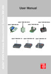
Application example wireless measurement system
base module
USB, RS232
LAN or
WLAN
PC
repeater module
(optional)
sensor modules
temperature sensor
grain
Fig. Storehouse for grain
8
grain
grain
Product description
The temperature monitoring in storehouses for grain is mostly still done manually,
this means that every measuring point is controlled by an employee at least once a
day. This procedure is very cost and time consuming.
The solution is the wireless measurement system. Every measuring point can be
equipped with up to six temperature measuring sensors. So it can be used area-wide
in storehouses for grain, storehouses for bulk goods or similar warehouses. Depending on the measuring interval, a total of up to several hundred measuring points is
possible. In order to be able to achieve a sufficient radio coverage or higher ranges,
repeaters can be used. They extend the operational range of the wireless measurement system by far.
Modules of the wireless measurement system
Base module
The base module receives the transmitted data of the sensor modules and transfers
these over a RS232, USB, LAN or WLAN interface to a PC or an IP network.
The RS232 interface is available at all module versions.
The LAN or WLAN interfaces make the connection to an Intranet or to the Internet
possible and therewith the worldwide inquiry of the measurement data.
At the combination LAN / RS232 (alpha WSN BM 110), the voltage supply will be
realized over an external pluggable power supply unit or over the LAN connection
(PoE – Power over Ethernet) if an appropriate PoE voltage supply is installed in the
LAN.
At the combination USB / RS232 (alpha WSN BM 120), it is possible to realize the
voltage supply over the USB interface. Alternatively, the voltage supply can also be
realized over a power supply unit.
At the combination WLAN / RS232 (alpha WSN BM 130), the voltage supply has to be
realized over an external power supply unit.
Sensor module
The sensor module is for the connection of different sensors.
The acquired data is transmitted to the base module by radio and from there, they
are transferred to a PC.
An inquiry as well as setting of the parameters of the sensor modules from base
module (polling) is also possible.
The voltage supply is realised over an internal 3.6 V battery (lithiumthionylchloride,
size 2/3 A). In case the battery voltage is falling below the minimum battery voltage, a message is sent to the base station. The battery should be changed then. An
intelligent power management guarantees a long battery lifetime up to several years
(depending on the size of the network, the propagation conditions and the measuring
interval).
9
Description of device-specific features
Repeater module
The repeater module is for the transmission of the sensor data to the base module. It is
used in case of difficult radio propagation conditions or in case the distances between
sensor and base module are too great.
The voltage supply is realized via an external power supply unit.
A voltage supply over an internal 3.6 V battery (lithiumthionylchloride, size LR14) is
possible, but it is not recommended because of the higher power demand of the
repeater module.
Description of device-specific features
Base modules
The base modules of the wireless measurement system are the interface to the PC world
or an IP network. They receive the data of the single sensor modules and transfer them
to a PC. Connections over RS232, USB, LAN or WLAN are available for this.
The base module can temporarily store up to approx. 45,000 sensor data sets. In case
of a temporary termination of the visualization software or switching off of the PC, the
sensor data is so buffered and is not lost.
After starting the visualization software again, the data is transmitted to the PC.
Furthermore, the base module is equipped with two potential-free outputs (change-over
contacts) that can be controlled from the PC, if required (alarm signalling).
There are two LEDs at every base module. The green LED indicates the operation of
the module (glowing when the module is active) and the red LED indicates correctly
transmitted and received packets of data.
Status LED (red) glowing for approx. 50 ms:
Status LED (red) glowing for approx. 500 ms:
10
packet of data transmitted correctly
packet of data received correctly
Description of device-specific features
Functional elements and interfaces
��������������
�����
���
�������������
Fig.: Functional elements BM 110, BM 120, BM 130
All base modules have a standardised socket board with potential-free outputs.
These can e. g. be used as alarm outputs. The control is realized over the visualization software alpha data view. This interprets the received data and sends a command for the activation of the alarm outputs to the base module, if required. Following, the Pin assignment of the socket board is described.
Pin
1
2
3
4
5
6
Designation
K1-C 2
K1-C 1
K1-C 3
K1-B 3
K1-B 1
K1-B 2
Function
relay switch 2 normally closed contact
relay switch 2 central contact
relay switch 2 normally open contact
relay switch 1 normally open contact
relay switch 1 central contact
relay switch 1 normally closed contact
Table: Pin assignment of the socket board at all base modules
Designation
Interior contact
External contact
Function
signal
ground
Table: Assignment of the antenna socket
Colour
red
green
Function
status
operation
Table: Assignment of the LEDs
11
Description of device-specific features
Base module with LAN interfaces alpha WSN BM 110
����������������������������
����������
������������
Fig.: Functional elements BM 110
Pin
1
2
3
4
5
6
7
8
9
Designation
N.C.
RXD
TXD
N.C.
GND
N.C.
N.C.
N.C.
N.C.
Function
not connected
received data
transmission data
not connected
ground
not connected
not connected
not connected
not connected
Table: Pin assignment of the RS232 socket
Pin
1
2
3
4
5
6
7
8
Designation
Tx+
TxRx+
Rx-
Function
transmission data
transmission data
received data
PoE 1
PoE 1
received data
PoE 2
PoE 2
Table: Pin assignment LAN socket
Designation
Interior contact
External contact
Function
positive supply voltage
ground
Table: Assignment of the power supply unit socket
12
Description of device-specific features
Base module with USB interfaces alpha WSN BM 120
������������
����������������������������
����������
Fig.: Functional elements BM 120
Pin
1
2
3
4
5
6
7
8
9
Designation
N.C.
RXD
TXD
N.C.
GND
N.C.
N.C.
N.C.
N.C.
Function
not connected
received data
transmission data
not connected
ground
not connected
not connected
not connected
not connected
Table: Pin assignment of the RS232 socket
Pin
1
2
3
4
Designation
VCC
DD+
GND
Function
+5 V supply voltage
data
data
ground
Table: Pin assignment USB socket
Designation
Interior contact
External contact
Function
positive supply voltage
ground
Table: Assignment of the power supply unit socket
13
Description of device-specific features
Base module with WLAN interfaces alpha WSN BM 130
����������������������������
�����������
������������
Fig.: Functional elements BM 130
Pin
1
2
3
4
5
6
7
8
9
Designation
DCD
RXD
TXD
DTR
GND
DSR
RTS
CTS
N.C.
Function
received signal detected
received data
transmission data
terminal ready
ground
readiness for operation
activate transmit unit
ready to send
not connected
Table: Pin assignment of the RS232 socket
Designation
Interior contact
External contact
Function
signal
ground
Table: Assignment WLAN-antenna socket
Designation
Interior contact
External contact
Function
positive supply voltage
ground
Table: Assignment of the power supply unit socket
14
Description of device-specific features
Sensor module
Up to six PT1000 measuring sensors 2-wire technology can be connected to the sensor
module.
By using PT1000 measuring sensors, errors because of line length and temperature
coefficients of the cable from the measuring sensor to the sensor hardly have an effect
on the measuring result.
The automatic length correction makes the connection of cables with a resistance of up to
2.8 Ohm for go-and-return line possible. It is important that all cables have the same
cross section and the same length and that they are connected as described in the
following paragraphs.
The sensor modules have a switching off function that is controllable over the sensor
interface. So it is made sure that the sensor module only transmits data by radio in
case sensors are connected. Two switching contacts are available which have to be
connected to switch on the sensor module. This can be done by means of a switch or
also by means of a solder bridge in the plug.
The sensor module alpha WSN SM 240ex is available in an IP65 housing (explosionprotection zone 21), the sensor module alpha WSN SM 240-G is available in an IP65
housing, the sensor module alpha WSN SM 240 is available as pcb version.
The user can determine the measuring interval of every single sensor module in the
range of 10 s…1 year. The respective sensor module always sends latest measured
values after expiration of this time (also see chapter "Control software and software
interface").
Furthermore, maximum / minimum capacities can be set for every measuring sensor of
every sensor module. The sensor module only transmits valid measuring values when
these are within this range. In case a value outside of this range is measured, an invalid
measured value (0x0000) is sent, the same applies to sensors that are connected wrongly
or defective sensors. See also chapter "Operating software and software interface”.
Versions
The sensor module of the wireless measurement system is available in three versions:
• alpha WSN SM 240ex à for operation in explosion-endangered areas
• alpha WSN SM 240
à pcb version of the sensor module for universal use
• alpha WSN SM 240-G à housing version of the alpha WSN SM 240, but not
for the operation in explosion-endangered areas
The modules alpha WSN SM 240ex and alpha WSN SM 240 are described in detail in
this user manual. The housing version alpha WSN SM 240-G is not described further.
Technically, it corresponds to the sensor module alpha WSN SM 240ex, but it is not
suitable for the operation in explosion-endangered areas!
15
Description of device-specific features
Functional elements and interfaces
alpha WSN SM 240ex / alpha WSN SM 240-G
��������������
�
�
�
�
�
�
�
�
�
�
�
�
�������������������������������
����������������
Fig.: Functional elements SM 240ex, SM 240-G
Designation
F
E
D
K
L
C
A
B
J
H
M
G
Function
on / off contact 1
on / off contact 2
PT1000 measuring sensor 1
PT1000 measuring sensor 2
PT1000 measuring sensor 3
PT1000 measuring sensor 4
PT1000 measuring sensor 5
PT1000 measuring sensor 6
Ground for all measuring sensors
Coding input 1 for line length correction
Coding input 2 for line length correction
Coding input 3 for line length correction
Table: Assignment sensor interface
Designation
Interior contact
External contact
Function
signal
ground
Table: Assignment of the antenna socket
16
Description of device-specific features
alpha WSN SM 240
���������������������
����������������
�����������
�����������
�
�
��������������
��������������
�������������������
Fig.: Functional elements SM 240
Designation
F
E
D
K
L
C
A
B
J
H
M
G
Function
on / off contact 1
on / off contact 2
PT1000 measuring sensor 1
PT1000 measuring sensor 2
PT1000 measuring sensor 3
PT1000 measuring sensor 4
PT1000 measuring sensor 5
PT1000 measuring sensor 6
Ground for all measuring sensors
Coding input 1 for line length correction
Coding input 2 for line length correction
Coding input 3 for line length correction
Table: Assignment sensor interface
Designation
Interior contact
External contact
Function
signal
ground
Table: Assignment of the antenna socket
Designation
+
-
Function
positive supply socket
ground
Table: Assignment power supply socket
17
Description of device-specific features
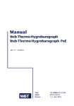
Connection of the sensors
The interfaces described in the previous paragraphs are available for the connection of the sensors. At the sensor module alpha WSN SM240ex, this is the 12-pole
connector at the outside of the housing, at the alpha WSN SM 240, it is the connector
on the pcb. The pins E and F are the two switching contacts. These have to be
connected in order to activate the sensor module.
The connection J is the common mass connection for all PT1000 measuring sensors.
In order to achieve a high accuracy, all return conductors of the measuring sensors
should only be brought together at this point.
Basically, it is also possible to use a very low-resistance return conductor and to
bring the ground of the measuring sensors together elsewhere.
At the coding inputs H, M and G, the length of the cable and its resistance is compensated by means of bridges. Over the specific resistance, the length and the
cross section of the wires to the measuring sensors, the resistance to be set can be
calculated as follows:
R
R
ρ
l
A
=
=
=
=
=
ρ*l/A = 0017Ω*mm2/m *l/A (for copper)
resistance in Ω
specific electrical resistance in Ω*mm2/m
length of the cable in m (add go-and-return line)
cross section of the wires to the measuring sensors in mm2
Resistance in Ω
(go-and return conductor)
0.0 Ω ... 0.2 Ω
0.2 Ω ... 0.6 Ω
0.6 Ω ... 1.0 Ω
1.0 Ω ... 1.4 Ω
1.4 Ω ... 1.8 Ω
1.8 Ω ... 2.2 Ω
2.2 Ω ... 2.6 Ω
2.6 Ω ... 3.0 Ω
Coding input 3
G
Coding input 2
M
Coding input 1
H
0
0
0
0
1
1
1
1
0
0
1
1
0
0
1
1
0
1
0
1
0
1
0
1
Table: Coding line resistance
All coding inputs are automatically set to "1". In order to create a "0" at a coding input,
this has to be connected with the connection F in the plug by means of a bridge.
Example:
Cable length = 10 m (go-and-return line = 20 m), copper
Cross section = 0.14 mm2
R = 0.017*20 m / 0.14 mm2
R = 2.43 Ω (is between 2.2 Ω ... 2.6 Ω )
According to the table, the conding input 1 (H) has to be set to 0, this means be bridged
with connection F. G and M are not connected.
In this way, measuring sensors with a cable lengths of up to 12 m at
0.14 mm2 and 19 m at 0.22 mm2 cross section can be used.
18
Description of device-specific features
F
E
D
K
L
C
A
B
J
H
M
G
switch or bridge
PT1000
1
2
3
4
5
6
connection in plug
Example for the connection of 6 measuring sensors PT1000 at a cable length of 10 m
(go-and-return line 20 m) with copper wire 0.14 mm² cross section.
19
Description of device-specific features
Accuracy alpha WSN SM240ex, alpha WSN SM240 at properly connected
measuring sensors
The sensor modules are a compromise of efficiency and accuracy. In order to be
able to connect as much sensors as possible at the compactness of the module as
well as of the connectors, only a 2-wire wiring was chosen as type of connection. In
order to achieve a high accuracy nevertheless, a line compensation is effected in the
sensor module. Thus, the disadvantages of the 2-wire wiring (resistance of the cable
is regarded as measuring error) can be eliminated to a large extend, particularly also
in case of large line lengths.
alpha WSN SM 240ex or
alpha WSN SM 240 at:
Normal temperature
(15 °C to +35 °C)
Extreme temperature
(-25 °C to +75 °C)
Unit without measuring
sensor
Unit with measuring sensor,
12 m 0.14 mm2 cable,
PT1000 1/3B
Typ.
Max.
Typ.
Max.
+/- 0.3 °C
+/- 0.5 °C
+/- 1.0 °C
+/- 1.5 °C
+/- 0.6 °C
+/- 1.0 °C
+/- 1.5 °C
+/- 2.0 °C
Table: Overview measurement accuracy
Every 5 years, the sensors SM 240ex and SM 240 should be calibrated anew.
Repeater module
The repeater module has the function to transfer the data within the network. In case
a sensor module is too far away from a base module to reach it directly, the range
can be raised by using a repeater. Thereby, it is possible to set up spatially longrange networks by means of sensor modules with low transmitting power. This raises
the energy efficiency and therewith considerably raises the lifetime of the battery.
The repeater modules have to send more often than sensor modules and have
to be ready to receive all the time since they possibly transmit packets of data of
several sensor modules. They are as a rule firmly installed at topological favourable
points and are fed by a power supply unit. In case of need, battery operation is also
possible over a short period of time.
The repeater module alpha WSN RM 300ex is available in an IP65 housing (explosion
protection zone 21), the repeater module alpha WSN RM 300-G is available in an IP65
housing, the repeater module alpha WSN RM 300 is available as pcb version.
The repeater alpha WSN RM 300ex may only be operated in connectin with the approved
barrier MTL7715+ and the required, shielded cable in the explosion-endangered area.
When powering the alpha WSN RM 300 by means of a power supply unit, you have to
make sure that no battery is inserted in the unit.
At the consturction of the network, you have to make sure that the number of repeaters
in the network is kept low in order not to excessively stress the network because of
multiple packet forwardings.
When setting up the network, you have to mind that the number of repeaters in the
network is kept low in order not to stress the network excessively by manifold packet
forwarding.
20
Description of device-specific features
Repeaters should also be installed in places with good radio propagation conditions
(e. g. isolated, elevated mounting places). This raises the range and the quality of the
whole network.
Versions
The repeater module of the wireless measurement system is available in three
versions:
• alpha WSN RM 300ex
à for the operation in explosion-endangered areas
• alpha WSN RM 300
à pcb version of the repeater module for universal use
• alpha WSN RM 300-G
à housing version of the RM 300, but not for use in
operation in explosion-endangered areas
The modules alpha WSN RM 300ex and alpha WSN RM 300 are described in detail in
this user manual. The housing version alpha WSN RM 300-G is not specified. Technically,
the housing version corresponds to the repeater module alpha WSN RM 300ex, but it
is not suitable for the operation in explosion-endangered areas!
Keep in mind that you do not have to use a barrier for the connection of the repeater module
alpha WSN RM 300-G. A universal power supply unit with the required parameters can
be used.
Functional elements and interfaces
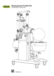
alpha WSN RM 300ex / alpha WSN RM 300-G
voltage supply socket
antenna socket
repeater module
+
power supply unit with battery
cable entry
screw terminal
for earth cable
Fig.: Total view repeater with power supply unit and barrier
Designation
Interior contact
External contact
Function
signal
ground
Table: Assignment of the antenna socket
21
Description of device-specific features
Designation
+
-
Function
positive supply socket
ground
Table: Assignment of the voltage supply socket
alpha WSN RM 300
���������������������
�
�
��������������
Fig.: Functional elements RM 300
Designation
Interior contact
External contact
Function
signal
ground
Table: Assignment of the antenna socket
Designation
+
-
Function
positive supply socket
ground
Table: Assignment voltage supply socket
22
Description of device-specific features
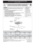
Connection of the barrier (only alpha WSN RM 300ex)
The barrier 7715+ of the company MTL makes sure that no dangers because of defects
(e. g. of the power supply unit) pass into the explosion-endangered area.
You have to make sure that the barrier in the secure area, this means outside of the
explosion-endangered zone, is connected properly and is also earthed.
As power supply unit, only stabilized types with a fixed output voltage (DC) of 12 V
(+/-5 %) and at least 100 mA may be used.
explosion-endangered area
safe area
MTL7715+
RM 300ex
power supply unit DC
12 V stable
Wiring of the barrier MTL7715+ with power supply unit and repeater
The barrier MTL7715+ has four connections (see fig.) and is suitable for top hat rail
mounting.
It is approved for the temperature range from –20 °C up to +60 °C and may only be
operated in this area.
3
HAZ
4
1
SAFE
2
TERMINAL 1: +12 V power supply unit (safe area)
TERMINAL 2: 0 V power supply unit (safe area)
TERMINAL 3: + RM 300ex
TERMINAL 4: 0 V RM 300ex
Fig.: Circuit diagram barrier MTL7715+
23
Description of device-specific features
It is absolutely necessary that the barrier MTL7715+ is earthed according to the
instructions. The earth cable 4 mm2 (12 AWG) is connected to the screw terminal at the
housing of the power supply unit.
The maximum earth resistance and the instructions have to be taken from the description of the barrier.
Only the approved type of cable (Lapp Öflfex EBCY) with a max. length of 20 m may be
connected to the connections 3 and 4 of the barrier. This cable with the type of protection instrinsic safety "i" is especially suitable for the use in explosion-endangered areas.
The shielding of this cable is connected with the screw terminal below the connections
3 and 4.
At the side of the repeater, the shielding stays open which means that it is electrically not
connected with the repeater.
The wire 1 that is connected to terminal 3 of the barrier is connected with the positive
terminal of the voltage supply socket of the repeater. The wire 2 that is connected to
terminal 4 of the barrier is connected with the negative terminal of the voltage supply
socket of the repeater.
voltage supply socket
+ from barrier / wire 1
+
- from barrier / wire 2
Fig.: Connection barrier MTL7715+
The provided cable Lapp Ölflex EBCY is suitable for flexible applications at free motion
without tensile load and without compulsory motion control as well as for fixed laying
in dry, damp and wet rooms, but it is not suitable for outdoor use.
In case a laying of the cables in the outdoor area should be necessary, it is recommended to use a protective tube.
In case of fixed laying, the cable may be used in the temperature range from -30 °C
up to +80 °C, otherwise it is approved for the temperature range from -5 °C to +70 °C.
24
Putting into operation
Putting the units into operation
Delivery status
The RS232 interface of the base modules and the virtual COM-Port of the base
module alpha BM 120 (USB-Port) are set to the parameters 115.200 baud, 8 data
bits, no parity bit, 1 stop bit.
The setting of the virtual COM-Ports at the base module alpha BM 110 and
alpha BM 130 is carried out similar to this.
The measuring interval of the sensor module is set to 8 hours.
The measuring range of the sensors is set to the range -40 °C ... 110 °C.
Initial state of the base module after connecting
All base modules can be connected to a PC by means of a serial cable.
An external voltage source is required for the power supply. For this, the base
modules are equipped with a socket for the connection of an external power supply
unit. After connecting the power supply unit to the RS232 cable, the base module
automatically switches to receive mode.
Base module alpha WSN BM 110
In case the base module is connected to a PC over a LAN connection, an external
voltage source has to be used for the power supply. For this, the base module is
equipped with a socket for the connection of an external power supply unit.
An exception is the possibility of voltage supply over the LAN connection, in case the
LAN is equipped with an appropriate voltage source 802.3af mid span power passthrough (PoE=Power over Ethernet). After connecting the power supply unit and a
LAN cable or only a LAN cable in case of PoE feeding, the base module automatically switches to receive mode. In case of voltage supply of the LAN module over
Ethernet, the power supply unit should be separated from the unit.
Base module alpha WSN BM 120
In case the base module is connected to a PC by means of an USB cable, no external power supply unit is necessary. The base module is automatically energised
over the USB port. After connecting the USB cable, the base module automatically
switches to receive mode. In case the base module is connected with a PC over
USB, no power supply unit should be connected.
Base module alpha WSN BM 130
In case the base module is connected to a PC over a WLAN connection, an external voltage source has to be used for the power supply. For this, the base module
is equipped with a socket for the connection of an external power supply unit. After
connecting the power supply unit, the base module automatically switches to receive
mode.
25
Putting into operation
Initial state of the sensor module after starting
Insert the battery according to the polarity at the sensor module.
Please note: Wrong polarity can lead to the destruction of the unit!
After inserting the battery into a sensor module and connecting the sensor plug, this
sensor module independently starts to send its measurement data to the base station
in a preset interval.
Initial state of the repeater module after starting
After connecting the power supply unit or after inserting the battery, the repeater
module automatically switches to receive mode and forwards the received data.
Please note: Wrong polarity can lead to the destruction of the unit!
Please note:
Connect the cable of the power supply unit with the correct polarity!
Mounting
General instructions
Please read the chapter "Antennas" before mounting the units to
walls, ceilings or into housings!
Mounting instructions for the base module alpha WSN BM 1x0
The base module has to be operated in the indoor area. You just have to mind good
propagation conditions, this means that the antenna should not be restricted in receiving in the direction of the sensors. The base module should not be covered and not
be exposed to direct sunlight.
Mounting instructions for the sensor module alpha WSN SM 240ex
The sensor module may only be operated in the marked protection zones. For
mounting, only use the supplied mounting material. The mounting has to be carried
out that way that the housing of the sensor module is in no case opened within the
explosion-endangered area. All maintenance (e. g. changing of batteries) may only
be carried out outside of the explosion-endangered area! Do not operate the sensor
module without antenna!
26
Putting into operation
Mounting instructions for the repeater module alpha WSN RM 300ex
The repeater module may only be operated in the marked protection zones. For
mounting, only use the supplied mounting material. The mounting has to be carried
out that way that the housing of the repeater module is in no case opened within the
explosion-endangered area. All maintenance (e. g. changing of batteries, connection
of the barrier) may only be carried out outside of the explosion-endangered area! Do
not operate the repeater module without antennas!
Mind the correct installation of the barrier! You will find a detailed description in the
chapter "Connection of the barrier".
Instructions for the operation of the PCB version (alpha WSN SM 230,
alpha WSN RM 300)
When operating the PCB version with the provided standard antennas, you have to
mind that the antennas need a counterpoise. This means that the antenna has to be
mounted on a conductive base that needs a conductive connection to the ground.
This base should have the shape of a cross (length of every leg approx. 15 cm) and
the antenna should be mounted in the middle. But you can also use a full surface of
the same size.
In case the base is reduced, you will have to expect a deterioration of the propagation conditions. By this, the efficiency of the wireless measurement system, especially
the efficiency of the range, is restricted.
Furthermore, you should bear in mind that, especially at operation with the power
supply unit with voltages higher than 15 V, there has to be sufficient circulation of air
and there may be no extremely high temperatures at the place of installation.
Please note:
The following applies to all units alpha WSN SM 230 and alpha WSN RM 300:
During operation with the power supply unit, no battery may be inserted into the
unit!
27
Putting into operation
Configuration of the interfaces
Setting the RS232 interface or settings at the terminal programme
In case your computer has a free COM-Port (9-pole), you can use this connection
for the connection with the base module. Then it will not be necessary to install
additional drivers.
The parametrisation can be done with any terminal programme.
The manufacturer recommends to use the programme Hyperterminal from
Microsoft Windows.
���
����������������������������������
�����
��������������������������
�����������������������������
�������������������������������������
��������������������������������������
�����������������������������
���
28
��������������������������������
�����������������������
��������������������������
�����������
Putting into operation
���
���������������������������������
������������������������������������������������
�������������������������������������������
������������������
�����������������������������
����������������������� ����������������
���������������������������������������������
���
���������������������
�����������������������������������
����������������
���
��������������������������������
�����������������������������������
�����������������������
�����������������������
29
Putting into operation
���
����������������������������������
��������������������������������
��������������������
���������������
������������������������������
������������������������������������
���������������������
��������������������������������
��������������������������
���������������������������
���
��������������
����������������������
�����������������������������
���������������������������������
���������������������������������
���������
����������������������������������
����������������������������������
������������������������������������
������������������������������������
������������������������������������
������������������������������
After confirming the options, the terminal programme is ready to send and to receive.
When using another terminal programme, the settings have to be carried out like
explained in the example of the Hyperterminal programme.
30
Putting into operation
Setting the USB interface
In case your PC is equipped with an USB interface, you can use this connection for
the connection with the base module alpha WSN BM 120. For this, you have to have
administrator rights or you have to be logged in as system administrator at the system. Install the supplied USB driver as described following.
Automatic USB driver installation
1. Connect the base module alpha WSN BM 120 with the computer by means of an
USB cable. A message about newly found hardware is displayed. If this is not the
case, please read the chapter "Manual USB driver installation".
Fig.: New hardware found
2. Click on "Weiter" (Next) in the next window.
Fig.: Assistant for searching new hardware
31
Putting into operation
3. Click on "Weiter" (Next) in the next window.
Fig.: Assistant for searching new hardware, install driver
4. Click on "Weiter" (Next) in the next window.
Fig.: Select driver source
The driver is now searched on the supplied CD and installed.
32
Putting into operation
5. Click on "Weiter" (Next) in the next window.
Fig.: Driver files found
6. Click on "Fertig stellen" (Finish) in the next window.
Fig.: Finish driver installation
With this step, the driver installation is finished.
33
Putting into operation
Manual USB driver installation
In case you see the following symbol down right in the corner of the screen after
connecting the base module alpha WSN BM 120 and the dialogue for installing
the USB driver does not appear, the USB hardware of the base was not detected
automatically.
Fig.: USB hardware that was not detected
You can install the required driver manually with the following steps:
1. Open the device manager with:
START à Einstellungen à Systemsteuerung à System à Hardware à
Geräte-Manager.
Fig.: Open device manager
34
Putting into operation
2. Open the properties dialogue of the unit "CP2101 USB to UART Bridge Controller" by a double-click. This is marked by a yellow exclamation mark.
Fig.: Open properties dialogue
3. Click on "Treiber erneut installieren…" (Install driver again...) in the properties
dialogue.
Fig.: Properties dialogue, install driver again
35
Putting into operation
4. Click on "Weiter" (Next) in the following window.
Fig.: Assistant for updating device drivers
5. Click on "Weiter" (Next) in the following window.
Fig.: Assistant for searching new drivers
36
Putting into operation
6. Insert the supplied CD into the CD-ROM drive.
Select "CD-ROM-Laufwerke" (CD-ROM drives) as source for the driver search.
Click on "Weiter" (Next).
Fig.: Select the source for the driver
7. Finish the installation with "Fertigstellen" (Finish).
Fig.: Finish the manual driver installation
If you can still see a yellow exclamation mark in the device manager, please carry out
the instructions of this chapter a second time.
37
Putting into operation
Checking the USB driver settings
To check the correct installation of the USB driver, please proceed as follows and
open:
1. Start à Einstellungen à Systemsteuerung à System à Hardware à
Gerätemanager
2. Click on the "+" in front of "Anschlüsse (COM und LPT)" (Connections (COM and
LPT))
Fig.: Device manager
3. Twice click on the entry: "CP2101 USB to UART Bridge Controller (COMx)".
A new COM-Port (COMx) should be entered here now. The "x" stands for the
respective COM-Port that has to be set, e. g. COM2.
4. Then select the button "Anschlusseinstellungen".
5. Check the following settings:
bits per second:
115200
data bits:
8
parity:
none
stop bits:
1
flow control:
none
6. Close the window and terminate the device manager.
If all installations are correct, a new COM-Port for the communication with the base
module is available now.
38
Putting into operation
Link test USB-Port
Open a terminal programme (e. g. Hyperterminal from Microsoft Windows) and install
it according to chapter "Settings at the RS232 interface" or "Settings at the terminal
programme".
Open the COM-Port you have just installed and send a <CR> (Carriage Return) to
the base module. If everything is set correctly, you should see a message of type
0x72 of the base module in the terminal window. Also see chapter "Protocol description". If this is not the case, it will not be possible to communicate correctly with the
base module. Please have a look at the chapter "Troubleshooting" for this topic.
Setting the LAN interface
In case your PC is equipped with a LAN interface, you can use this connection for the
connection with the base module alpha WSN BM 110. For this, you have to have
administrator rights or you have to login to the system as system administrator. Install
the supplied LAN driver as described following.
When connecting a base module alpha WSN BM110 over a LAN cable directly to a
PC (no PC network), a crossed Twisted Pair LAN cable has to be used.
A HTML page is available for all manual configurations. In order to be able to make
changes, start a browser (e. g. Internet Explorer) and enter the IP address of the LAN
module into the address line. In case you do not know the IP address, have a look at
the chapter "Searching for modules by means of Discovery-Tool".
Fig.: Configuration page LAN modul
Automatic setting of the IP address
The LAN module of the base module alpha WSN BM 110 is set to DHCP by default.
So the IP address will automatically be assigned in case a DHCP server exists.
39
Putting into operation
Manual setting of the IP address
In case no DHCP server is available, the IP address can also be configured manually.
Proceed as follows:
Open a browser (e. g. Internet Explorer) and enter the current IP address of the
LAN module into the address line. As a result, the configuration page will be opened.
Fig.: Configuration page network settings
Setting Serial-Port-Profile
So that the base module of the wireless measurement system works best possible, it
is necessary to configurate the Serial-Port-Profile of the WLAN module correctly. For
this purpose, select the point "Serial Port" on the configuration page under "Configuration" and set the Radio Button to "RealPort".
Fig.: Configuration page Serial-Port-Profile
40
Putting into operation
Further settings of the LAN module
The LAN module is by default provided with a configuration that is optimal for many
applications. Should it however become necessary to optimize the configuration, a
multitude of settings can be made manually. A HTML page is available for this purpose. Open a browser (e. g. Internet Explorer from Microsoft) and call the configuration page (by entering the IP address into the address line).
Setting the WLAN interface
The base module alpha WSN BM 130 provides the opportunity to make the received
data available over a WLAN. The PC, on which the data shall be displayed, has to be
equipped with WLAN or with a LAN port for the connection of a WLAN access point
as well as with an Internet browser.
A HTML page is available for all manual configurations. In order to be able to make
changes, start a browser (e. g. Internet Explorer) and enter the IP address of the LAN
module into the address line. In case you do not know the IP address, have a look at
the chapter "Searching for modules by means of Discovery-Tool".
Fig.: Configuration page WLAN module
Automatic setting of the IP address
The WLAN module of the base module alpha WSN BM 130 is set to DHCP by default.
So the IP address will automatically be assigned in case a DHCP server exists.
41
Putting into operation
Manual setting of the IP address
In case no DHCP server is available, the IP address can also be configured manually.
Proceed as follows:
Open a browser (e. g. Internet Explorer) and enter the current IP address of the
WLAN module into the address line. As a result, the configuration page will be
opened.
Fig.: Configuration page WLAN module
Setting Serial-Port-Profile
So that the base module of the wireless measurement system works best possible,
it is necessary to configure the Serial-Port-Profile of the WLAN module correctly. For
this purpose, select the point "Serial Port" on the configuration page under "Configuration" and set the Radio Button to "RealPort".
Fig.: Configuration page Serial-Port-Profile
42
Putting into operation
Setting the encoding
If you want to use an encoded radio transmission, the encoding will have to be activated. Proceed like at the manual setting of the IP address. But then select "Wireless
Security Settings" on the page "Network Configuration". Now you can carry out the
desired security settings.
Fig.: Configuration page WLAN security settings
Further settings of the WLAN module
The WLAN module is by default provided with a configuration that is optimal for many
applications. Should it however become necessary to optimize the configuration,
a multitude of settings can be made manually. A HTML page is available for this
purpose. Open a browser (e. g. Internet Explorer from Microsoft) and call the
configuration page (by entering the IP address into the address line).
Searching for modules by means of Discovery-Tool
In case you do not know the address of a LAN module and/ or you do not have a
DHCP server, modules that are not obtainable can be found by means of the
Digi-Device-Discovery-Tool and the IP address can be configured.
The Device-Discovery-Tool can be downloaded on the following website:
http://www.digi.com/support/productdetl.jsp?pid=2466&osvid=56&s=53#utilities.
After starting the programme, all obtainable modules are automatically searched and
displayed. If you click on the desired module and afterwards on the link "Configure
network settings", you will get to the setting page for the network parameters.
43
Putting into operation
The module can be configured to DHCP or a fixed IP address there.
Fig.: Main window of the Discovery-Tools
Fig.: Network settings
44
Operation
Control software and software interface
Control software alpha data view
For the operation of the wireless measurement system, an easily operated Windows
software is available. By means of this software, the measured values of the sensors
existing in the network can be represented and stored. Measuring interval and range
limits can also be set.
Installation of the control software alpha data view
For the installation, insert the supplied CD into the CD-ROM drive of your PC and
follow the instructions on the screen. In case the autostart function should be deactivated, please start the file SETUP.EXE.
Short description of the control software alpha data view
Before starting the programme, please inform yourself about the connections (COM
and LPT) that you want to use for the communication with the connected base station
in the device manager of your operating system (see chapter "Configuration of the
interfaces").
1. Start programme alpha data view
2. Open the interface to the base station (menu item settings)
3. Leave the display window base station (button: close window)
The surface of the programme is divided into three windows that are adjustable
in size. These windows are referred to as follows: table window (left), main
window (top right) and event window (down right). In the main window of the
programme, a two-dimensional matrix display of the sensors appears.
4. Putting the sensor modules into operation
The sensor modules log on to the base station an. These are shown in the
table window as address number.
5. Assign the address numbers to the matrix
5.1 Move the mouse pointer to a sensor of the matrix display
5.2 Press right mouse button
5.3 Select menu item "Adresse eingeben" (Enter address)
5.4 Enter address and press button "Übernehmen" (Accept)
6. Repeat the points 4 and 5 for all sensors of the wireless network
7. Chart the sensor data (diagram display)
7.1 Move the mouse pointer to a sensor of the matrix display
7.2 Press left mouse button
8. Define the colour of the line
8.1 Actuate keys measuring point 1 ... 6
8.2 Set the colour of the line for the selected measuring point
45
Operation
Setting the sensor parameters
You can set the sensor measuring interval and the range limits (min-temperature
value, max-temperature value) at all wireless sensor modules that are registered at
the base station and entered in the matrix.
1. Select diagram display of a wireless sensor module
2. Actuate button "Sensoreinstellungen" (Sensor settings)
3. Enter parameter values
4.
46
Actuate button "Werte übernehmen" (Accept values)
Operation
Selecting alarm criteria for all sensors
1.
2.
Select alarm settings (menu item settings)
Enter parameter values
3.
Confirm OK button
47
Operation
Software interface
For users who want to develop an own application for the wireless measurement
system, a software interface for the operation of the system is available. By means
of this interface, you can access the same functionality like that one that is available
to the control software. Following, the messages between PC and base module are
explained.
Protocol description
Basically, it is distinguished between two message types.
1. Messages from the base module to the PC
2. Messages from the PC to the base module
Following, both types are explained in detail.
Messages from the base module to the PC
!"
"#$%
"&
!"$
!"
"#$%
"&
!"
"#$%
"&
!"
"#$%
"& 2
+
3))"$%
"&
5
6)"&."&
*
0&
#
7
$%"&
#
7
$%"&
#
:
"
0&
#
"; 7
$%"&
#
"; 7
$%"&
#
:
6<
4=4
6<
?.
4&=
)
()*+,
$-.$/ 0!
7
7
7
7
7
7
7
7
7
4=4
4=4
4$
)$)3))"
$""$889
4/)"$8
>>6<
7
'
1
Table: Message base module à PC
The data area is max. 34 byte at messages over radio interface and max. 47 byte at
messages of the base module only over UART.
48
Operation
Messages from the PC to the base module
'
-
/
0
$
$1
$1
0
"2
"2
!
"#$%&$%
(%
)
.$%
)
.$%
)
(%
)
.$%
)
.$%
)
343
7&
3%4
#
343
343
*$$++,
35#$+
66"2
Table: Message PC à base module
The data area is max. 31 byte.
49
50
�������������������������������������������������
�����������������������������������
�������������������������������������
�����������
�������������������������
������������������������������������������������
������������������������������������������
��������������������������������������
������������������������������������
������������������������������
�����������������������������������
���������������������������������
���������������������������
���������������������������������
�������������������������������
������������������������
��������������������������������
������������������������������
�����������������
�������������������������������������
�����������������������������������
����������������������������������������������
��������������������������������������������
�������������������������
������������������������������������
�������������������������
������������������������������������
��������������������������������������
�����������
��������������������������������
����������
�������������������������������
����������������
�������������������������������������
������������������������������������
���������������
�����������
���������������
����������
���������������
�����������
��������������
����������
��������������
����������
���������������
��������������
��
���������������
����������������
���������������
����������
���������������
����������
���������������
����������
���������������
����������
��������������
������
��������������
������
���������������
������
���������������
�����
���������������
��������
���������������
��������
���������������
����������
���������������
���������������
�����
���������������
������������
������������������������
���������������������������
�����������������������������������
������������������
��
��
�����
�����
��
�����
��
���
�����
�����
��
�����
���
�����
��
��
�����
�����
��
�����
��
��
�����
��
�����
�����
��
��
��
�����
�����
���
�����
�����
��
��
��
��
����������
��������������
�����
��
������������
������
�����
�����
�����
�����
��������
��������
������
��������
������
��������
��������
������
��������
��������
��������
�����
��������
������
�����
������
���������
��������
�������
�����
�������
�����
�������
�����
��
�������
�����
��
��
��
������
��
��
��
��
���
����������
���
���
���
���
����
������
����
����
��������������������������������������������������������������������������������
������������������������������������������������
����
�������������������������������������������������������������������������������
�������������������������������������������������
��
���������������
�����������
�����������
��
������
��
����
���
����
���
����
����
���
����
���
����
���
Operation
Overview of commands
������������������������������������������������
����������
�����������������������������������������������
����������
����������������������������������������������
��������������
������������������������������������������������
���������������������������������������������������
��������������������������������������������
��������������������������
�����������������������������
�������������������
��������������������������������������������
������������������������
���������������������������������������
���������������������������
�����������������������������������������
��������������������������������������������
���������������������������������������������
�����������������
����������������������������������
������������������������������������������
���������������������������������������
�����������������������������������
������������������
���������������������������������������
�����
����������������������������������������������
���������������
�������������������������������������������������
�����������������������
��������������������������������������������������
����������������
��
�����������������
��
����������������
��
����������������
����
���������������
������������������
����
�����������������
����
����������������
�����������������
��
�����������������
������
����������������
����������������
��������������
����������������
���������������
�����������������
���������
�����������������
���������
����������������
�����������������
�����
����������������
�������������
��
��
��
��
�����
�����
��
��
�����
�����
��
��
�����
��
�����
��������
��������
��������
��������
��������
��������
��������
��������
��������
��
��
�����
�����
�����
��������
�����
��������
��
��
�����
�����
�����
��������
��������
��
��
�����
�����
����������������������������
�����������������������������
���
���
��������������������������
������
��
�����
���
��
������
��
�����
�����
�����
������
������
��
�����
��������
������
��
��
��
�����
�����
�����������������
��������������
�����������������
�����
�����
��������
��
�����
�����������������
��������������
������
������
��������
��
��
��
��
������������
������
�����
�����
��������
���������
�����������������
����������
�����������������
��
�����������������
����������
�����
�����������������
��
������������
������������������������������������������
�������������������������������
������������������������������������������������
������������������������������������������
�����������������������������
�������������������������������
���������������������������������
�����������
����������������������������
��������������������������������������������������
�����������������������������������������
��������������������������������������
���������������������������������������������������
�������������������������������������
���������������������������������
����������������������������������
�����������
��������������������������������
����������
�������������������������������
����������������������������������������������
������������
����������������������������������
��������������������������������
��
��
��
��
��
���
����������
���
���
���
���
���
���
���
���
���
Operation
Table: Overview of commands
51
Operation
Description data bytes
Sensor type Bit 7
0
1
Sensor type Bit 6..0
0x16
0x17
0x18
0x19
0x1A
0x1B
R
valid
error
channel 1 PT1000
channel 2 PT1000
channel 3 PT1000
channel 4 PT1000
channel 5 PT1000
channel 6 PT1000
Resistance value * 10 for PT1000 channels (0àinvalid value,
e. g. the Min / Max values
State (SENSOR_MSG_RES)
0x07 Type of sensor unknown
0x08 Current module is no sensor module
0x01 Internal error
Sync
0x01 Time transmitted is synchronous
Timestamp
Timestamp à time in s since 1st January. 1970, 0:00 o'clock
State general
0x00 Command executed successfully
0x01 Error during executing the command
Voltage
Voltage in mV
netID
Module network ID
SensorPolling
Sensor sampling interval in s (only sensor module! – otherwise 0)
R
State (SERVICE_MSG_INFO_RES)
Bit0 = 1 Read module configuration OK
Bit1 = 1 Read module configuration OK, only at sensor modules
Bit3 = 1 External reference source available
USB detect (only USB Base); PoE detect (only LAN Base);
Bit4 = 1
power supply unit detect (only Repeater)
HF Transciever standby (higher power consumption, faster
Bit5 = 1
switching times)
ModType
Bit 7 Module group Base
Bit 6 Module group Repeater
Bit 5 Module group Sensor
52
Bedienung
Module type (0=>USB Base; 3=>PT1000 6-channel;
4=>Repeater; 5=>LAN Base; 6=>WLAN Base)
RES
Reserved
State (SERVICE_MSG_PC_LOGIN_RES)
0x00 Base module ready
0x01 Error
Count
Number of buffered messages in the flash
State (SERVICE_MSG_PC_LOGOUT_RES)
0x00 Base module ready, buffer active
0x01 Error, messages can possibly not be buffered
State (SERVICE_MSG_PC_RES)
0x00 Base module ready
0x01 Base module has buffered messages
State (SERVICE_MSG_DATA_FLASH_RES)
0x00 Reading finished
0x01 No reading possible or reading cancelled with error
0x03 Data set with CRC Error, los of file
0x04 Data set with length error, Message inconsistent, loss of data
State (SERVICE_MSG_DEL_DATA_FLASH_RES)
0x00 Deletion finished without error
0x01 Error, Deletion not / uncompleted possible
State (SERVICE_MSG_ALERT_REQ)
0x05 Set alarm output active
0x06 Set alarm output inactive
RSSI (SERVICE_MSG_RSSI_IND)
RSSI Field strength value * 10 dBm (signed)
Bit 3..0
Table: Description data bytes
53
Operation
Setting the measuring interval
���������������������
������
�����
�����
�����
�����
�����
�����
�����
�����
�����
�����
�����
�����
�����
�������������������
�������������������
�����
�����
��������������������������
��������������������������������������������
�����
�����
�����
�����
���������������������������
�����������
����������
����������
����������
����������
����������
����������
��������
���������
�������
��������
����������
Two specific commands are necessary for the setting of the measuring interval. The
first command (message type REQ:0x88 RES:0x08) sets the measuring interval. The
second command (message type REQ:0x8C RES:0x0C) loads the module configuration anew. These commands have to be sent to the base module. The messages as
well as the appropriate answers are given in the following table.
Table: Setting measuring intervals
54
����������������������������
�������
����������������������������
�����������������
����������������������������
�������
����������������������������
�����������������
����������������������������
�������
����������������������������
�����������������
����������������������������
�������
�����������
�����
�����
�����
�����
�����
�����
�����
�����
�����
�����
�����
�����
�����
�����
�����
�����
�����
�����
�����
�����
�������
��������
���
���������
��������
�����
�����
�����
�����
�����
�����
�����
�����
�����
�����
����������
�����
�����
�����
�����
�����
�����
�����
�����
�����
�����
����������
�����
�����
�����
�����
������
�����
�����
�����
�����
������
���������������������
�����
�����
�����
�����
������
���������������������
����������
�����
������������������������������������������
�����
�����
����������
�����
������������������������������������������
�����
�����
����������
���������������������
����������
�����
������������������������������������������
�����
�����
����������
�����
������������������������������������������
���������� ���������� ���������� ����������
Operation
The setting of the range limits is done analogue to the setting of the measuring
interval. The following table shows the necessary messages and answers for every
measuring sensor.
Setting the minimum and maximum capacities
55
56
����������������������������
�������
����������������������������
�����������������
������������������
�����������������
����������������������������
�����������������
����������������������������
�������
����������������������������
�����������������
����������������������������
�������
����������������������������
�����������������
�����������
������
�����
�����
�����
�����
�����
�����
�����
������
�����
�����
�����
�����
�����
�����
�����
�����
�����
�����
�����
������
�����
�����
�����
�����
�����
�����
�����
�����
�����
�����
�����
�����
�����
�����
����������
������������������������������������������������
�����
�����
�����
�����
�����
������
�����
�����
�����
�����
�����
�����
�����
�����
���������������������
�����
�����
�����
�����
�����
�����
�����
�����
����������
������������������������������������������������
���������������������
�����
�����
�����
�����
�����
�����
�����
�����
����������
������������������������������������������������
���������������������
�����
�����
�����
�����
�����
�����
�����
�����
����������
������������������������������������������������
���������������������
�����
�����
�����
�����
�����
�����
����������
�����
����������
����������
����������
����������
����������
����������
��������
���������
�������
���
��������
Operation
����������������������������
�����������������
����������������������������
�������
����������������������������
�����������������
����������������������������
�������
����������������������������
�����������������
����������������������������
�������
����������������������������
�����������������
����������������������������
�������
����������������������������
�����������������
�����������
������
�����
�����
�����
�����
�����
�����
�����
������
�����
�����
�����
�����
�����
�����
�����
�����
�����
�����
�����
������
�����
�����
�����
�����
�����
�����
�����
�����
�����
�����
�����
������
�����
�����
�����
�����
�����
�����
�����
�����
�����
�����
�����
���������������������
������
�����
�����
�����
�����
�����
�����
�����
�����
�����
�����
�����
�����
�����
�����
�����
�����
�����
�����
�����
����������
������������������������������������������������
���������������������
�����
�����
�����
�����
�����
�����
�����
�����
����������
������������������������������������������������
���������������������
�����
�����
�����
�����
�����
�����
�����
�����
����������
�������������������������������������������������
���������������������
�����
�����
�����
�����
�����
�����
�����
�����
����������
������������������������������������������������
���������������������
�����
�����
�����
�����
�����
�����
����������
�����
����������
���������
����������
����������
����������
����������
��������
���������
�������
���
��������
Operation
Table: Setting of range limits
57
Operation
Login procedure PC at the base module
The base module has the possibility to buffer received data sets in case of temporary
switching off of the PC. A registration of the PC at the base module is necessary to
control this mechanism.
After activating the base module, it sends the message "SERVICE_MSG_MODULE_
LOGIN_IND". This has to be acknowledged in every case. For this purpose, the PC
sends the message „SERVICE_MSG_PC_LOGIN_REQ“.
In case the base station has already been activated when the application software
is started, the message "SERVICE_MSG_PC_LOGIN_REQ" will also have to be sent
from the PC. The base module acknowledges the message and gives an information
whether stored data exists. These data can now be recalled and deleted.
After successful login, the base module now outputs all data sets over the interface to
the PC.
The base module waits for a message from the PC for the connection control every
5 minutes during operation. This message should occur at the latest after 5 minutes,
but at the earliest a few seconds before.
In case this message is missing, the base module automatically starts to store the received data sets. In case the connection is established again, the base module then
gives the PC an information that the data was stored.
In case the application software should be closed shortly, the PC releases a logout
message. The base module acknowledges this message and stores the received
data sets from then on until the new login of the PC.
Please bear in mind that only a limited number of data sets can be buffered!
58
Operation
Login procedure
�����
���
�����������
��������������������������
�����������
������������
������������������������
���������
�������������
���������
�������������
�����
������
��������
���������
���
���������
����������
������������
��������������������������
���
��
��
��
�����
������������
��
�������
����������
��������
���
������������������������������
��
����������������
������������������
������������������
�����������
��
����������������
������������������
���
Fig.: Login
59
Operation
���
�����������������������
�
������������
���
���
�
�
������������������������
���������������
��������������������
���������������
�����������������
�������������������
����������
������������������������������
�������������������������
����������������������
�
�
������������������������
�����
��������
���
���
���
���
����������������������������������
�������������������������
������������
�
�
������������������������
���
���
�
�
����������������������������
���������������
��������������������
���������������
������������������
��������������������
������������������������������
������������������������������������
���������������
���������������������������������������������������������������
�������������������
������������
�
�
Fig.: Example Login
60
�������������������
���
���
�
�
����������������������������
���������������
��������������������
����������������
������������������
�������������������
������������������������������
���������������������
Operation
Logout procedure
���
���������
�������������
���������
����������������������
�������
����������������
��������
�������
��������
����
������������
��������
��
����������������
����������������
Fig.: Logout
�������������������������������������
�������������������������
������������
�
�
�������������������������
���
���
�
�
������������������������
���������������
��������������������
����������������
������������������
�������������������
�����������������
Fig.: Example Logout
61
Operation
CRC calculation
A check sum is added to every packet of data. This is a check value with which errors
in the packet of data can be found out.
The basis of the CRC calculation is a table with 256 elements. By means of this table,
the correct check sum is determined for every packet. The receiver controls the
check sum by repeating the calculation for the packet of data and comparing this
value with the transmitted CRC value. In case there are differences, it is assumed that
it is a data error.
Following, you will find the CRC table as well as the function for calculating the check
sum.
unsigned char crc8Table[256] =
{
0, 49, 98, 83, 196, 245, 166, 151, 185, 136, 219, 234, 125, 76, 31, 46,
67, 114, 33, 16, 135, 182, 229, 212, 250, 203, 152, 169, 62, 15, 92, 109,
134, 183, 228, 213, 66, 115, 32, 17, 63, 14, 93, 108, 251, 202, 153, 168,
197, 244, 167, 150, 1, 48, 99, 82, 124, 77, 30, 47, 184, 137, 218, 235,
61, 12, 95, 110, 249, 200, 155, 170, 132, 181, 230, 215, 64, 113, 34, 19,
126, 79, 28, 45, 186, 139, 216, 233, 199, 246, 165, 148, 3, 50, 97, 80,
187, 138, 217, 232, 127, 78, 29, 44, 2, 51, 96, 81, 198, 247, 164, 149,
248, 201, 154, 171, 60, 13, 94, 111, 65, 112, 35, 18, 133, 180, 231, 214,
122, 75, 24, 41, 190, 143, 220, 237, 195, 242, 161, 144, 7, 54, 101, 84,
57, 8, 91, 106, 253, 204, 159, 174, 128, 177, 226, 211, 68, 117, 38, 23,
252, 205, 158, 175, 56, 9, 90, 107, 69, 116, 39, 22, 129, 176, 227, 210,
191, 142, 221, 236, 123, 74, 25, 40, 6, 55, 100, 85, 194, 243, 160, 145,
71, 118, 37, 20, 131, 178, 225, 208, 254, 207, 156, 173, 58, 11, 88, 105,
4, 53, 102, 87, 192, 241, 162, 147, 189, 140, 223, 238, 121, 72, 27, 42,
193, 240, 163, 146, 5, 52, 103, 86, 120, 73, 26, 43, 188, 141, 222, 239,
130, 179, 224, 209, 70, 119, 36, 21, 59, 10, 89, 104, 255, 206, 157, 172
};
unsigned char calcCRC8(unsigned char *data)
{
unsigned char i, crc;
crc = 0;
for(i = 0, i < len; i++)
crc = crc8Table[crc ^ data[i]];
return crc;
}
62
Maintenance
Maintenance and inspection
Keep the applicable regulations for the maintenance, service and control of appertaining equipment according to directives 1999/92/EG and EN 60079-17.
Repairs at explosion-proof equipment may only be carried out by authorized persons
with original spare parts and according to state of the art.
The valid regulations for this have to be considered.
Base module
alpha WSN BM 110, BM 120, BM 130
Regularly mind that the antenna is fixed and that it is adjusted correctly.
An improperly adjusted or not fixed antenna decreases the efficiency of your wireless
measurement system! Also see chapter "Antennas".
Sensor module
alpha WSN SM 240ex
Regularly mind that the antenna is fixed and that it is adjusted correctly.
An improperly adjusted or not fixed antenna reduces the efficiency of your wireless
measurement system! Also see chapter "Antennas" for this topic.
Also pay attention to damages at the housing. A defect at the housing leads to an
insufficient explosion protection!
alpha WSN SM 240
Regularly look out for damages of the PCB and / or of single components. Check the
antenna connection as well as the sensor connection. Damages cause a reduction
of the efficiency of your wireless measurement system up to the malfunction of the
system. Also see chapter "Antennas" for this topic.
Repeatermodul
alpha WSN RM 300ex
Regularly mind that the antenna is fixed and that it is adjusted correctly.
An improperly adjusted or not fixed antenna reduces the efficiency of your wireless
measurement system! Also see chapter "Antennas" for this topic.
Also pay attention to damages at the housing. A defect at the housing leads to an
insufficient explosion protection!
alpha WSN RM 300
Regularly look out for damages of the PCB and / or of single components. Check the
antenna connection as well as the sensor connection. Damages cause a reduction
of the efficiency of your wireless measurement system up to the malfunction of the
system. Also see chapter "Antennas" for this topic.
63
Maintenance
Maintenance
Base module alpha WSN BM 1x0
The base modules can be operated without maintenance.
Sensor modules alpha WSN SM 240ex and alpha WSN SM 240
The sensor modules can be operated without maintenance except for changing the
battery.
You will find a detailed instruction for changing the batteries in the chapter "Battery
change“.
Repeater modules alpha WSN RM 300ex and alpha WSN RM 300
The repeater modules can be operated without maintenance except for changing the
battery.
You will find a detailed instruction for changing the batteries in the chapter "Battery
change“.
Battery change
Although the modules of the wireless measurement system are very energy efficient
and so a very long lifetime of the battery is achieved, it is from time to time necessary
to change the battery. Please proceed as follows.
Please keep in mind that the battery is only changed outside of the explosionendangered area!
Battery change housing version
open the cover
exchange the battery
(mind the polarity)
64
Maintenance
Fig.: Opened housing
1. Deactivate the module by removing the plug of the measuring cable or by loosening
the contact between the pins E and F of the sensor interface.
2. Open the 4 screws of the cover and remove this.
3. Remove the exhausted battery by taking it out of the battery holder.
4. Insert the new battery. Mind the correct polarity (imprinted in the battery holder) as
well as the use of the correct battery type (LR14; 3.6 V).
Battery change PCB version
��������������������
�������������������
Fig.: PCB version
1. Deactivate the module by loosening the contact between the pins E and F of the
sensor interface.
2. Remove the exhausted battery by taking it out of the battery holder.
3. Insert the new battery. Mind the correct polarity (imprinted in the battery holder) as
well as the use of the correct battery type (LR14; 3.6 V).
65
Troubleshooting
Troubleshooting
Following, you will find instructions for troubleshooting at the wireless measurement
system. In case the error could not be removed this way, please contact the
manufacturer!
Base module alpha WSN BM 1x0
... at RS232 connection
• Check whether all cables are firmly attached (RS232, voltage supply).
• Check whether you have attached the RS232 cable. Is the correct COM-Port
number set in the software?
... at USB connection
• Check whether the USB cable is firmly attached at the module and at the PC.
• Check the installation of the driver in the device manager under:
START à Einstellungen à Systemsteuerung à System à Hardware à GeräteManager
... at LAN connection
• Check whether the LAN cable is firmly attached at the module and at the PC.
• Check the network settings in the system control under:
START à Einstellungen à Systemsteuerung à Netzwerk- und DFÜ-Verbindungen
• Check the correct configuration of the LAN module
BROWSER à IP address LAN module à Configuration à Network.
• In case the LAN module is not accessible, look for it by means of Discovery-Tool,
also see chapter "Searching for modules by means of Discovery-Tool"
... at WLAN connection
• Check the network settings in the system control under:
START à Einstellungen à Systemsteuerung à Netzwerk- und DFÜ-Verbindungen
• Check the correct configuration of the WLAN module
BROWSER à IP address WLAN Moduleà Configuration à Network.
• In case the WLAN module is not accessible, look for it by means of
Discovery-Tool, also see chapter "Searching for modules by means of DiscoveryTool"
... voltage supply
• Check whether the plug of the power supply unit is firmly attached at the module.
... of the antenna
• Check whether the antenna is firmly attached.
• Check the position where the external antenna is mounted. The antenna radiator
may in no case touch conductive parts (e. g. plates, heaters, cable, PC housings,
etc.) or be shielded by these.
66
Troubleshooting / Antennas
Sensor module alpha WSN SM 240ex and alpha WSN SM 240
… voltage supply
• Check the state of charge of the battery.
• If available: à Check whether the power supply unit is firmly attached at the
module.
... of the antenna
• If available: à Check whether the antenna is firmly attached.
• Check the position where the external antenna is mounted. The antenna radiator
may in no case touch conductive parts (e. g. plates, heaters, cable, PC housings,
etc.) or be shielded by these.
Repeater module alpha WSN RM 300ex and alpha WSN RM 300
… voltage supply
• If available: à Check whether the power supply unit is firmly attached at the
module.
... of the antenna
• Check whether the antenna is firmly attached.
• Check the position where the external antenna is mounted. The antenna radiator
may in no case touch conductive parts (e. g. plates, heaters, cable, PC housings,
etc.) or be shielded by these.
Antennas
When visibility is clear, ranges of up to 400 m are possible by means of standard antennas between the modules. By means of a gain antenna, receiving and transmitting
properties of the wireless measurement system can be improved.
All antennas for the ISM band 868 MHz can be used in principle. Omnidirectional
antennas with an antenna gain > 0 dBi are recommended. When purchasing an
antenna, mind the required SMA plug at the connection cable.
The antenna radiator may in no case touch conductive parts (e. g. plates, heaters,
cable, PC housings, etc.) or be shielded by these.
If possible, there should be a visual contact to the opposite station.
Mind that all antennas of the modules are operated in the same operating position
(e. g. all antennas are standing vertically).
Electrical devices like computers etc. can generate interference fields that reduce the
range.
If not given otherwise, the limits of the ETSI EN 300 220 and ETSI EN 301 489 will
apply.
67
Technical data
Technical data
General
Frequency range
869.85 MHz
Data rate at the radio interface
61.44 kbit/s NRZ
Range
max. 400 m in the free field, extension of
the range by means of repeater operation
or external antenna possible
Transmitting power (max.)
7 dBm
Type of modulation
GFSK
Receiver sensitivity
-100 dBm @ BER 10-3
Intelligent power management
Antenna connection
SMA socket
Temperature range storage
-40 °C ... +85 °C
Base module
Interfaces (as far as available)
Protection class housing
Power supply unit socket
(hollow plug)
Supply voltage (external)
Supply over LAN (PoE)
Potential-free alarm output
Temperature range operation
Weight
Dimensions L x W x H approx.
68
RS232: max. data rate 115.2 kbit/s
LAN: 10/100 Base T
USB: max. data rate 921.6 kbit/s
WLAN: IEEE 802.11b
IP 20
-
+, outside Ø 3.5 mm,
inside Ø 1.35 mm
7.0 – 12.0 V, 500 mA
802.3af mid span power pass - through
max. 30 V, 0.8 A
-10 °C ... +60 °C
approx. 270 g
115 x 106 x 32 mm
Technical data
Sensor module
Protection class housing version
Measuring value recording interval
Measuring range
temperature sensors
Accuray temperature measurement
Temperature range operation
Battery
Undervoltage alarm
Weight without / with battery
Dimensions L x W x H approx.
Supply voltage PCB version
IP 65; EX zone 21 (SM240ex)
10 s – 1 year
-40 °C ... +110 °C, resolution 0.1 °C,
6 channels
typ. ±1.5 °C @ 20 °C, ± 2.5 °C in the whole
temperature range
-25 °C ... +70 °C
lithiumthionylchlorid, 3.6 V, size LR14
< 2.85 V
approx. 370 / 420 g
110 x 75 x 55 mm
7 - 24 V
Repeater module
Protection class housing version
Temperature range operation
Power supply with power supply unit
Supply voltage (external)
Battery optional
Weight
Dimensions L x W x H approx.
IP 65; EX-zone 21 (RM300ex)
-25 °C - +70 °C
2-pole connecting terminal
7 – 24 V , 50 mA
lithiumthionylchloride, 3.6 V, size LR14
approx. 350 g
110 x 75 x 55 mm
69
Conformity / Glossary
Declaration of conformity
Herewith, the FMN communications GmbH declares that the wireless measurement
system complies with the essential requirements and the other relevant provisions of
the directive 1999/5/EG (R&TTE directive).
The complete declarations of conformity can be found in the Internet under
http://www.fmncom.com.
Glossary
ASCII
GMT
American Standard Code for Information Interchange
Electrostatic Discharge
Static discharge
European Telecommunication Standard
Gaussian Frequency Shift Keying (frequency modulation)
Coding procedure for the data transmission
Greenwich Mean Time
LED
Light Emitting Diode
LSB
Least Significant Bit
MSB
Most Significant Bit
Original Equipment Manufacture
unit for the integration into a system
permanent polling concerning change in state
ESD
ETS
GFSK
OEM
Polling
PWR
RS232
RXD
Semiduplex
Simplex
TXD
USB
WSN
BM
SM
RM
70
Power (transmitting power)
Recommanded Standard 232
standardized serial interface
Receive Data
Control character at the data transmission
The data is successively transmitted in both directions
(between transmitter and receiver),
also called half-duplex connection.
Data transmission that only goes in one direction
(from transmitter to receiver)
Transmit Data
Control character at the data transmission
Universal Serial Bus
Very fast serial data bus
Wireless Sensor Networks
Base Module
Sensor Module
Repeater Module
Glossary
LAN
WLAN
UART
IP
Local Area Network
Wireless Local Area Network
Universal Asynchronous Receiver / Transmitter
Internet Protocol
DHCP
Dynamic Host Configuration Protocol
ISM
Industrial, Scientific, Medical
SMA
Sub-Miniature-A
BER
Bit Error Rate
IEEE
IP65
PoE
Institute of Electrical and Electronics Engineers
International Protection 65
Power over Ethernet
71
Copyright
All rights reserved. Duplication of these instructions for use or parts thereof by any
reproduction method whatsoever is not permitted without prior permission of the
manufacturer.
Amendments may be published without prior notification.
Notwithstanding the above declaration, the manufacturer accepts no liability for
errors in these instructions or their consequences.
For the protection of the environment!
Printed on paper bleached without chlorine with a max. waste paper content of 50 %.
FMN communications GmbH
Grimmelallee 4
99734 Nordhausen / Germany
P. O. Box 10 04 65
99724 Nordhausen / Germany
Phone:
Fax:
Email
Internet
+49 (36 31) 56-34 41
+49 (36 31) 56-32 24
[email protected]
www.fmncom.com
Subject to change.
alpha WSN SM 240 Wireless Measurement System: 7101.3.0070.01
Edition: No. 06/07 (1112-0922)