1
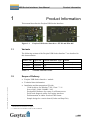
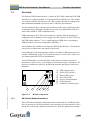
USB Socket Interface+ User Manual Gesytec GmbH Pascalstr. 6 52076 Aachen, Germany Tel. + (49) 24 08 / 9 44-0 Fax + (49) 24 08 / 94 4-100 email: [email protected] www.gesytec.com Doc. ID: LVM/UserDoc/LVM_Manual-EN-v1.0.docx, Version v1.0, 06/30/2014 Easylon USB Socket Interface+ User Manual This manual … … provides you with all the information which you will require to use the Easylon® USB Socket Interface+. However, this manual will neither explain aspects of Echelon's® LONWORKS® technology, nor details of the ISO/IEC 14908 standard on which this product is based, nor Echelon's Microprocessor Interface Program (MIP). The drivers of the USB Socket Interface+ have been developed in compliance with the driver specifications of the Echelon Corporation. Details of these are as well not described in this documentation. For further information on the LONWORKS technology please refer to the extensive documentation provided by Echelon. After a general presentation of the Easylon USB Socket Interface+ in Chapter 1, Chapter 2 describes the necessary steps to install the module. Chapter 3 gives the technical specifications of the device. LVM/UserDoc/LVM_Manual-EN-v1.0.docx, v1.0, 06/30/2014 Chapter 4 provides some information on the usage of the Interface+ as virtual MIP network node. This documentation is subject to changes without notice. Gesytec assumes no responsibility or liability for any errors or inaccuracies that may appear in this document. Gesytec shall have no liability or responsibility to the original purchaser or any other person or entity with respect to any claim, loss, liability, or damage caused or alleged to be caused directly or indirectly by any Gesytec product or the accompanying documentation. Easylon is registered trademark of Gesytec GmbH. Echelon, LON, LonMaker, LONWORKS, and NEURON are registered trademarks of Echelon Corporation. Windows is a registered trademark of Microsoft. Other names may be trademarks of their respective companies. 2/20 Easylon USB Socket Interface+ User Manual Contents Contents Product Information ..........................................................................................................4 1.1 Variants ..................................................................................................................4 1.2 Scope of Delivery ..................................................................................................4 1.3 Overview ................................................................................................................5 1.3.1 VNI (Virtual Network Interface) ...........................................................................5 1.3.2 MIP ........................................................................................................................6 2 Installation ..........................................................................................................................7 2.1 Hardware Installation .............................................................................................7 2.2 Driver Installation ..................................................................................................7 2.2.1 Driver for Windows Operating System (WDM Drivers) ......................................7 2.2.1.1 Installation using the Windows Assistant ..............................................................8 2.2.1.2 Manual Installation and Update ...........................................................................10 2.2.1.3 Driver Instances ...................................................................................................10 2.2.1.4 Settings .................................................................................................................10 2.2.1.5 De installation ......................................................................................................13 2.2.2 Windows and 16 Bit Applications .......................................................................13 2.2.3 EasyCheck – Quick Interface Diagnosis..............................................................13 3 Technical Description ......................................................................................................15 3.1 Network Interface ................................................................................................15 3.2 USB Interface.......................................................................................................15 3.3 LED Signals .........................................................................................................15 3.4 Connector Pin Assignment ..................................................................................16 3.5 Technical Specifications ......................................................................................16 4 Programming Information ..............................................................................................18 4.1 LONWORKS Network Node..................................................................................18 4.2 Registry Key ........................................................................................................18 5 List of Figures ...................................................................................................................19 6 List of Tables ....................................................................................................................19 7 Index ..................................................................................................................................20 LVM/UserDoc/LVM_Manual-EN-v1.0.docx, v1.0, 06/30/2014 1 3/20 Easylon USB Socket Interface+ User Manual 1 Product Information Product Information This manual describes the Easylon USB Socket Interface+ Figure 1-1 1.1 Easylon USB Socket Interface+1 FT-X2 and EIA-485 Variants The following variants of the Easylon USB Socket Interface+ are described in this documentation. Order Code Type Code Network Interface Type Remark P.V20503 P.V10506 P.V20506 Table 1-1 LVM/UserDoc/LVM_Manual-EN-v1.0.docx, v1.0, 06/30/2014 1.2 LVM.DBA EIA-485 LVM.FBA FTX LVM.FAA. FTX extended temperature extended temperature Variants and order-codes Scope of Delivery Easylon USB Socket Interface+ module Technical short information Installation and documentation CD with – 32/64 bit driver for Windows2 XP / Vista / 7 / 8 / Server 2003 / 2008 / 2008R2 / 2012 – Easylon RNI Software for remote LONWORKS access – EasyCheck diagnosis utility for Easylon interfaces – Documentation in Adobe Acrobat .PDF format – Sample design for a carrier board (Gerber and Step files) 1 Modification of connectors on request 2 A Linux driver is available in source code on demand 4/20 Easylon USB Socket Interface+ User Manual 1.3 Product Information Overview The Easylon USB Socket Interface+ realizes an IEC14908 compliant LON-USB connection as a plug-in module, to be integrated into OEM devices. The module is a network interface link between a PC and a control network according to the abovementioned standard respectively the LONWORKS specifications. As an Easylon Interface+ the network interface provides up to eight logical driver interfaces thus realizing the parallel access of several applications to the network either in MIP or LNS compatible mode. USB connection to the CPU board is made by a 10pin connector designed according the ASUS standard. Power supply uses this connector as well. The Easylon USB Socket Interface+ is a so called high speed USB device according to USB standard 2.0, however compatible with USB 1.1. An Evaluation Kit available to the Easylon USB Socket Interface+ which allows easy access to connections and signals of the board. Concerning the LON connection the module is available in different transceiver variants. Additionally to the FT-X2 transceiver there is an EIA-485 variant. Service button and traffic LED are implemented. As an OEM module a certain flexibility with respect to customer specific requirements is observed, e.g. with respect to the connector types or positions. The respective module may therefore be different from the description in this documentation. LVM/UserDoc/LVM_Manual-EN-v1.0.docx, v1.0, 06/30/2014 (1) (2) (3) (4) (5) (6) (7) 1 Figure 1-2 1.3.1 2 3 4 5 6 USB connector pin 1 Traffic LED (yellow) Status LED (green) Error LED (red) Service pin push button GND connector LonWorks connector pin 1 7 Module components VNI (Virtual Network Interface) With VNI Echelon defined a transparent mode of operation for LonWorks interfaces. In this mode LonTalk packets are not preprocessed on the interface device, but the PC realized the complete network access. Thus the applications running 5/20 Easylon USB Socket Interface+ User Manual Product Information on the PC receives and sends the messages. VNI interfaces overcome several limitations of the conventional interfaces using MIP or NSI firmware. For instance they offer an increased performance. Easylon Interfaces+ are compatible with the Echelon VNI interfaces and can be used with LNS based software such as LonMaker for Windows without problems. 1.3.2 MIP LVM/UserDoc/LVM_Manual-EN-v1.0.docx, v1.0, 06/30/2014 The Neuron Chip used on the conventional network interface requires a firmware to realize the interface functionality. The de facto standard was the MIP firmware. Many applications still use the functionality of this firmware, which realizes layers 3–5 of the LonTalk protocol, namely network, transport and session. Using the drivers of the Easylon VNI Interfaces (Interface+) up to 8 logical MIP interfaces can be used with one interface card, i.e. an Easylon VNI Interface replaces 8 standard MIP interface cards. 6/20 Easylon USB Socket Interface+ User Manual 2 Installation Installation Please check the delivered items. You must find the Easylon USB Socket Interface+ and an installation CD, containing drivers and this documentation. 2.1 Hardware Installation Please refer also to the manual describing the device into which you want to insert the Easylon USB Socket Interface+. Turn off power, open the device and plug the USB module into a suitable USB socket. Please observer chapter “3.4 Connector Pin Assignment”. Restart the PC after the module has been installed and insert the Drivers & Documentation CD in order to get the appropriate driver. 2.2 Driver Installation Drivers for different operating systems are available for the Easylon USB Socket Interface+. Currently these are Windows XP, Vista, 7 and 8 and the Windows Server OS 2003, 2008, 2008 R2 and 2012. The drivers support both, the 32 and the 64 bit version of these operating systems. Latest driver versions you can download via the Easylon Support pages of our web site: www.gesytec.com. A Linux driver is available in source code on request. Installation for different operating systems is described in the following sections. Windows operating systems section 2.2.1 16-Bit driver under 32-bit Windows section 2.2.2 This section also describes in short the diagnosis utility „EasyCheck“, which can be installed separately from CD. LVM/UserDoc/LVM_Manual-EN-v1.0.docx, v1.0, 06/30/2014 2.2.1 Driver for Windows Operating System (WDM Drivers) This section describes installation and setup of the Easylon Interface card drivers for the Windows operating system from XP onwards. The setup program is using the same WDM driver (Windows Driver Model) for all operating systems. Note: For installation you can either use the Windows assistant or the program FastUpd.exe for manual installation, which is much more straightforward (cf. chapter 2.2.1.2). 7/20 Easylon USB Socket Interface+ User Manual Installation The latter is especially helpful if you are running Windows 7 and later or have to install several instances of the driver. 2.2.1.1 Installation using the Windows Assistant After the Easylon Interface+ has been mounted Windows will recognize the new device and start the hardware assistant. If Windows should not find the driver on the “Drivers and Documentation” CD or the driver should be elsewhere, please select the appropriate drive and select the setup file “LvxLvu.inf” and the driver “Gesytec Lvuwdm Driver” from the “LvxLvu “ directory. Windows 7 Windows 7 systems connected to the Internet directly start looking for a driver at Windows Update and therefore ignore the CD. Consequently the installation using the assistant will fail and manual settings are required. You can either follow the steps described in 2.2.1.2 “Manual Installation and Update” or proceed as follows: Open the Device Manager (e.g. via the control panel). LVM/UserDoc/LVM_Manual-EN-v1.0.docx, v1.0, 06/30/2014 Right click on the entry for the unknown device and select “Update Drivers”. 8/20 Easylon USB Socket Interface+ User Manual Installation Select “Browse my computer ….” and indicate the drive with the “Drivers & Documentation” CD. Finally give permission for the Gesytec driver setup. Final Steps LVM/UserDoc/LVM_Manual-EN-v1.0.docx, v1.0, 06/30/2014 After successful completion of the installation the device manager will show the interface under „LON Adapters“. Here you will find a „Gesytec LVMx-y...“ entry, with x designating the number of the USB host controller and y the port. If hubs have been cascaded the respective port numbers are given as well. If, after the installation the green LED does not blink an error has occurred in the Easylon USB Socket Interface+ installation. In that case, please restart the PC. The device is now ready to access the LONWORKS network. 9/20 Easylon USB Socket Interface+ User Manual 2.2.1.2 Installation Manual Installation and Update The easiest way to install the driver is to ignore the hardware assistant and run FastUpd.exe from the “Driver/LvxLvu” folder of the CD-ROM. If the “Drivers & Documentation” CD interface has opened in your browser you may access the driver setup as well via “Products” “Easylon USB Socket Interface+” and selecting the button for the operating system. The same program you will use to update an existing driver. 2.2.1.3 Driver Instances The driver consists of a basic part for the interface hardware “LVMx-y”3 and of up to eight logical VNI drivers „LVMx-y-Vniz“ and up to eight logical MIP drivers„LVMx-y-Mipz“. These driver instances can be used like independent network interfaces. For each logical driver instance an individual node-id (unique identification corresponding to the Neuron-ID) is used. VNI and MIP drivers with the last digit z will be assigned the same node-id. There is a maximum of 8 node-id available for each interface device. 2.2.1.4 Settings LVM/UserDoc/LVM_Manual-EN-v1.0.docx, v1.0, 06/30/2014 There are further settings available for the Easylon USB Socket Interface+ which may be helpful in certain operating conditions. They can be found in the “LON Adapters” section of the device manager. Select the properties of the desired device. The „Advanced Properties“ offer the following settings: 3 x is designating the number of the USB host controller and y the port. If hubs have been cascaded the respective port num- bers are given as well. 10/20 Easylon USB Socket Interface+ User Manual Installation Debug Flag The value comprises a DWORD in hexadecimal notation of different flags for debug purposes. Usually it is set to 0 (not existing). Setting the single bits will turn on special debug features. In the current driver versions bits 1 and 3 are used. Note Bit 1: LON telegrams at the interface from and to the USB bus are shown in debug output. Bit 3: CREATE and CLOSE) of the driver are displayed in the debug output. The debug output for instance can be displayed using the DebugView program, which is freely available at www.sysinternals.com. Number of Mip-Interfaces LVM/UserDoc/LVM_Manual-EN-v1.0.docx, v1.0, 06/30/2014 The number of virtual MIP-Interfaces can be set here (0 – 8, default = 2). Number of VNI-Interfaces The number of virtual VNI-Interfaces (Interfaces+) can be set here (0 – 8, default = 1). ATTENTION There are 8 node-IDs available for each interface device. These have to be assigned appropriately to the applications using the device either as VNI or as a MIP interface. If, for example, a VNI application is using the instance LVMx-yVni0 with its corresponding node-id, a MIP application must not use the instance 11/20 Easylon USB Socket Interface+ User Manual Installation LVMx-y-Mip0. VNI applications (e.g. LNS) usually generate a node-id of their own, which will then be additional to the 8 standard node-id belonging to the interface device. Permitted Power Saving Usually the LON USB adapter allows a standby mode with applications running (Standby). At certain conditions however, (e.g. LON USB adapter using a hub under Windows 2000) the current supply to the USB adapter will be shortly interrupted during return from the standby mode by the hub. Under such conditions the standby mode must be turned off (None). Parameters for logical instance Adapter Name LVM/UserDoc/LVM_Manual-EN-v1.0.docx, v1.0, 06/30/2014 An arbitrary name can be chosen freely (e.g. building 7). NOTE This name must not be used by another instance. If the name is already in use, the device will not start (code 10). Debug Flag This field contains a DWORD in hexadecimal notation of different flags for debug purposes. Usually it is set to 0 (= not existing). By setting the single bits certain debug features can be turned on. At the moment the bits 0, 1 and 3 are used: Bit 0: LON telegrams at the interface from and to the application are displayed in the debug output. 12/20 Easylon USB Socket Interface+ User Manual Installation Bit 1: Telegrams at the interface between PC and interface hardware are displayed in the debug output. Bit 3: CREATE and CLOSE of the driver are displayed in the debug output. No of Parallel Transactions By default the Easylon MIP driver will handle 16 parallel transactions. This feature can be turned off by setting the value to 1. 2.2.1.5 De installation WDM drivers are de installed using the “Device Manager”. Among “LON Adapters” select the “Gesytec LVMx-yy” driver and click “de-install”. 2.2.2 Windows and 16 Bit Applications The Windows driver for the 32 bit Windows versions also provides a 16 bit interface. (Unfortunately Microsoft does not support this in the 64 bit versions.) To use it, the following entry has to be made in the file „config.nt“, usually found in the windows\system32 directory: Device=%SystemRoot%\system32\ lpxdos.exe –Llvu1-2-Mip0 The 32 bit LON device used is specified by the optional –L or /L parameter: /Lname name = lvu1-2-Mip0 Note: for device LVU at USB host controller 1 and with port number 2 at USB root hub Two subsequent “l” characters have to be entered, one indicating the parameter L, the second as first character of the name: –Llxxxx LVM/UserDoc/LVM_Manual-EN-v1.0.docx, v1.0, 06/30/2014 The 16 bit LON device used is specified by the following optional parameter: /Dn with n = 1...9 for LON1 to LON9 Without this parameter, the interface will be assigned the first unused name starting with “LON1”. 2.2.3 EasyCheck – Quick Interface Diagnosis In addition to the drivers, the test utility “EasyCheck” can be installed in the respective program directory (default: : \Easylon\Lpx ). The program checks inter- 13/20 Easylon USB Socket Interface+ User Manual Installation face and software environment and displays information, from which can be concluded on the reasons for problems in connection with the interface. LVM/UserDoc/LVM_Manual-EN-v1.0.docx, v1.0, 06/30/2014 The program “EasyCheck” runs an analysis of the system’s software. It will open the selected interface, check the driver version and display it. By sending a “query status” command the communication with the hardware is tested. Using the “read memory” command the utility will show if the device is running MIP or NSI firmware. Properly installed Easylon Interfaces will send a corresponding answer. 14/20 Easylon USB Socket Interface+ User Manual 3 3.1 Technical Description Technical Description Network Interface Easylon Interface+ cards are using an FPGA for accessing the control network. For which sufficient RAM is available as network buffer for transmit and receive. For use in protocol analysis each packet received is transmitted to the application with timestamp of 1 ms accuracy. The FPGA is connected to the computer bus. Eight node-ids are available on the interface for identification within the control network (cf. “Driver Instances”). The interface status is signaled by a status LED. The Service push button is read by the driver software (Figure 1-2). 3.2 USB Interface The Easylon USB Interface+ has been developed according to USB 2.0 standard, high speed. It can as well operate at USB 1.1 interfaces. 3.3 LED Signals Position cf. Figure 1-2 Green Red blinking: in normal operation blinking firmware is loaded ON error, e.g. after reset If both LEDs are off, the module is out of operation Traffic LED yellow signals network traffic LVM/UserDoc/LVM_Manual-EN-v1.0.docx, v1.0, 06/30/2014 Staus LED Error LED 15/20 Easylon USB Socket Interface+ User Manual 3.4 Technical Description Connector Pin Assignment USB connector PIN 1 2 3 4 5 6 7 8 9 10 Table 3-1 Description +5 Volt +5 Volt USB USB + GND GND Pin assignment of 10 pin USB connector LON connector PIN 1 2 3 Table 3-2 MNEMO RT + GND RT - Description LON data + ground LON data – Pin assignment of 3pin LON connector Pin 1 position cf. Figure 1-2 3.5 Technical Specifications LVM/UserDoc/LVM_Manual-EN-v1.0.docx, v1.0, 06/30/2014 USB Interface Type USB slave interface accord. to high speed USB standard 2.0 Connector 10 pin 2 row edge connector Network Interface Transceiver FT-X2, electrically isolated EIA-485, not electrically isolated, 1.25 Mbps max. Connector 3 pin edge connector 16/20 Easylon USB Socket Interface+ User Manual Technical Description Power Supply Power Supply 5 V DC +-10%, externally via USB connector Power Consumption < 100 mA, typically Operating Conditions Temperature Operation extended range Storage 0 ºC – +70 ºC (only for FTX version) -40 ºC – +85 ºC -40 ºC – +85ºC Humidity 90%, no condensation Display and Operation service push button traffic LED (yellow) status LED (green) error LED (red) Dimensions Board 69.34 x 36.96 [mm] For easy integration a step file of the board is available. Conformity 2011/65/EU LVM/UserDoc/LVM_Manual-EN-v1.0.docx, v1.0, 06/30/2014 RoHs 17/20 Easylon USB Socket Interface+ User Manual 4 4.1 Programming Information Programming Information LONWORKS Network Node Being an IEC14908 compatible interface device the Easylon Interface+ card can be used as a network node in a LONWORKS network. The Interface+ can realize one or more virtual MIP interfaces. As the external interface file (.xif) required for using the device as a network node can only be created for a specific application an example .xif file is provided. This must be adapted with the XIF editor prior to usage. The file can be found on the “Drivers & Documentation” CD. Network Interface TP/FT for virtual MIP interfaces Table 4-1 4.2 Transmission Rate 78 kbps XIF –File lolv075f.xif Network access and .xif files Registry Key The driver of the Easylon USB Socket Interface+ makes an entry in the registry database for each found device, according to Echelon’s guidelines. You will find this entry at: \\HKEY_LOCAL_MACHINE\Software\LonWorks\DeviceDrivers. LVM/UserDoc/LVM_Manual-EN-v1.0.docx, v1.0, 06/30/2014 For each Easylon USB Socket Interface+ you will find a key with the device name (Gesytec LVMx-y...) and a character value with the driver name. 18/20 Easylon USB Socket Interface+ User Manual 5 List of Figures List of Figures Figure 1-1 Easylon USB Socket Interface+ FT-X2 and EIA-485 ....................................... 4 Figure 1-2 Module components ........................................................................................... 5 6 List of Tables Variants and order-codes ................................................................................... 4 Table 3-1 Pin assignment of 10 pin USB connector ........................................................ 16 Table 3-2 Pin assignment of 3pin LON connector ........................................................... 16 Table 4-1 Network access and .xif files ........................................................................... 18 LVM/UserDoc/LVM_Manual-EN-v1.0.docx, v1.0, 06/30/2014 Table 1-1 19/20 Easylon USB Socket Interface+ User Manual 7 Index Index product information 4 programming instructions 18 registry key 18 RoHs 17 scope of delivery 4 service LED 15 standby 12 step file 17 technical specifications 16 temperature 17 transceiver 16 Update 10 USB interface 15 USB standard 5 variants 4 Virtual Network Interface 5 VNI 5 Windows 2000 13 7 8 Vista 13 XP 13 xif file 18 LVM/UserDoc/LVM_Manual-EN-v1.0.docx, v1.0, 06/30/2014 16 bit applications 13 Adapter Name 12 adapter settings 10 connector 16 connector pin assignment 16 debug flag 11 Debug Flag 12 dimension 17 dirver 4 driver installation 7 driver instances 10 EasyCheck 13 installation 7 manual 8, 10 LED 17 LED signals 15 MIP 6 network interface 15 No of Parallel Transactions 13 Number of MIP-Interfaces 11 Number of VNI-Interfaces 11 order code 4 power consumption 17 power supply 17 20/20