1
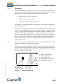
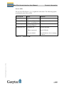
Mini PCIe Socket Interface User Manual Gesytec GmbH Pascalstr. 6 52076 Aachen, Germany Tel. + (49) 24 08 / 9 44-0 Fax + (49) 24 08 / 94 4-100 email: [email protected] www.gesytec.com Doc. ID: LPD/UserDoc/LPD-Manual-EN-v1.2.docx, Version v1.2, 07/02/14 Easylon Mini PCIe Socket Interface User Manual This manual … … provides you with all the information which you will require to use the Easylon® Mini PCIe Socket Interface. However, this manual will neither explain aspects of Echelon's® LONWORKS® technology, nor Echelon's Microprocessor Interface Program (MIP) used on this network interface card. The drivers of the Mini PCIe Socket Interface have been developed in compliance with the driver specifications of the Echelon Corporation Details of these are as well not described in this documentation. For further information on the LONWORKS technology please refer to the extensive documentation provided by Echelon. After a general presentation of the Easylon Mini PCIe Socket Interface in Chapter 1, Chapter 2 describes the necessary steps to install the module. LPD/UserDoc/LPD-Manual-EN-v1.2.docx v1.2, 07/02/14 Chapter 3 gives the technical specifications of the device and Chapter 4 provides some programming instruction for operation under Windows CE. Tips and tricks concerning the operation can be found in Chapter 5. This documentation is subject to changes without notice. Gesytec assumes no responsibility or liability for any errors or inaccuracies that may appear in this document. Gesytec shall have no liability or responsibility to the original purchaser or any other person or entity with respect to any claim, loss, liability, or damage caused or alleged to be caused directly or indirectly by any Gesytec product or the accompanying documentation. Easylon is registered trademark of Gesytec GmbH. Echelon, LON, LonMaker, LONWORKS, and NEURON are registered trademarks of Echelon Corporation. Windows is a registered trademark of Microsoft. Other names may be trademarks of their respective companies. The Easylon Mini PCIe Socket Interface incorporates the MIP program by Echelon Corporation. The aforesaid company holds all rights relating to this software. 2/27 Easylon Mini PCIe Socket Interface User Manual Contents LPD/UserDoc/LPD-Manual-EN-v1.2.docx v1.2, 07/02/14 Contents 1 Product Information ..........................................................................................................4 1.1 Variants ..................................................................................................................4 1.2 Scope of Delivery ..................................................................................................4 1.3 Overview ................................................................................................................5 2 Installation ..........................................................................................................................7 2.1 Hardware Installation .............................................................................................7 2.1.1 Pin Assignment ......................................................................................................7 2.1.1.1 Mini PCIe Connector .............................................................................................7 2.1.1.2 LON Connector ......................................................................................................9 2.2 Driver Installation ..................................................................................................9 2.2.1 Driver for Windows Operating System (WDM Drivers) ....................................10 2.2.1.1 Installation............................................................................................................10 2.2.1.2 Manual Installation and Update ...........................................................................14 2.2.1.3 Settings .................................................................................................................14 2.2.2 Windows and 16 Bit Applications .......................................................................16 2.2.3 EasyCheck – Quick Interface Diagnosis..............................................................17 2.2.4 Windows CE Driver.............................................................................................17 3 Technical Specifications ..................................................................................................18 4 Programming Instructions ..............................................................................................20 4.1 Windows CE Application Interface .....................................................................20 4.1.1 CreateFile .............................................................................................................20 4.1.2 CloseHandle .........................................................................................................20 4.1.3 ReadFile ...............................................................................................................20 4.1.4 WriteFile ..............................................................................................................21 4.1.5 GetVersion ...........................................................................................................21 4.1.6 ReadFile with Timeout ........................................................................................22 4.1.7 Set Timeout for ReadFile .....................................................................................23 4.1.8 Registry entries for Easylon USB Interface .........................................................23 5 Tips and Tricks ................................................................................................................25 5.1 Standby Mode of PC ............................................................................................25 5.2 Hibernation Mode of PC ......................................................................................25 5.3 Registry Key ........................................................................................................25 6 List of Figures ...................................................................................................................26 7 List of Tables ....................................................................................................................26 8 Index ..................................................................................................................................27 3/27 Easylon Mini PCIe Socket Interface User Manual 1 Product Information Product Information This manual describes the Easylon Mini PCIe Socket Interface Figure 1-1 1.1 Easylon Mini PCIe Socket Interface FTX and EIA-485 Variants The following variants of the Easylon Mini PCIe Socket Interface are described in this documentation. Order Code Transceiver Neuron Firmware Remark P.P20A03 P.P10506-3 MIP MIP Table 1-1 LPD/UserDoc/LPD-Manual-EN-v1.2.docx v1.2, 07/02/14 1.2 EIA-485 FTX extended temperature range extended temperature range Variants and order-codes Scope of Delivery Easylon Mini PCIe Socket Interface module with Echelon MIP firmware Technical brief information Installation and documentation CD with – 32 bit driver for Windows1 2000 / XP / Vista / 7 / 8 / Server 2003 / 2008 / 2008R2 / 2012 – 64 bit driver for Windows XP / Vista/ 7 / 8 / Server 2003 / 2008 / 2008R2 / 2012 – Easylon RNI Software for remote LONWORKS access – EasyCheck diagnosis utility for Easylon interfaces – Documentation in Adobe Acrobat .PDF format 1 A Linux driver is available in source code on demand 4/27 Easylon Mini PCIe Socket Interface User Manual 1.3 Product Information Overview The Easylon Mini PCIe Socket Interface realizes a LonWorks-USB interface in the design of a PCIe ”Full-Mini Card with bottom side keep outs (F2)“. It can be used in devices offering a Mini PCIe socket of the following type: Full-Mini-Only Socket (connector A) Dual-Use Socket (connector A) Dual Head-to-Head-Socket (connector A) The module uses the USB interface of the Mini PCIe slot and thus implements a LON USB interface. The module of 51 x 30 mm features a Neuron FT5000 processor and an FT-X2 transceiver running MIP firmware to connect to the LonWorks network. Alternatively a version with EIA-485 transceiver and Neuron 5000 is available. Service and traffic LED signals are available via the socket connector; a service button has to be connected externally. Status, error and service LEDs are on board. In the FTX version the LON interface is galvanically separated from the Mini PCI Express ground. The module has been designed for an extended temperature range of -40 to +85 °C. Note Due to the usage of the Neuron FT5000 or Neuron 5000 with MIP firmware this module is not suited for LNS based applications. The driver for the Easylon Mini PCIe Socket Interface is compliant with Echelon’s driver interface. Applications using the driver interface directly can use the interface without problems. The Easylon Mini PCIe Socket Interface is compatible with Gesytec’s WLDV32.DLL. LPD/UserDoc/LPD-Manual-EN-v1.2.docx v1.2, 07/02/14 (1) (2) (3) (4) (5) 1 2 Figure 1-2 3 4 Service LED, yellow Status LED, green Error LED, red type sticker on rear side LonWorks connector 5 Module components 5/27 Easylon Mini PCIe Socket Interface User Manual Product Information Service LED The service LED (Figure 1-2, (1)) signals the card status. The following signals are defined for the service LED: Service LED Flash (1 Hz) Blink (1/2 Hz) Permanently ON Permanently OFF Remarks Error Configure the node. Normal operation check USB side check Windows device manager for driver Service LED LPD/UserDoc/LPD-Manual-EN-v1.2.docx v1.2, 07/02/14 Table 1-2 Status No Neuron communication Driver installed, node is “unconfigured” Node is „applicationless“ and „unconfigured“. Installation ok or USB not connected or driver not loaded 6/27 Easylon Mini PCIe Socket Interface User Manual 2 Installation Installation Please check the delivered items. You must find the Easylon Mini PCIe Socket Interface and an installation CD, containing drivers and this documentation. 2.1 Hardware Installation Please refer also to the manual describing the device into which you want to insert the Easylon Mini PCIe Socket Interface. Turn off power, open the device and mount the module in a suitable Mini PCIe socket. Please observer the following chapter “Pin Assignment”. Restart the PC after the module has been installed and insert the Drivers & Documentation CD in order to get the appropriate driver (cf. chapter 2.2). 2.1.1 Pin Assignment 2.1.1.1 Mini PCIe Connector LPD/UserDoc/LPD-Manual-EN-v1.2.docx v1.2, 07/02/14 The Mini PCIe connector is used according to the standard. 7/27 Easylon Mini PCIe Socket Interface User Manual Pin Name 51 49 47 45 43 Reserved Reserved Reserved Reserved GND 41 39 +3.3Vaux +3.3Vaux Supply Supply 37 35 33 31 29 27 25 23 21 19 GND GND PETp0 PETn0 GND GND PERp0 PERn0 GND Reserved (UIM_C4) Reserved (UIM_C8) 17 15 13 11 9 7 5 3 1 GND REFCLK+ REFCLKGND CLKREQ# COEX2 COEX1 WAKE# Table 2-1 Installation Mini PCIe Pin Socket Interface nc 52 Name +3.3Vaux Mini PCIe Socket Interface Supply nc nc nc GND 50 48 GND +1.5V GND nc 46 44 42 LED_WPAN# LED LON TX LED_WLAN# LED LON RX LED_WWAN# LED Service + button 40 GND GND GND GND nc nc GND GND nc nc GND nc 38 36 USB_D+ USB_D- USB 2.0 USB 2.0 34 32 30 28 26 GND SMB_DATA SMB_CLK +1.5V GND GND nc nc nc GND 24 22 +3.3Vaux PERST# Supply System reset input 20 W_DISABLE# nc nc 18 GND GND Mechanical GND nc nc GND nc nc nc nc Key 16 14 12 10 8 6 4 UIM_VPP UIM_RESET UIM_CLK UIM_DATA UIM_PWR 1.5V GND nc nc nc nc nc nc GND 2 3.3Vaux Supply Pin assignment of Mini PCIe connector LPD/UserDoc/LPD-Manual-EN-v1.2.docx v1.2, 07/02/14 External LED outputs and service button input Outputs 42, 44, 46 are active low Open Drain and can switch a maximum of 9 mA as per standard. Attention: The external LEDs have to be supplied by the same 3.3 V source as the module. This is very important to avoid any latch up problems Pin 42 (LED_WWAN) has got an additional internal pullup resistor against 3.3 V. 8/27 Easylon Mini PCIe Socket Interface User Manual Installation Pin 42 (LED_WWAN) is output for an LED and LON service button input at the same time. Der button is connected to pin 42 and GND. Closing it will release the service message. 2.1.1.2 LON Connector PIN 1 2 3 Table 2-2 PIN 1 2 3 Table 2-3 MNEMO RT + GND RT - Description LON data + ground LON data – Pin assignment of 3pin LON connector, FTX version MNEMO RT + GND RT - Description LON data + Connected to ground of Mini PCIe connector LON data – Pin assignment of 3pin LON connector, EIA-485 variant The LON connector is a 90° multi-pin connector, 1 row, 3pin, 1.25 mm; Manufacturer: PanelMate Molex 0537800370 Supplier e,g. Digikey: WM7601DKR-ND A LON connection cable is not part of the delivery. For cable assembly the following parts are required: Description Connector casing straight, 1 row 3pin, 1.25mm Crimp contakt 28-30 AWG gold for 1.25mm Crimping tool for 1.25mm connector system LPD/UserDoc/LPD-Manual-EN-v1.2.docx v1.2, 07/02/14 2.2 Manufacturer PanelMate Molex: 51146-0300 PanelMate Molex: 0506418141 Molex: 0638117900 Supplier e.g. Digikey: WM5401-ND Digikey: WM5506-ND Digikey: WM9805-ND Driver Installation Drivers for different operating systems are available for the Easylon Mini PCIe Socket Interface. Currently these are Windows 2000, XP, Vista, 7 and 8 and the Windows Server OS 2003, 2008, 2008 R2 and 2012. The drivers support both, the 32 and the 64 bit version of these operating systems. Latest driver versions you can download via the Easylon Support pages of our web site: www.gesytec.com. A Linux driver is available in source code on request. 9/27 Easylon Mini PCIe Socket Interface User Manual Installation Installation for different operating systems is described in the following sections. Windows operating systems section 2.2.1 Windows CE section 2.2.4 16-Bit driver under 32-bit Windows section 2.2.2 This section also describes in short the diagnosis utility „EasyCheck“ which can be installed separately from CD. 2.2.1 Driver for Windows Operating System (WDM Drivers) This section describes installation and setup of the Easylon Interface card drivers for the Windows operating system from XP onwards. The setup program is using the same WDM driver (Windows Driver Model) for all Windows operating systems. Note: For installation you can either use the Windows assistant or the program FastUpd.exe for manual installation, which is much more straightforward (cf. chapter 2.2.1.2). The latter is especially helpful if you are running Windows 7 and later or have to install several instances of the driver. 2.2.1.1 Installation Insert the “Drivers & Documentation” CD into the drive of your PC with the module plugged into the desired socket. LPD/UserDoc/LPD-Manual-EN-v1.2.docx v1.2, 07/02/14 The PC will show that a new USB device has been found. Windows will automatically start the hardware wizard. 10/27 Easylon Mini PCIe Socket Interface User Manual Installation Windows systems up to and including XP LPD/UserDoc/LPD-Manual-EN-v1.2.docx v1.2, 07/02/14 Choose not to browse Windows Update and click the Next> button to start the driver installation using this assistant or Cancel and install manually (cf. chapter 2.2.1.2). Having decided for automatic installation please continue by clicking the Next> button. The installation process is shown. 11/27 Easylon Mini PCIe Socket Interface User Manual Installation After the installation has been finished, the above message is shown. Click the Finish> button to terminate the installation procedure. It is possible, that you get be asked to restart the computer. LPD/UserDoc/LPD-Manual-EN-v1.2.docx v1.2, 07/02/14 Windows 7 Windows 7 systems directly start looking for a driver at Windows Update and therefore ignore the CD. Consequently the installation using the assistant will fail and manual settings are required. You can either follow the steps described in 2.2.1.2 “Manual Installation and Update” or proceed as follows: Open the Device Manager (e.g. via the control panel). 12/27 Easylon Mini PCIe Socket Interface User Manual Installation Right click on the entry for the unknown device and select “Update Drivers”. Select „Browse my computer ….“ And indivate the drive with the “Drivers & Documentation” CD. Finally give permission for the Gesytec driver setup. Final Steps LPD/UserDoc/LPD-Manual-EN-v1.2.docx v1.2, 07/02/14 After successful completion of the installation the device manager will show the interface under „LON Adapters“. 13/27 Easylon Mini PCIe Socket Interface User Manual Installation Here you will find a „Gesytec LONUSB x-y...“ entry, with x designating the number of the USB host controller and y the port. If hubs have been cascaded the respective port numbers are given as well. If, after the installation the green LED does not blink an error has occurred in the Easylon Mini PCIe Socket Interface installation. In that case, please disconnect the module from the PC and reconnect after a short period of not less than 10 s. During the installation and at each Neuron reset the red LED is shortly flashing. The device is now ready to access the LONWORKS network. 2.2.1.2 Manual Installation and Update The easiest way to install the driver is to ignore the hardware assistant and run FastUpd.exe from the “Driver/LonUsb” folder of the CD-ROM. If the “Drivers & Documentation” CD interface has opened in your browser you may access the driver setup as well via “Products” “Easylon Mini PCIe Socket Interface” and selecting the button for the operating system. The same program you will use to update an existing driver. A new version will be installed on the PC within a few seconds. In order to update the firmware in the device as well, you must disconnect the Mini PCIe Socket Interface and reconnect it again. 2.2.1.3 Settings LPD/UserDoc/LPD-Manual-EN-v1.2.docx v1.2, 07/02/14 There are further settings available for the Easylon Mini PCIe Socket Interface which may be helpful in certain operating conditions. They can be found in the Universal Serial Bus Controller section of the device manager. Select the properties of the desired device. The „Advanced Properties“ offer the following settings: 14/27 Easylon Mini PCIe Socket Interface User Manual Installation Lon Adapter This will assign a name „LON1“ ... „LON9“ to the LON USB adapter, which certain application will require. Remember that the name must not be in use by any other device driver. In case of a name conflict the device cannot be started. (Code 10). LPD/UserDoc/LPD-Manual-EN-v1.2.docx v1.2, 07/02/14 Adapter Name Alternatively an arbitrary name can be assigned to the adapter (e.g. floor 7). If both „Lon Adapter“ and „Adapter Name“ are assigned to the same device only the entry for „Lon Adapter“ will be used. Debug Flag The value comprises a DWORD in hexadecimal notation of different flags for debug purposes. Usually it is set to 0 (not existing). Setting the single bits will turn on special debug features. In the current driver versions bits 0, 1 and 3 are used. Bit 0: LON telegrams at the interface from and to the application are shown in debug output. Bit 1: LON telegrams at the interface from and to the USB bus are shown in debug output. 15/27 Easylon Mini PCIe Socket Interface User Manual Note Installation Bit 2: Reserved for Easylon Watcher. Bit 3: CREATE and CLOSE) of the driver are displayed in the debug output. The debug output for instance can be displayed using the DebugView program, which is freely available at www.sysinternals.com. Permitted Power Saving Usually the LON USB adapter allows a standby mode with applications running (Standby). At certain conditions however, (e.g. LON USB using an external hub under Windows 2000) the current supply to the LON USB adapter will be shortly interrupted during return from the standby mode by the external hub. Under such conditions a standby mode must be turned off (None). 2.2.2 Windows and 16 Bit Applications The Windows driver for the 32 bit Windows versions also provides a 16 bit interface. (Unfortunately Microsoft does not support this in the 64 bit versions.) To use it, the following entry has to be made in the file „config.nt“, usually found in the windows\system32 directory: Device=%SystemRoot%\system32\ lpxdos.exe –Llonusb1-2 The 32 bit LON device used is specified by the optional –L or /L parameter: /Lname name = lonusb1-2 LPD/UserDoc/LPD-Manual-EN-v1.2.docx v1.2, 07/02/14 Note: for device LONUSB at USB host controller 1 and with port number 2 at USB root. If several hubs have been cascaded the respective port numbers have to be provided as well. Two subsequent “l” characters have to be entered, one indicating the parameter L, the second as first character of the name: –Llxxxx The 16 bit LON device used is specified by the following optional parameter: /Dn with n = 1...9 for LON1 to LON9 Without this parameter, the interface will be assigned the first unused name starting with “LON1”. 16/27 Easylon Mini PCIe Socket Interface User Manual 2.2.3 Installation EasyCheck – Quick Interface Diagnosis In addition to the drivers, the test utility “EasyCheck” can be installed in the respective program directory (default: : \Easylon\Lpx ). The program checks interface and software environment and displays information, from which can be concluded on the reasons for problems in connection with the interface. The program “EasyCheck” runs an analysis of the system’s software. It will open the selected interface, check the driver version and display it. By sending a “query status” command the communication with the hardware is tested. Using the “read memory” command the utility will show if the device is running MIP or NSI firmware. Properly installed Easylon Interfaces will send a corresponding answer. 2.2.4 Windows CE Driver The Windows CE driver has been designed for x86 processors. Variants for other processors can be realized on request. There are versions for Windows up to CE 6.0. Note: Prior to using the interface please check if your Windows CE system supports USB. For instance you could connect a standard USB device like mouse, keyboard or memory stick. The Windows CE driver comes is a DLL named lonusb.dll. Like all Windows CE drivers it must be in the Windows directory of your system. The required files can be found on the Driver & Documentation CD under Drivers/Windows CE. If the driver has to be integrated into the Windows CE image, the simplest way is a respective entry in the platform.bib file. This approach is almost the same for all Windows CE versions. LPD/UserDoc/LPD-Manual-EN-v1.2.docx v1.2, 07/02/14 Foe correct operation the driver requires registry entries. These can be found in the file lonusb.reg. In order to integrate the driver into a Windows CE image, the contents of this file has to be copied into the file platform.reg. ; LONUSB - Driver [HKEY_LOCAL_MACHINE\Drivers\USB\LoadClients\3596\Default\De fault\LonUsb] "DLL"="lonusb.dll" "Prefix"="LON" "DebugFlag"=dword:0 "ReadTimeout"=dword:FFFFFFFF 17/27 Easylon Mini PCIe Socket Interface User Manual 3 Technical Specifications Technical Specifications CPU FTX Neuron FT5000 EIA-485 Neuron 5000 Clock 80 MHz Mini PCIe Socket Interface Type Full Mini Card, accord. to PCI Express, Mini Card Electromechanical Specification, Rev 1.2 Connector standard Mini PCI Express connector LONWORKS Interface Transceiver FT-X2, electrically isolated EIA-485, not electrically isolated, 1.25 Mbps max. Connector 3 pin connector, 1.25 mm PanelMate, Molex Power Supply Power supply 3,3V ± 9%, externally via Mini PCIe connector Current consumption < 100 mA, typically Operating Conditions -40 ºC – +85 ºC -40 ºC – +85ºC Temperature operation storage Humidity 90%, no condensation Display and Operation LPD/UserDoc/LPD-Manual-EN-v1.2.docx v1.2, 07/02/14 On board status LED (green) error LED (red) Neuron Service LED (yellow) Externally available signals Neuron Service LED LON traffic LED for RX and TX Externally connectable Neuron Service push button Dimensions Board (standard dimensions) 30.00 x 50.95 [mm] Heights FTX above board 8.18 mm +0,2/-0,08 mm, not compliant to standard 18/27 Easylon Mini PCIe Socket Interface User Manual Technical Specifications Conformity 2011/65/EU LPD/UserDoc/LPD-Manual-EN-v1.2.docx v1.2, 07/02/14 RoHs 19/27 Easylon Mini PCIe Socket Interface User Manual 4 Programming Instructions Programming Instructions 4.1 Windows CE Application Interface Note: Some of the functions described below are marked “obsolete”. These functions and control codes are referenced her only for compatibility with older versions of LPCDRV/LG2DRV and should not be used for development of new software. 4.1.1 CreateFile Opens a LON device. Syntax: ni_handle = CreateFile(szDevName, GENERIC_READ|GENERIC_WRITE, 0, NULL, OPEN_EXISTING, 0, NULL); Parameter SzDevName Return value ni_handle Type TCHAR* Type HANDLE Description Device name, e.g. TEXT("LON1:") Description file handle of the LON device or INVALID_HANDLE_VALUE 4.1.2 CloseHandle Closes a LON device. Syntax: CloseHandle(ni_handle); LPD/UserDoc/LPD-Manual-EN-v1.2.docx v1.2, 07/02/14 Parameter ni_handle 4.1.3 Type HANDLE Description file handle of the LON device that should be closed ReadFile This synchronous function reads a telegram according to the application layer format. Synchronous means the function returns only if the NEURON received the telegram or the handle is closed. The timeout of this blocking call can be changed via registry or via DeviceIoControl. A timeout value of 0 means, that this function returns immediately, if no data are available. 20/27 Easylon Mini PCIe Socket Interface User Manual Programming Instructions Syntax: ReadFile(ni_handle, pMsg, len, &rLen, NULL); Parameter ni_handle pMsg len rlen 4.1.4 Type HANDLE void* DWORD DWORD Description file handle of the LON device pointer to an „explicit message buffer“ length of the buffer [bytes] length of the received telegram [bytes] WriteFile Writes a telegram according to the application layer format. This function returns immediately. Syntax: WriteFile(ni_handle, pMsg, len, &rLen, NULL); 4.1.5 Parameter ni_handle pMsg len rlen Type HANDLE void* DWORD DWORD Description file handle of the LON device pointer to an „explicit message buffer“ length of the buffer [bytes] length of the telegram to be send [bytes] Note: The telegram according to the application layer format contains a length information of the buffer itself. That is why we ignore the parameter len in the use of function ReadFile()and WriteFile(). Note: Use the maximum length (256 bytes) of the buffer while reading a telegram. GetVersion Returns the version number of the driver as Unicode string, e.g. TEXT("Easylon LonUsb Version 1.00 for WinCE from 11/05/2002"). Syntax: LPD/UserDoc/LPD-Manual-EN-v1.2.docx v1.2, 07/02/14 #define IOCTL_LPCDRV_GET_VERSION \ CTL_CODE( FILE_DEVICE_LPCDRV, 0x900, \ METHOD_BUFFERED, FILE_READ_ACCESS ) #define IOCTL_GETVERSION 0x43504C01 result = DeviceIoControl(ni_handle, IOCTL_LPCDRV_GET_VERSION, NULL, 0, szVersion, sizeof(szVersion), BytesReturned, NULL); Parameter ni_handle szVersion Type HANDLE TCHAR* //obsolete Description file handle of the LON device Buffer for version string 21/27 Easylon Mini PCIe Socket Interface User Manual BytesReturned DWORD Return value Type Result BOOL 4.1.6 Programming Instructions length of the string [bytes] = (number of characters + 1) * 2 Description FALSE if buffer is too small, else TRUE ReadFile with Timeout Reads a telegram according to the application layer format. The Timeout parameter determines the functions behavior while the receive buffer is empty: Timeout = 0: function returns immediately Timeout = n: function waits n milliseconds to receive a telegram. Timeout = INFINITE: function works as synchronous function, see also function ReadFile. Syntax: #define IOCTL_LPCDRV_READ_WAIT \ CTL_CODE( FILE_DEVICE_LPCDRV, 0x908, \ METHOD_BUFFERED, (FILE_READ_DATA | FILE_WRITE_DATA) ) result = DeviceIoControl(ni_handle, IOCTL_LPCDRV_READ_WAIT, &timeout, 4, pMsg, len, &rLen, NULL); LPD/UserDoc/LPD-Manual-EN-v1.2.docx v1.2, 07/02/14 #define IOCTL_READ 0x43504C02 // obsolete result = DeviceIoControl(ni_handle, IOCTL_READ, pMsg, len, &timeout, 4, &rLen, NULL); Note: Using IOCTL_READ the Parameters lpInBuffer and lpOutBuffer as well as nInBufferSize and nOutBufferSize are permuted as defined in the API Reference of DeviceIoControl. Parameter ni_handle timeout pMsg len Return value Result Type HANDLE DWORD void* DWORD Type BOOL Description file handle of the LON device Timeout [Milliseconds] pointer to an „explicit message buffer“ length of the buffers [bytes] Description TRUE, if telegram was received FALSE at timeout 22/27 Easylon Mini PCIe Socket Interface User Manual 4.1.7 Programming Instructions Set Timeout for ReadFile Reads a telegram according to the application layer format. The Timeout parameter determines the functions behavior while the receive buffer is empty: Timeout = 0: function returns immediately Timeout = n: function waits n milliseconds to receive a telegram. Timeout = INFINITE: function works as synchronous function, see also function ReadFile. Syntax: #define IOCTL_LPCDRV_SET_READ_TIMEOUT \ CTL_CODE( FILE_DEVICE_LPCDRV, 0x909, \ METHOD_BUFFERED, FILE_WRITE_DATA) result = DeviceIoControl(ni_handle, IOCTL_LPCDRV_READ_WAIT, &timeout, 4, NULL, 0, &rLen, NULL); 4.1.8 Parameter ni_handle timeout Return value Result Type HANDLE DWORD Type BOOL Description file handle of the LON device Timeout [Milliseconds] Description TRUE, if timeout was stored, FALSE if an error has occurred Note: Undefined IOCTL-Codes will return FALSE and set LastError to ERROR_NOT_SUPPORTED. Registry entries for Easylon USB Interface LPD/UserDoc/LPD-Manual-EN-v1.2.docx v1.2, 07/02/14 ; LONUSB - Driver [HKEY_LOCAL_MACHINE\Drivers\USB\LoadClients\3596\Default\De fault\LonUsb] "DLL"="lonusb.dll" "Prefix"="LON" "DebugFlag"=dword:0 "ReadTimeout"=dword:FFFFFFFF DebugFlag The value comprises a DWORD in hexadecimal notation of different flags for debug purposes. Usually it is set to 0 (not existing). Setting the single bits will turn on special debug features. In the current driver versions bits 0 and 1 are used. Bit 0: LON telegrams at the interface from and to the application are shown in debug output. Bit 1: LON telegrams at the interface from and to the USB bus are shown in debug output. 23/27 Easylon Mini PCIe Socket Interface User Manual Programming Instructions LPD/UserDoc/LPD-Manual-EN-v1.2.docx v1.2, 07/02/14 ReadTimeout The value (in milliseconds) comprises a DWORD in hexadecimal notation to affect the behavior of ReadFile(). A value of INFINITE (= 0xffffffff) makes ReadFile() a blocking call. This is the default behavior, if no parameter is given (like lpcdrv, lg2drv). A timeout value of 0 means, that this function returns immediately, if no data are available. 24/27 Easylon Mini PCIe Socket Interface User Manual 5 5.1 Tips and Tricks Tips and Tricks Standby Mode of PC A PC with Easylon Mini PCIe Socket Interface may be set to standby mode, because the device will be powered during standby. However, it was observed that, at returning from the standby mode, the power supply to the interface is shortly interrupted. Dependent on the system this may reinitialize the device. Active applications, which were using the Easylon Mini PCIe Socket Interface before entering standby mode, will then not able to communicate with device any longer. In such configurations please refer to section Settings and set “Permitted Power Saving" to “None” to disable the standby mode. The LON USB driver will then inhibit the standby mode with applications running. 5.2 Hibernation Mode of PC The Easylon Mini PCIe Socket Interface does not support the hibernation mode. When the PC enters hibernation mode, the USB will not be powered any longer. As this would lead to a loss of the Neuron Chip settings the LON USB driver will inhibit Windows from turning into the hibernation mode with applications running. 5.3 Registry Key The driver of the Easylon Mini PCIe Socket Interface makes an entry in the registry database for each found device, according to Echelon’s guidelines. You will find this entry at: LPD/UserDoc/LPD-Manual-EN-v1.2.docx v1.2, 07/02/14 \\HKEY_LOCAL_MACHINE\Software\LonWorks\DeviceDrivers. For each Easylon Mini PCIe Socket Interface you will find a key with the device name (Gesytec LONUSBx-y...) and a character value with the driver name. 25/27 Easylon Mini PCIe Socket Interface User Manual 6 Lists of Figures and Tables List of Figures Figure 1-1 Easylon Mini PCIe Socket Interface FT-X2 ...................................................... 4 Figure 1-2 Module components ........................................................................................... 5 7 List of Tables Variants and order-codes ................................................................................... 4 Table 1-2 Service LED ....................................................................................................... 6 Table 2-1 Pin assignment of Mini PCIe connector ............................................................ 8 Table 2-2 Pin assignment of 3pin LON connector, FTX version ...................................... 9 Table 3-3 Pin assignment of 3pin LON connector, EIA-485 variant ................................. 9 LPD/UserDoc/LPD-Manual-EN-v1.2.docx v1.2, 07/02/14 Table 1-1 26/27 Easylon Mini PCIe Socket Interface User Manual LPD/UserDoc/LPD-Manual-EN-v1.2.docx v1.2, 07/02/14 8 Index Index 16 bit applications 16 adapter settings 14 connector 18 LON EIA-485 9 LON FTX 9 Mini PCIe 8 current consumption 18 debug flag 15 DebugFlag 23 dimensions 18 driver 4, 9 installation 9 EasyCheck 17 EIA-485 4, 5, 18 error LED 5 firmware 4 FT-X2 4 hibernate mode 25 installation 7 LED 18 connection 8 Linux 4, 9 LNS 5 LON connection cable 9 operating systems 9 order code 4 power supply 18 product information 4 programming instructions 20 ReadTimeout 24 registry key 25 RoHs 19 scope of delivery 4 service LED 5, 6 standby 16 standby mode 25 status LED 5 technical specifications 18 temperature 18 tips and tricks 25 transceiver 4, 18 variants 4 Windows 2000 9, 16 7 9, 10, 12 8 9 CE 17 drivers 10 Server 9 Vista 9, 16 XP 9, 16 Windows CE application interface 20 driver installation 17 WLDV32.DLL 5 27/27