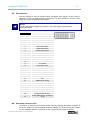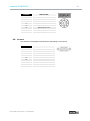
1
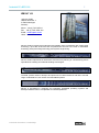
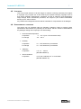
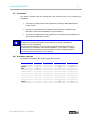
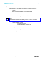
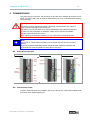
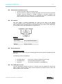
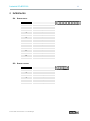
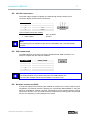
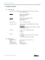
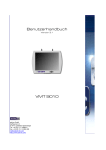
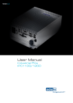
User Manual Industrial PCs BPC1000 Industrial PCs BPC1000 2 Product Portfolio Copyright ads-tec GmbH Heinrich-Hertz-Str. 1 D-72622 Nürtingen Germany © ads-tec GmbH • Heinrich-Hertz-Str. 1 • D-72622 Nürtingen Industrial PCs BPC1000 3 INDEX About us ...................................................................................................................................... 5 1 Remarks ..................................................................................................................... 6 1.1 1.2 1.3 1.4 1.5 1.6 1.7 1.8 1.9 Relevant device documentation ............................................................................................... 6 Description of the warning symbols used in this guide ........................................................ 6 Data, Images, Amendments and Variations ............................................................................ 6 Trademarks................................................................................................................................. 6 Copyright .................................................................................................................................... 7 Environmental conditions ......................................................................................................... 7 Standards ................................................................................................................................... 8 Equipment versions .................................................................................................................. 8 Scope of delivery ....................................................................................................................... 9 2 Operating instructions ............................................................................................ 10 2.1 2.1 2.2 2.3 2.4 Operating location ................................................................................................................... 10 Damages due to Improper Use ............................................................................................... 10 Warranty / Repairs ................................................................................................................... 11 Handling and proper disposal of lithium batteries ............................................................... 11 Safety Instructions .................................................................................................................. 11 3 Installation ............................................................................................................... 12 3.1 3.2 Layout for device installation ................................................................................................. 12 Order of installation ................................................................................................................. 13 4 Commissioning ....................................................................................................... 14 4.1 4.2 4.3 4.4 4.5 4.6 Available interfaces ................................................................................................................. 14 Cable installation ..................................................................................................................... 14 Operational readiness check .................................................................................................. 15 PLC switch................................................................................................................................ 15 Status displays......................................................................................................................... 15 PLC LED (two colors) .............................................................................................................. 15 5 Interfaces ................................................................................................................. 16 5.1 5.2 5.3 5.4 5.5 5.6 5.7 5.8 5.9 Digital input .............................................................................................................................. 16 Digital output ............................................................................................................................ 16 24 V DC power supply ............................................................................................................. 17 USB connections ..................................................................................................................... 17 Network connection (RJ45) .................................................................................................... 17 COM port................................................................................................................................... 18 DVI Interface ............................................................................................................................. 19 Switching the resolution ......................................................................................................... 19 Interbus ..................................................................................................................................... 20 © ads-tec GmbH • Heinrich-Hertz-Str. 1 • D-72622 Nürtingen Industrial PCs BPC1000 4 6 Software & driver installation ................................................................................. 21 6.1 6.2 Installing the operating system ............................................................................................. 21 Lock USB function .................................................................................................................. 22 7 Technical details ..................................................................................................... 23 7.1 7.2 Computer data ......................................................................................................................... 23 General data............................................................................................................................. 23 8 Service and Support ............................................................................................... 24 8.1 8.2 ads-tec Support ....................................................................................................................... 24 Company Address .................................................................................................................. 24 © ads-tec GmbH • Heinrich-Hertz-Str. 1 • D-72622 Nürtingen Industrial PCs BPC1000 5 ABOUT US ads-tec GmbH Heinrich-Hertz-Str. 1 D-72622 Nürtingen Germany Phone: +49 (0) 7022 2522-0 Fax: +49 (0) 7022 2522-400 E-Mail: [email protected] Home: www.ads-tec.com ads-tec GmbH provides large enterprises and globally active corporations with cutting edge technology, up-to-date know-how and comprehensive services in the area of automation technology, data processing technology and systems engineering. ads-tec GmbH implements full automation solutions from planning to commissioning and is specialized in handling and material handling technologies. The data systems division develops and produces PC based solutions and offers a broad range of industrial PCs, thin clients and embedded systems. ads-tec is specialized in modifying and optimizing embedded operating systems and develops software tools to complement its hardware platforms. © ads-tec GmbH • Heinrich-Hertz-Str. 1 • D-72622 Nürtingen Industrial PCs BPC1000 6 1 REMARKS 1.1 RELEVANT DEVICE DOCUMENTATION Consult the following documentation for information pertaining to device setup and operation: USER MANUAL ON THE SERVICE CD (THIS DOCUMENTATION): Contains information pertaining to device mounting, startup and operation as well as the technical data for the device hardware. SERVICE CD: Contains drivers, user manual and installation instructions for installing drivers. a 1.2 DESCRIPTION OF THE WARNING SYMBOLS USED IN THIS GUIDE Warning: The “Warning” symbol precedes warnings on uses or operations that might either lead to personal injury and/or hazards, or to any hardware and software damages. Note: This Symbol indicates special notes, terms and/or conditions that strictly need to be observed to ensure optimised and/or zero-defect operations. It also precedes tips and suggestions for efficient unit implementation and software optimisation. 1.3 DATA, IMAGES, AMENDMENTS AND VARIATIONS The texts, data and images herein are not binding. The right to any subsequent amendment and/or variation due to any technical and engineering progresses in the art whatsoever is hereby reserved. 1.4 TRADEMARKS It is hereby notified that any software and/or hardware trademarks further to any company brand names as mentioned in this User’s Guide are all strictly subject to the various trademark, brand name and patent protection rights. ® ® ® WINDOWS , WINDOWS CE and WINDOWS CE.net™ are registered trademarks of Microsoft Corp. ® ® Citrix and ICA are registered trademarks of Citrix Systems Inc. ® ® Intel and Pentium are registered trademarks of Intel Corp. ® ® ® IBM , PS/2 and VGA are registered trademarks of IBM Corp. CompactFlash™ and CF™ are registered trademarks of SanDisk Corp. Any further additional trademarks and/or brand names herein, be they domestic or international, are hereby duly acknowledged. © ads-tec GmbH • Heinrich-Hertz-Str. 1 • D-72622 Nürtingen Industrial PCs BPC1000 1.5 7 COPYRIGHT This User’s Guide inclusive of all the images it contains is entirely proprietary and subject to copyright. Any irregular use of this Guide by third parties infringing copyright terms is thus strictly forbidden. Reproduction, translation, as well as electronic and photographic image storage and/or amendment processes, are subject to prior written authorisation directly by M/s. ads-tec GmbH. Any violation and infringement thereto will be held liable for compensation of all damages. 1.6 ENVIRONMENTAL CONDITIONS The device may be operated under the following conditions. Failure to observe these specifications will terminate any warranty for this device. Ads-tec cannot be held liable for any damages arising due to improper use and handling. Environmental temperature In operation 0 … 55° C (incl. CF and without HDD) For storage -20 … 60° C Humidity In operation For storage Vibrations In operation Shock resistance In operation © ads-tec GmbH • Heinrich-Hertz-Str. 1 • D-72622 Nürtingen 10 … 85% without any condensate 10 … 85% without any condensate 1 G, 10 … 150 Hz (DIN EN 60068-2-6) 15 G, with a half-wave of 11 ms duration (DIN EN 60068-2-27) Industrial PCs BPC1000 1.7 8 STANDARDS This device complies with the requirements and protective aims of the following EC regulations: This device complies with the test regulations according to EN 60950 and EN 6100-6-4:2001 The device also meets the test regulation requirements in accordance with EN61000-6-2:2001 and EN 60068-2-6 (sinus excitation) This device complies with the test regulations in accordance with EN 60068-2-27 (shock test) and EN 55011, class A Note: A respective conformity declaration for the authority in charge is available on request from the manufacturer. All connected components, as well as cable connections must also meet these requirements for compliance with the EMC legislation. For this reason, screened bus and LAN cables including screened connectors must be used and installed according to the instructions in this user manual. 1.8 EQUIPMENT VERSIONS The system is available in the following equipment versions: BPC 1000 PC version ZEPHE version Interbus version Sercos version X X X X Interbus X As an option NVRAM As an option As an option Compact Flash memory HDD ZEPHE module I/O X X Sercos Run / stop switch © ads-tec GmbH • Heinrich-Hertz-Str. 1 • D-72622 Nürtingen X X X Industrial PCs BPC1000 1.9 SCOPE OF DELIVERY Please check that all of the following components are contained in the packaging: 1 x device Service CD including manual and drivers for Windows XP® 1 x 3-pin COMBICON connector Vendor: Phoenix Contact Part designation: MC 1,5 / 3-STF-3,81-BD Note: The COMBICON connectors in the following list are only included in the scope of delivery with the equipment version including I/Os. 1 x 6-pin COMBICON connector Vendor: Phoenix Contact Part designation: MCVR 1,5 / 6-STV-3,81 1 x 14-pin COMBICON connector Vendor: Phoenix Contact Part designation: MCVR 1,5 / 14-STV-3,81 Wall bracket (pre-installed) © ads-tec GmbH • Heinrich-Hertz-Str. 1 • D-72622 Nürtingen 9 Industrial PCs BPC1000 10 2 OPERATING INSTRUCTIONS This device contains electrical voltages and extremely sensitive components. User intervention is restricted to plugging in additional cards, only. The manufacturer or a service partner authorised by the manufacturer should be consulted if you plan to make further modifications. For this type of work, the device must be switched off at the mains and the power lead must be disconnected. Suitable measures for avoiding electrostatic discharge towards parts of the components when touching the equipment must be taken. If the device is opened by an unauthorised person, hazards for the user might arise and any warranty claim will cease. General instructions: All users must read this manual and have access to it at all times. Installation, commissioning and operation may only be carried out by trained and qualified staff. The security instructions and the manual itself must be observed by all persons who work with this device. At the location of use the valid guidelines and regulations for accident prevention must be observed. The manual contains the most important instructions on how to use this device in a safe way. Appropriate storage, proper transport, installation and commissioning, as well as careful operation are prerequisites for ensuring safe and proper operation of the device. Warning: Any leads (e.g. power leads, interface cables) may only be connected if the device is switched off in order to avoid damaging the device. 2.1 OPERATING LOCATION The control system is designed for use inside a switching cabinet. You must ensure compliance with the specified environmental conditions. Using the device in non-specified environments, like e.g. onboard of ships, in areas that might contain explosive gases or in extreme heights is prohibited. Warning: The device may only be switched on after acclimatising to the ambient temperature in order to avoid condensate accumulation. The same applies if the device has previously been exposed to extreme temperature variations. To avoid overheating: The device must not be exposed to direct radiation by sunlight or any other light or heat source. If the device is integrated in a panel, casing or similar enclosures, you must ensure that no heat accumulation builds up. The maximum permissible environmental temperature must never be exceeded. 2.1 DAMAGES DUE TO IMPROPER USE Should the service system have evident signs of damages incurred e.g. due to wrong operation or storage conditions or due to improper unit use, the unit must be decommissioned or scrapped. Ensure that it is safe from accidental re-implementation. © ads-tec GmbH • Heinrich-Hertz-Str. 1 • D-72622 Nürtingen Industrial PCs BPC1000 2.2 11 WARRANTY / REPAIRS During the unit warranty period, any repairs thereto must strictly be conducted solely by the manufacturer or by service personnel that has been duly authorised by the manufacturer. 2.3 HANDLING AND PROPER DISPOSAL OF LITHIUM BATTERIES Caution: Danger of explosion and the release of toxic substances Lithium batteries should not be exposed to fire, soldered, recharged, opened, shortcircuited, reversed or heated above 100 °C and they should be disposed of properly as well as protected against sunlight, moisture and condensation. The lithium battery can only be replaced by the same type or a type recommended by the manufacturer. The used lithium battery should be disposed of in accordance with local legal regulations. 2.4 SAFETY INSTRUCTIONS Warning: All unit assembly operations must be strictly conducted only under safe, secure and zero-potential conditions. Special Note: When handling parts and components susceptible to electrical discharge, please accurately observe all the relevant safety provisions. (DIN EN 61340-5-1 / DIN EN 61340-5-2 refers) © ads-tec GmbH • Heinrich-Hertz-Str. 1 • D-72622 Nürtingen Industrial PCs BPC1000 3 INSTALLATION 3.1 LAYOUT FOR DEVICE INSTALLATION © ads-tec GmbH • Heinrich-Hertz-Str. 1 • D-72622 Nürtingen 12 Industrial PCs BPC1000 3.2 13 ORDER OF INSTALLATION The BPC 1000 device may be installed by using the pre-installed wall-mount bracket. The wall-mount bracket allows installing the device on a wall or inside a switching cabinet. The BPC 1000 installation at the intended location can be carried out by using both holes at the upper and lower edge of the wall-mount bracket. Dimensions and distances may be determined in detail from the figure. © ads-tec GmbH • Heinrich-Hertz-Str. 1 • D-72622 Nürtingen Industrial PCs BPC1000 14 4 COMMISSIONING The power supply connection and interfaces of this device are installed at the device front panel. All supply leads and all required data leads have to be connected before starting commissioning. Warning: The device must be switched off before connecting or disconnecting any cables in order to prevent damage to the electronics! The device may only be switched on after acclimatising to the ambient temperature in order to avoid condensate accumulation. Make sure to meet the permissible voltage requirements for this device. After switching off and before switching on you must wait for at least 5 seconds. Note: The screen of a data cable must always be connected with the connector housing (EMC). Under the embedded operating system, interfaces must explicitly be enabled and required drivers must be installed for being able to use them. 4.1 AVAILABLE INTERFACES PC VERSION 4.2 INTERBUS VERSION SERCOS VERSION CABLE INSTALLATION The BPC 1000 interfaces are installed in the front of the device. Install required data leads and secure them against slipping out. © ads-tec GmbH • Heinrich-Hertz-Str. 1 • D-72622 Nürtingen Industrial PCs BPC1000 4.3 4.4 15 OPERATIONAL READINESS CHECK Connect the power cable to the power source. Check the device to determine whether damages have been caused by improper transport, incorrect operation or storage conditions or improper handling (e.g. smoke emission from the device, etc.). If damages are found, immediately shut down the device and protect it against unintentional startup. PLC SWITCH The PLC switch is located underneath the cover at the front of the device. The PLC software can be controlled by using the PLC switch. The function of individual switch positions may vary depending on the software and PLC version used. Additionally, you can read current status information by using the keys. EXAMPLE: SWITCH POSITION 4.5 DESCRIPTION RUN / PROG: Run or programming status STOP: PLC is stopped MRESET: The PLC is reset STATUS DISPLAYS SYS LED (BICOLOURED) Depending on the colour and type of flashing different device states are displayed by the SYS LED. The following signals are displayed: 4.6 LED lights green The device is ready for operation (Power ON). LED flashes red Environmental temperature too high. LED is off The device is switched off. (POWER OFF) PLC LED (TWO COLORS) This LED indicates the status of a soft PLC. A soft PLC has to be installed in order for this LED to display various signals. Various device statuses are indicated by the colors and flashing patterns of the PLC LED. © ads-tec GmbH • Heinrich-Hertz-Str. 1 • D-72622 Nürtingen Industrial PCs BPC1000 16 5 INTERFACES 5.1 5.2 DIGITAL INPUT PIN NUMBER SIGNAL NAME 1 24V DC 2 GND 3 Input 1 4 Input 2 5 Input 3 6 Input 4 7 Input 5 8 Input 6 9 Input 7 10 Input 8 11 Input 9 12 Input 10 13 Input 11 14 Input 12 DIGITAL OUTPUT PIN NUMBER SIGNAL NAME 1 24V DC 2 GND 3 Output 1 4 Output 2 5 Output 3 6 Output 4 © ads-tec GmbH • Heinrich-Hertz-Str. 1 • D-72622 Nürtingen Industrial PCs BPC1000 5.3 17 24 V DC POWER SUPPLY The power supply voltage is supplied via a feed-through clamp including screw connection (figure shows socket in the device). PIN NUMBER SIGNAL NAME 1 24V DC 2 PE 3 0 VDC Technical data of the power adapter Power consumption: Max. 60 Watts Input voltage: 24V DC Note: The typical power consumption of this device is indicated in the "Technical details" chapter. 5.4 USB CONNECTIONS The USB interfaces are used for connecting peripherals with USB connection. The interface complies with the USB 2.0 standard. PIN NUMBER SIGNAL NAME 1 VDC 2 D- 3 D+ 4 GND Note: The USB interfaces may be locked using the Lock USB software tool. You'll find the software and the documentation on the service CD. 5.5 NETWORK CONNECTION (RJ45) If the drivers required for functioning are installed on the device, the control system may be integrated in an Ethernet network supporting the 10/100/1000 Mbit standard by using the Ethernet 10/100BaseT network connector. Specifications of this network topology must be observed in this case. You can install the drivers required for functioning from the enclosed service CD, should they not be installed on the device. © ads-tec GmbH • Heinrich-Hertz-Str. 1 • D-72622 Nürtingen Industrial PCs BPC1000 5.6 18 COM PORT The mini-DIN interface in the device is used as a COM port. PIN NUMBER SIGNAL NAME 1 Data 2 NC 3 GND 4 +5V 5 Clock 6 NC © ads-tec GmbH • Heinrich-Hertz-Str. 1 • D-72622 Nürtingen Industrial PCs BPC1000 5.7 19 DVI INTERFACE The DVI Interface is used to transfer analog and digital video signals. A DVI-I Cable is required to connect a digital display to the device. It is also possible to connect a VGA display by using a suitable DVI-VGA adapter. Notice: The DVI Interface is a Single Link Interface. The video signals are transferred analog and digital. 5.8 PIN-NUMMER SIGNAL NAME 1 TMDS Data2- 2 TMDS Data2+ 3 TMDS Data2/4 Shield 4 N/C 5 N/C 6 DDC Clock [SCL] 7 DDC Data [SDA] 8 Analog vertical sync 9 TMDS Data1- 10 TMDS Data1+ 11 TMDS Data1/3 Shield 12 N/C 13 N/C 14 +5V Power 15 Ground (for +5V) 16 Hot Plug Detect 17 TMDS Data0- 18 TMDS Data0+ 19 TMDS Data0/5 Shield 20 N/C 21 N/C 22 TMDS Clock Shield 23 TMDS Clock+ 24 TMDS Clock- C1 Analog Red C2 Analog Green C3 Analog Blue C4 Analog Horizontal Sync C5 Analog GND Return: (analog R, G, B) SWITCHING THE RESOLUTION The feature of switching the resolution allows manually changing the display resolution at the device. Stages 0-2 are the predefined default settings you can find in the table. Stages 3-7 are undefined defaults. A resolution of 800 x 600 is used for output by default. © ads-tec GmbH • Heinrich-Hertz-Str. 1 • D-72622 Nürtingen Industrial PCs BPC1000 5.9 20 NUMBER RESOLUTION 0 800 x 600 1 1024 x 768 2 1280 x 1024 3 [DEFAULT] 800 x 600 4 [DEFAULT] 800 x 600 5 [DEFAULT] 800 x 600 6 [DEFAULT] 800 x 600 7 [DEFAULT] 800 x 600 INTERBUS This interface is integrated inside the device depending on the version. PIN NUMBER SIGNAL NAME 1 DOH 2 DIH 3 GNDi 4 GND 5 Vcci 6 DOL 7 DIL 8 Vcc 9 Not connected If Windows C E.net or Wi ndows XPe is us ed, the entir e operating s ys tem may be c ompletel y i nstalled from the U SB stic k usi ng the res pecti ve i mage. The r equired i mage c an be purchas ed from the ads-tec c ompany or vi a the ASSIX online portal . © ads-tec GmbH • Heinrich-Hertz-Str. 1 • D-72622 Nürtingen Industrial PCs BPC1000 21 6 SOFTWARE & DRIVER INSTALLATION The device will be delivered with a pre-installed Windows operating system on request by the customer. The drivers required for this, are already installed and the operating system will be enabled by entering the licence information. Should an initial installation be required, please follow the following steps. With a later operating system like Windows XP, the network card and graphics card will properly be recognised during the initial installation, so that only additional hardware cards must separately be installed. Note: If the hard drive was formatted, the installation can be carried out by using the internal drives, the USB interface or the network connection. An external keyboard is required for installation. 6.1 INSTALLING THE OPERATING SYSTEM If the device is not equipped with an integrated drive, installing the operating system can only be carried out by using either a network connection or the USB interface. In order to perform the installation by using the network, the device must be able to access the CDROM drive of another PC. Procedure for installation: Network: Create a bootable DOS drive with access to the user-specific network. Boot the device by using the DOS drive and install a boot partition on the hard disk. Copy the i386 folder from the CD-ROM to the hard drive of the device. Copy drivers from the supplied CD-ROMs to the hard drive of the device. USB: The boot drive in the system Bios must be switched to USB in order to boot the device from the USB interface. Restart the device and insert the Windows CD. Install the required software and/or the required drivers. If Windows CE.net or Windows XPe is used, the entire operating system may be completely installed from the USB stick using the respective image. L © ads-tec GmbH • Heinrich-Hertz-Str. 1 • D-72622 Nürtingen Industrial PCs BPC1000 6.2 22 LOCK USB FUNCTION FUNCTIONAL SCOPE: The Lock USB function allows locking of USB ports. If the lock is switched on, the USB ports will be disabled by the operating system. Connected devices will not be recognised. SYSTEM REQUIREMENTS: The Lock USB function requires the Windows XP® or Windows XP embedded® operating system as a prerequisite. INSTALLATION Note: This tool and the related documentation is included on the supplied service CD. © ads-tec GmbH • Heinrich-Hertz-Str. 1 • D-72622 Nürtingen Industrial PCs BPC1000 23 7 TECHNICAL DETAILS 7.1 COMPUTER DATA The device may be equipped with the following ads X modules ex factory (according to customer requirements) 7.2 VERSION 1 INTEL Celeron M 800 MHz ULV 256MB - 2GB DDR RAM Intel 855 GME VERSION 2 INTEL Pentium M 1.4 GHz 2MB Cache 256MB - 2GB DDR RAM Intel 855 GME Graphic memory A max. of 32 MB shared memory Mass storage device 1 x compact flash device, 256MB-2GB under front cover, external access AS AN OPTION: 2.5" HDD incl. at least 60GB of internal storage / 1 x ZEPHE module with 1GB - 4GB Interfaces: 1 x COM 1 (on a mini RS232 DIN socket), 1 x DVI-I 3 x USB 2.0 Network 3 x Ethernet: 1 x controller 82551QM switched on 2 RJ45 connectors (10/100 Mbit) 1 x controller 82541ER (10/100/1000Mbit) GENERAL DATA External dimensions Weight Protection class Power consumption Max. switch-on current © ads-tec GmbH • Heinrich-Hertz-Str. 1 • D-72622 Nürtingen 72 mm x 240 mm x 174 mm (W x H x D) approx. 2.3 kg IP 20 60 Watts (typical) 2.5 Amperes (for 2ms) Industrial PCs BPC1000 24 8 SERVICE AND SUPPORT ads-tec and appointed partner companies offer you comprehensive maintenance and support services, ensuring quick and competent support should you have any questions or concerns with regard to ads-tec products and equipment. ads-tec products may also be provided and installed by partner companies. Such devices may have customised configurations. Should any questions arise with regard to such specific settings and software installations, please contact the system supplier in question as ads-tec will not be able to reply to such questions. ads-tec does not provide support services for any device or unit that was not bought directly from ads-tec. In any such case, maintenance and support is provided solely by the partner company that supplied the device or unit. 8.1 ADS-TEC SUPPORT Das Support Team von ads-tec steht für Direktkunden von Montag bis Freitag von 8:30 bis 17:00 unter der unten genannten Telefonnummer zur Verfügung: Tel: +49 7022 2522-202 Fax: +49 7022 2522-2602 E-Mail: [email protected] 8.2 COMPANY ADDRESS ads-tec GmbH Heinrich-Hertz-Str.1 72622 Nürtingen Germany Tel: +49 7022 2522-0 Fax: +49 7022 2522-400 E-Mail: [email protected] Home: www.ads-tec.de © ads-tec GmbH • Heinrich-Hertz-Str. 1 • D-72622 Nürtingen