1
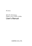
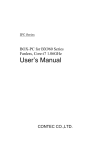
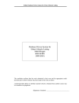
PLC temporary lock User Manual Author: Franz Stelzer Version: 1.0 Date: 03/24/09 preliminary 1 Contents 0. Introduction ……………………………………………... 3 1. PLC Init ………………………………………………………… 4 2. PLC Main screen …………………………………………….. 4 …………………………………………….. 3.1. Main screen – Detector Movement ………………………... 3.2. Shutter menu ………………………………. 3.3. Choose Motor ………………………………. 3.4. Control Motor ………………………………. 3.5. The motor programs ………………………………. 3.5.1. Homing ………………………………. 3.5.2. Release down ………………………………. 3.5.3. Motor program 1301 ………………………………. 3.5.4. Motor program 1302 ………………………………. 3.5.5. Motor program 1303 ………………………………. 3.5.6. Motor program 1304 ………………………………. 3.5.7. Motor program 1305 ………………………………. 3.5.8. Motor program 1306 ………………………………. 3.5.9. Motor program 1307 ………………………………. 3.5.10. Motor program 1308 ………………………………. 3.5.11. Motor program 1309 ………………………………. 3.5.12. Motor program 1310 ………………………………. 3.5.13. Jog up / down ………………………………. 6 6 7 9 10 12 13 15 16 16 17 18 18 18 18 19 19 19 19 3. Move Detectors 2 0. Introduction The PLC system of the commissioning lock is responsible for 1. Status control of lock system parameters (pressures, shutter positions, etc.) 2. Movement of the string motors 3. Interlocks Furthermore it is through the PLC box that most of the shutters and the pumps are being operated. Note that some of the functionality is not available for the Hall di Montaggio setup. Fig. 1 shows a picture of the PLC box with its components. Fig 0.1...The PLC box with. 3 1 Switching on the PLC - PLC Init The PLC can be switched on by …. As soon as the PLC is switched on, it first performs an initialization. During this initialization process, global and local PLC software variables are defined and the number of accessible motor controllers is diagnosed and initialized. Thus default values like motor acceleration/deceleration and motor current are written into each motor controller. The last stored positions of the detector strings are also loaded. The progress of the initialization is shown in progress bars (see Fig. 1.1). When the initialization process is finished the system automatically switches to the PLC Main screen which is shown in the next section. The PLC is now set into standby mode. Fig. 1.1. The PLC Init Screen. 4 2. The PLC Main screen The whole functionality of the PLC is accessible through the PLC main screen which is given in figure 2.1. The following optyions can be chosen: 0. PLC Init: Initialization (see 1.) 1. Maintenance: Interlocks are switched off. CAUTION: Operation of the system possible without control of system parameters! 2. Move detectors allows for moving the strings. 3. Setup: Adjustment of critical system parameters. 4. Measurement Certain menus are only available for certain user groups. Table 2.1 gives an overview of the functions which can be executed by the different user groups. The function 'emergency stop' can be executed by all user groups at any time. All menus are password protected. Depending on the user group, certain actions can be executed. User Operator Maintenance Administrator Functions PLC Init measurement move detectors Maintenance setup Table 2.1 Certain PLC functions are only available for certain user groups In all submenus described in the following chapter the “arrow up” button in the center bottom brings the user back the next higher level. If functions can be executed in a submenu, the chosen function names are displayed in the white bar in the bottom of the screen. The function to be executed can be chosen by the “arrow up” and “arrow down” buttons in the bottom right corner of the screen. 5 Fig 2.1 The PLC Main screen contains all functions of the PLC 3. Move Detectors 3.1. Main screen – Detector Movement To access the main screen for detector movement, you must click on the 'move detectors' button. The main move detector screen is shown in figure 3.1. It displays all relevant information required to move detectors and to enable shutter movement. The display shows the position of the shutters (open /close) and illustrates the position of the strings with blue bars. A high voltage sign also appears when high voltage can be applied to the detectors (Measurement going on). At the lower right corner there are four menu buttons. Table 3.1. gives an overview about their functions. 6 Fig 3.1. The Main screen – Detector Movement. Button Arrow up Shutters Choose motors Control motors Function Comment Back to PLC Main screen Enable/ disable shutters For details refer to section 3.2 Select a motor For details refer to section 3.3 Select a motor program and move a string For details refer to section 3.4 Table 3.1. Overview of the menu buttons on the Main screen – Detector movement 3.2. Shutter menu Depending on your state of operation, you may be able to open and close shutters using the shutter menu. On the shutter menu, the absolute pressure (1) inside the cable arms, the absolute pressure in the pump flange (2) and the 7 differential pressure (3) between cryostat and cable arms are displayed. On the lower left side there are arrow up/ down buttons (4) where you can browse the menu. Table 3.2 gives an overview of the contents of this menu. No. 1 2 3 4 5 Program Enable 250 shutter Enable 160 shutter Enable pump 250 shutter Enable pump 160 shutter Back to main menu Table 3.2 Overview of the functions inside the shutter menu There is also a 'start' button (5), a 'stop' button (6) and an 'arrow up' (7) button. To select a shutter use the arrow up/ down buttons (4) to find the shutter you want to enable. Then press the start button (5). The PLC then enables this shutter and you should now be able to see the 'shutter-enabled' light glowing in the front of the cabinet. The selected shutter will also be marked as 'enabled' on the PLC screen. Depending on which shutter menu you selected first, press the “open shutter” or “close shutter” button on the PLC cabinet to move the shutter. Like any other PLC operation, these are monitored by the state machine of the PLC since forbidden operations could cause serious damage to the lock. Only maintenance and administrator personnel have permission to move the cryo shutter. The shutter screen is shown in figure 3.2. 8 Fig 3.2 The shutter menu 3.3. Choose Motor On the 'Choose Motor' screen you can select the string which you want to move. By tipping into the left or right string selector (1) the corresponding motor will be activated and the inner circle (2) on the screen will turn blue. The present position of the selected string is shown in the current position display (4) on the left hand side of the screen. To undo your selection press reset choice (3) and make your new selection. Values that are shown in “target”, “wait” or “pre” can be ignored at this stage. To move the selected string press the 'arrow up' button (5) on the lower left hand side to return to the main screen. Then select the 'control motors' button which will lead you to the Control Motor Screen, described in the following section. 9 Fig 3.3. The Choose Motor Screen. Only one cable arm can be selected 3.4 Control Motors The Control Motor screen is very similar to the Choose Motor screen and is shown in the figure 3.4. With the arrow up/down buttons (11) you can scroll through the main menu, enable the motor controller and select the program you want to run. Table 3.3. gives an overview of the functions and programs available in the main menu (10). To run a motor or a motor program, the motor controller has to be enabled first. Select the program “Enable Motor Controller” with the arrow up/down buttons (11) and press the start button (12). The motor that was selected as described in section 3.3 is now enabled. The outer circle of the string selector (2) ( see fig. 3.3 ) will then turn blue as well. Now a motor program can be selected. As soon as a motor program is selected, its precondition, wait time and target of the appropriate motor program is displayed in the corresponding fields (2), (3), (5). These display fields will be described in more detail in the following sections. After you have selected a motor program, press the start button (12) to run the motor. 10 1 2 8 3 4 5 9 6 10 11 12 Fig 3.4 The Control Motor Screen allows you to select different motor programs to immerge detectors into liquid argon or take them out of the cryostat No . -- Program Enable Motor controller --1301 1302 1303 1304 1305 1306 1307 1308 1309 Homing Release Down +150 – GoTo mt RailSys -130 – Auto – (un)mt String +20 – GoTo – unmt RailSys -150 – GoTo – parking position +900 – Auto – immerge string LAr -6000 – GoTo – parking position +900 – GoTo – immerge string mb +150 – GoTo – parking position +900 – GoTo – mt RailSys 1310 1311 1312 -150 – GoTo – standby Function Comment Enables the selected motor controller Defines the zero position of the PLC Releases the string after homing Mount temporary rail system Mount string Unmount temporary rail system Swivel in bulk tube Immerges the string into LAr Swivel out bulk tube Immerges the string in methanol bath Take out string of bath Mount temp. rail system after warmup of the detector 0 See section 3.5.1 See section 3.5.2 See section 3.5.3 See section 3.5.4 See section 3.5.5 See section 3.5.6 See section 3.5.7 See section 3.5.8 See section 3.5.9 See section 3.5.10 See section 3.5.11 11 Table 3.3. Overview of the functions and motor programs The outer circle in the string selector display will change from light to dark blue until the target position is reached. The current position of the string is displayed in the position display (1) and the arrow (8) indicates the direction of the movement of the string. As soon as the target position is reached the outer circle of the string selector and the arrow (8) will stop blinking. In the following sections the motor programs and their usage are explained in detail. IMPORTANT: The automatic button (4) in Fig. 3.4 ensures that the sequence of motor movements defined in a motor program is carried out without interruption. If this button is not activated, the PLC stops after the first sequence. The motor program will NOT CONTINUE! In this case a different motor program has to be chosen with the preset value identical to the real value! In case the position of the motor is at a position which does not coincide with any precondition of the desired motor program use the Jog up / down programs, which are discribed in section 3.5.13. 3.5 The motor programs In principle all motor programs have a syntax which consists of the present position of the string (precondition to execute this program) and the task that you desire to do. The following figure 3.5. gives an example of how the motor programs appear in the main menu (10). Fig 3.5. The syntax of the motor program. As soon as the current position [mm] (also displayed in the precondition display (2)) matches with the position display (1), the selected motor program 12 is executable. Otherwise the start command will be ignored. Figure 3.6. is a screenshot of the PLC screen and gives another example how the programs have to be used. In this screenshot the matrix plate is at position +150.00 mm and should be lowered to mount the temporary rail system. If the motor program 1301 is now selected using (11), since the precondition of this motor program (2) matches the live position (1) of the matrix plate the program can be executed. The selected motor program is shown in (10). The position of the matrix plate after the execution of the motor program is shown in the target display field (5). Fig 3.6. In this example the matrix plate is at +150.00 mm and should be lowered to mount the temporary rail system to insert a string. 3.5.1 Homing It is important to understand that the PLC has its own coordinate system (shown in Fig. 3.7.) which is independent from that of the GERDA experiment. To define the zero position of the PLC there is a motor program called “Homing”. Tests have shown that as soon as the zero position of the 13 PLC is defined the precision of the motors keeps the zero position for quite some time and depending on the usage of the PLC, “Homing” only needs to be performed rarely. It is usually a task of the maintenance personnel, although the operator also has the opportunity to execute this program. For “Homing”, the temporary rail system has to be mounted and the matrix plate should already be close underneath the rail system, since “Homing” is a process that causes some mechanical stress to the whole system. For this reason the velocity of the movement of the matrix plate is set to be very slow. To perform “Homing” select the accordant motor program with the arrow up/down – buttons (11) and press 'start' (12). Figure 3.8 shows the setup required to perform “Homing”. Fig 3.7. The coordinate system of the PLC. When the string is above the 0level, position values are shown with a positive sign (and if below the 0-level, then values are given with a negative sign). 14 Fig 3.8. To perform “Homing” the temporary rail system has to be mounted already. As soon as the copper bar of the matrix plate is blocked by the temporary rail system, the current of the motor increases steadily. Once the current reaches a certain threshold the motor is switched off and the coordinate of the matrix plate is set to 0.00 mm. The zero-position of the PLC is then defined. Values that are shown in “pre”, “wait” or “target” can be ignored. 3.5.2 Release Down To dismount the temporary rail system after “Homing”, select the “Release Down” – motor program with the arrow up/down – buttons (11) and press 'start' (12). This will bring the matrix plate down to -150.00 mm. After the rail system is dismounted select the motor program “1308 -150 – GoTo – Standby” to bring back the matrix plate back to it’s default position. In the following sections the motor programs are explained in detail and show when they can be used. The immersion and removal of a string from the LAr environment is described. It is assumed that there is no string attached to the 15 matrix plate and that the matrix plate is at its “standby-position” at +150.00 mm. 3.5.3 Motor program 1301 The motor program “1301 +150 – GoTo – mt RailSys” is used to release the matrix plate from +150.00 mm to -130.00 mm. This gives the operator the opportunity to mount the temporary rail system. The whole scenario is shown in figure 3.9 Fig. 3.9 The motor program 1301 brings the matrix plate to -130.00 mm so the temporary rail system can be mounted. 3.5.4 Motor program 1302 The motor program “1302 -130 – Auto – (un)mt String” is used to move the matrix plate from -130.00 mm to the temporary rail system such that the detector string can be mounted. It consists of a sequence of movements to assure safe operation. The following table 3.4 shows the sequence followed by the motor. 16 No. Movement from… to…. velocity wait time 1 2 3 -130.00 to -70.00 mm -70.00 to -10.00 mm -10.00 to +20.00 mm 500 mm/min 100 mm/min 20 mm/min 0.1 min 0 min 0 min Table 3.4 The motor program 1302 consists of a sequence of movements. Each movement is performed with a different velocity such that the approach of the matrix plate to the rail system can be easily supervised by the operator. To simplify the usage of this program, the control motor screen features an 'automatic' button (4) (see fig 3.4). As soon as you have selected the motor program 1302, press the 'start' button and then press the 'automatic' button. This causes sequence 1-3 as shown in table 3.3 to be executed automatically. This then gives the operator the opportunity to control the movement of the string or matrix plate with one hand inside the glove box to ensure that the matrix plate is brought in safely. Note that the third sequence of motor program 1302 (see table 3.3) only lifts up the matrix plate to 0.00 mm since then the copper bar is blocked by the temporary rail system. The movement of the motor from 0.00 mm to +20.00 mm only serves to apply tension into the energy chain and helps to press the matrix plate slightly to the temporary rail system. 3.5.5 Motor program 1303 After the temporary rail system and the string is mounted, select the motor program “1303 +20 – GoTo – unmt Railsys” in the main menu (10), which will release the string to –150.00 mm where the temporary rail system can be removed safely. 17 3.5.6 Motor program 1304 The motor program “1304 -150 – GoTo – parking position” lifts up the string back to the parking position at +900.00 mm so that the operator can swivel in the bulk tube and pump/flush it with argon gas. 3.5.7 Motor program 1305 To insert the string into LAr, execute motor program “1305 +900 – Auto – immerge string LAr”. As you can see in the motor program's name, this is also an automised sequence of movements. Press the 'automatic' button (4) after the 'start' button in the Control Motor Screen. This causes the string to be released to the surface of the liquid argon. After some waiting time the string is then released to its final position at -6000.00 mm 3.5.8 Motor program 1306 To take out the string from LAr, the motor program “1306 -6000 – GoTo – parking position” is used. When the string has reached the parking position the operator can swivel out the bulk tube and mount the methanol bath to warm up the detector. 3.5.9 Motor program 1307 After the methanol bath is mounted, execute motor program “1307 +900 – GoTo - immerge string mb” to immerge the string into the methanol bath. 18 3.5.10 Motor program 1308 As soon as the detector string is warmed up, execute motor program “1308 +150 – GoTo – parking position” to lift up the string to the parking position and remove the methanol bath from the lock. 3.5.11 Motor program 1309 In order to remove the string from the matrix plate the temporary rail system has to be mounted first. Execute motor program “1309 +900 – GoTo – mtRailSys” to release the string to -130.00 mm and mount the temporary rail system. Subsequently execute motor program “1302 -130 – Auto – (un)mt String” and press the 'automatic' button (see section 3.6.4). As soon as the matrix plate has reached the final position of this program, unmount the string and execute motor program “1303 +20 – GoTo – unmount rail system” to allow you to unmount the temporary rail system. 3.5.12 Motor program 1310 To bring back the matrix plate to the standby position simply execute motor program “1310 -150 –GoTo – standby”. 3.5.12 Jog up / down In case the position of the motor is at a position which does not coincide with any precondition use the jog up / down programs. With these programs you can move ( upwards/downwards) the string up to 1000 mm with a moderate velocity. These programs also can be found in the main menu (10, see fig. 3.4). Select the program and press the start button (12). Now watch carefully the live values (1). As soon as the string reaches a position where the predefined motor programs can conitinue the movement press the start stop button (12) and continue with regular movement. If neccesary these programs can be executed several times if the desired travel range exeeds the 1000 mm. 19 To leave the control motor screen select the menu item “back to main menu” with the arrow up/down button (11), press the 'start' button (12) and then click the 'arrow up' button (9) (see fig. 3.4). 20