1
User manual deltaflowC
1. Welcome to systec Controls
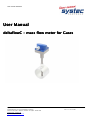
Thank you very much for using deltaflowC. deltaflowC is a state-of-the art mass flow meter for gases.
This user manual guides you through the installation and parameterization step-by-step
2. Index
1. Welcome to systec Controls ..............................................................................................................2
2. Index .................................................................................................................................................2
3. Scope of Supply / Unpacking ............................................................................................................3
4. CE / Electromagnetic compatibility ....................................................................................................3
5. Mounting ...........................................................................................................................................4
6. Recommended mounting position .....................................................................................................7
7. Wiring................................................................................................................................................8
8. Parameterization ...............................................................................................................................9
8.1. deltaflowC Designer Software ........................................................................................................9
8.2. Parameterization step-by-step .......................................................................................................9
8.3. Choose measurement span, outputs and damping ...................................................................... 13
9. Span / Accuracy .............................................................................................................................. 18
10. Specification ................................................................................................................................ 21
11. Calibration.................................................................................................................................... 22
12. Type Code ................................................................................................................................... 22
13. Maintenance ................................................................................................................................ 23
14. Further information....................................................................................................................... 23
15. Any questions? ............................................................................................................................ 23
16. Annex........................................................................................................................................... 24
Table 1 Measurement accuracies .......................................................................................................... 20
Table 2 Specification.............................................................................................................................. 21
Table 3 deltaflowC Type code................................................................................................................ 22
Table 4 Densities of various gases at standard conditions ..................................................................... 24
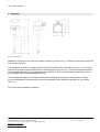
Picture 1 Dimensions ...............................................................................................................................4
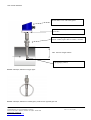
Picture 2 Example, deltaflow for bigger pipes...........................................................................................5
Picture 3 Example, deltaflow for smaller pipes, profile touches opposite pipe wall ...................................5
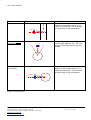
Picture 4 Straight run requirements.........................................................................................................7
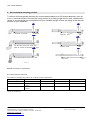
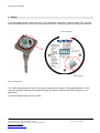
Picture 5 cable room ................................................................................................................................8
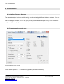
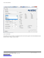
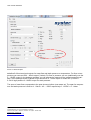
Picture 6 Selection of type of probe .........................................................................................................9
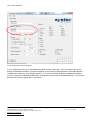
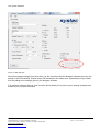
Picture 7 Select Media ........................................................................................................................... 10
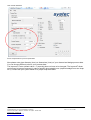
Picture 8 Selection of customized gases................................................................................................ 11
Picture 9 Eingabe Prozessparameter..................................................................................................... 12
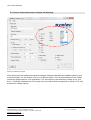
Picture 10 Choose your span ................................................................................................................. 13
Picture 11 Select signal damping ........................................................................................................... 14
Picture 12 Select Outputs ...................................................................................................................... 15
Picture 13 DIP-Switches......................................................................................................................... 16
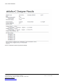
Picture 14 Example of printout of parameter settings............................................................................. 17
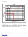
Picture 15 Estimation of span................................................................................................................. 18
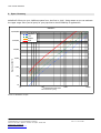
Picture 16 Example: Selection of end of span for pipe ID=200mm......................................................... 19
systec Controls GmbH
Lindberghstrasse 4, 82178 Puchheim, Germany
Telefon +49-(0)89 - 80906-0, Telefax +49-(0)89 - 80906-200
info@systec -controls.de
http://www.systec-controls.de
Seite
Rev. 1.0 27.07.2011
2