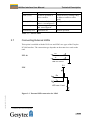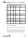
1
ISA-Bus Interface User Manual Easylon ISA-Bus Interface Easylon PC/104 Interface Gesytec GmbH Pascalstr. 6 52076 Aachen, Germany Tel. + (49) 24 08 / 9 44-0 Fax + (49) 24 08 / 94 4-100 email: [email protected] www.gesytec.com Doc. ID: 96A0016E01V3.9 Date: June 2014 ISA-Bus Interface User Manual Foreword This manual … … provides you with all the information which you will need to use the Easylon® ISA-Bus Interface and Easylon PC/104 Interface cards. However, this manual will neither explain aspects of Echelon's® LONWORKS® technology, nor Echelon's Microprocessor Interface Program (MIP), or Network Service Interface (NSI) used on theses network interface cards. The interface card network drivers have been designed in accordance with the driver specifications of the Echelon Corporation. They are not explained in detail in this manual. For further information on the LONWORKS technology please refer to the extensive documentation provided by Echelon. Especially Echelon’s “LONWORKS Host Application Programmer's Guide” will be required if applications are to be developed using Gesytec's Easylon ISA-Bus or PC/104 Interface cards as a network interface. After a general presentation of both Easylon Interface cards in Chapter 1, Chapter 2 describes the necessary steps to install the cards. Chapter 3 contains a general technical description. Archiv/96A0016E01, V3.9, June 2014 Chapter 4, "Programming Instructions", contains the information which will be of importance, should you wish to develop your own network driver software for one of the Easylon Interface cards. This documentation is subject to changes without notice. Gesytec assumes no responsibility or liability for any errors or inaccuracies that may appear in this document. Gesytec shall have no liability or responsibility to the original purchaser or any other person or entity with respect to any claim, loss, liability, or damage caused or alleged to be caused directly or indirectly by any Gesytec product or the accompanying documentation. Easylon is registered trademark of Gesytec GmbH. Echelon, LON, LONWORKS, and NEURON are registered trademarks of Echelon Corporation. Windows is a registered trademark of Microsoft. Other names may be trademarks of their respective companies. The Easylon ISA-Bus Interface card and the Easylon PC/104 Interface card incorporate the MIP/P50 or NSI programs from the Echelon Corporation. The aforesaid company holds all rights relating to this software. 2/45 ISA-Bus Interface User Manual Contents Contents 1 Product Information ..........................................................................................................5 1.1 Variants ..................................................................................................................8 1.2 Scope of Delivery.................................................................................................10 1.3 Overview ..............................................................................................................10 2 Installation ........................................................................................................................11 2.1 Setting the I/O Addresses .....................................................................................11 2.2 2.2.1 Insertion of the Card ............................................................................................12 Mounting the Ferrite Core....................................................................................12 2.3 2.3.1 2.3.1.1 2.3.1.2 2.3.1.3 2.3.1.4 2.3.2 2.3.2.1 2.3.2.2 2.3.3 2.3.4 2.3.5 2.3.6 2.3.6.1 2.3.6.2 Installation of the Network Driver .......................................................................13 Driver for Windows Operating System (WDM Drivers) .....................................13 Installation............................................................................................................13 Update ..................................................................................................................15 Parameter Setting .................................................................................................15 De-installation ......................................................................................................17 Windows 95 / NT Driver .....................................................................................17 Installation............................................................................................................17 De-installation ......................................................................................................18 EasyCheck – Test Utility for Windows Drivers ..................................................18 Windows and 16 Bit Applications .......................................................................19 Windows CE Driver.............................................................................................19 DOS Driver ..........................................................................................................20 Installation............................................................................................................20 Display of Network Drivers Installed in the Computer .......................................22 Archiv/96A0016E01, V3.9, June 2014 3 Technical Description ......................................................................................................23 3.1 Network Interface.................................................................................................23 3.2 ISA Bus Interface .................................................................................................23 3.3 Reset Procedure, System Control.........................................................................24 3.4 Block Diagram .....................................................................................................24 3.5 3.5.1 3.5.2 Connector Pin Assignments .................................................................................26 Easylon ISA-Bus Interface ...................................................................................26 Easylon PC/104 Interface .....................................................................................27 3.6 Service LED .........................................................................................................28 3.7 Connecting External LEDs ..................................................................................29 3.8 Technical Specification ........................................................................................30 3/45 ISA-Bus Interface User Manual 4 5 Contents 3.8.1 3.8.2 3.8.3 General .................................................................................................................30 Easylon ISA-Bus Interface ...................................................................................31 Easylon PC/104 Interface .....................................................................................31 3.9 Electromagnetic Compatibility ............................................................................32 Programming Instructions ..............................................................................................33 4.1 4.1.1 4.1.2 4.1.2.1 4.1.2.2 4.1.2.3 LONWORKS Network Node ..................................................................................33 Interface to the Network.......................................................................................33 Node CPU ............................................................................................................33 Coupling NEURON Chip ‹–› ISA Bus Interface ....................................................34 Interrupt Function NEURON Chip –› ISA Bus ......................................................34 NEURON Chip Address Map.................................................................................34 4.2 Device Status .......................................................................................................35 4.3 4.3.1 4.3.1.1 4.3.1.2 4.3.2 ISA Bus Interface .................................................................................................36 I/O-Address Map..................................................................................................37 Signal Assignments Control Byte ........................................................................38 Signal Assignments Status Byte ..........................................................................39 Reset Procedure ...................................................................................................39 4.4 4.4.1 4.4.2 4.4.3 4.4.4 4.4.5 4.4.6 4.4.7 Windows CE – Application Interface ..................................................................39 CreateFile .............................................................................................................39 CloseHandle .........................................................................................................40 ReadFile ...............................................................................................................40 WriteFile ..............................................................................................................40 GetVersion ...........................................................................................................41 Watcher ................................................................................................................41 ReadFile with Timeout ........................................................................................42 List of Figures ...................................................................................................................43 6 List of Tables ....................................................................................................................43 Index ..................................................................................................................................45 Archiv/96A0016E01, V3.9, June 2014 7 4/45 ISA-Bus Interface User Manual 1 Product Information Product Information Two Easylon Interfaces cards are described in this manual: Easylon ISA-Bus Interface, plug-in card for short 16 bit ISA bus slots. Easylon PC/104 Interface, ISA bus Interface card in PC/104 format. Easylon PC/104 Interface, version LP43 In this manual both cards are generally referred to as “Interface cards”. If differences between the two have to be described, they are explicitly referred to as “Easylon ISA-Bus Interface” or “Easylon PC/104 Interface”. Archiv/96A0016E01, V3.9, June 2014 NOTE: 5/45 ISA-Bus Interface User Manual G ND GESYTEC GESYTEC L PC0 x L.LOLPO… MIPEchelon Product Information VCC ST4 M1 Neuron® 3150® Chip Figure 1-1 Easylon ISA-Bus Interface (1) Service button (2) Service LED (3) Screw-plug terminal (TP/XF and FTT1 variants only) (4) 9 pin D-type connector (5) ROM with Echelon‘s MIP/P50 or NSI (6) Type identifier on rear side (see table 1.1) (7) DIP switches for setting card address (8) Connector for Watcher2 piggyback module I C11 ST1 1 2 3 4 5 6 7 8 ST2 O FF Figure 1-2 Easylon PC/104 Interface, version LP43 8 Type code: LP43.xxx 1 1 (1) Service LED 2 (2) Service button 3 (3) LON traffic LED (RX: rot, TX: grün) (4) Connector LON and shield (5) DIP switches for setting card address 7 (6) PC/104-bus connector (7) Type identifier and serial-# on connect. 6 (8) Connector for external signals 1 1 2 3 4 5 6 7 8 OFF 5 4 Figure 1-3 Easylon PC/104 Interface, version LP42 1 Type code: LP42.xxx 2 (1) Service LED 3 (2) Service button (3) LON traffic LED (optional) (4) Shield 8 (5) block terminal for LON bus (pin 1) (6) DIP switches for setting card address 7 1 (7) PC/104-bus connector 1 2 3 4 5 6 7 8 Archiv/96A0016E01, V3.9, June 2014 OFF 4 6 (8) Type identifier and serial-# on connect. 5 1 TPT = transformer coupled twisted pair, FTT = free topology transceiver 2 The Easylon Watcher has been discontinued. 6/45 ISA-Bus Interface User Manual Product Information 7 1 Gesytec LP4 2 6 Figure 1-4 Easylon PC/104 Interface, version LP4 Type code: LP4.xxx L.LOLPO… MIPEchelon (1) Service button (2) Service LED (3) 10 pin block connector 5 (4) DIP switches for setting card address (5) PC/104 connector 3 1 2 3 4 5 6 7 8 OFF Archiv/96A0016E01, V3.9, June 2014 4 (6) Type identifier on rear side (see table 1.1) (7) Connector for Watcher3 piggyback module´ 3 The Easylon Watcher has been discontinued. 7/45 ISA-Bus Interface User Manual 1.1 Product Information Variants The following variants of the Easylon Interface cards are currently available and describe in this manual. There are further, customer specific versions, to which this manual only partially applies. Each variant is identifiable by a type code sticker on the rear of the card. Type Code Order Code Network Interface Variants FTT FTT FTT FTT TP/XF-78 TP/XF-78 TP/XF-78 TP/XF-78 TP/XF-1250 TP/XF-1250 TP/XF-1250 TP/XF-1250 E/A-485 E/A-485 E/A-485 E/A-485 MIP/P50 MIP/P50 NSI NSI MIP/P50 MIP/P50 NSI NSI MIP/P50 MIP/P50 NSI NSI MIP/P50 MIP/P50 NSI NSI Easylon ISA-Bus Interface LPC.AA LPC.AB LPC.AC LPC.AD LPC.BA LPC.BB LPC.BC LPC.BD LPC.CA LPC.CB LPC.CC LPC.CD LPC.DA LPC.DB LPC.DC LPC.DD P.P10004 P.P11004 P.P10014 P.P11014 P.P10001 P.P11001 P.P10011 P.P11011 P.P10002 P.P11002 P.P10012 P.P11012 P.P10003 P.P11003 P.P10013 P.P11013 + Watcher4 + Watcher + Watcher + Watcher + Watcher + Watcher + Watcher + Watcher Archiv/96A0016E01, V3.9, June 2014 Table 1-1 Variants, order-codes and type identifiers for Easylon ISA-Bus Interface 4 The Easylon Watcher has been discontinued. 8/45 ISA-Bus Interface User Manual Type Code Order Code Product Information Network Interface Variants Version LP43 LP43.FBB P.P73106 FT-X1 MIP/P50, ext. temp., coating Version LP42 LP42.BA LP42.BC LP42.CA LP42.CC LP42.DA LP42.DC LP42.AA LP42.AC LP42.EA LP42.EC LP42.FA LP42.FC P.P10601 P.P10611 P.P10602 P.P10612 P.P10603 P.P10613 P.P10604 P.P10614 P.P10605 P.P10615 P.P10606 P.P10616 TP/XF-78 TP/XF-78 TP/XF-1250 TP/XF-1250 RS-485 RS-485 FTT10 FTT10 Direct Connect Direct Connect FTX FTX MIP/P50 NSI MIP/P50 NSI MIP/P50 NSI MIP/P50 NSI MIP/P50 NSI MIP/P50 NSI P.P10104 P.P11104 P.P10114 P.P11114 P.P10101 P.P11101 P.P10111 P.P11111 P.P10102 P.P11102 P.P10112 P.P11112 FTT FTT FTT FTT TP/XF-78 TP/XF-78 TP/XF-78 TP/XF-78 TP/XF-1250 TP/XF-1250 TP/XF-1250 TP/XF-1250 MIP/P50 MIP/P50 NSI NSI MIP/P50 MIP/P50 NSI NSI MIP/P50 MIP/P50 NSI NSI Version LP4 LP4.AA LP4.AB LP4.AC LP4.AD LP4.BA LP4.BB LP4.BC LP4.BD LP4.CA LP4.CB LP4.CC LP4.CD + Watcher5 + Watcher + Watcher + Watcher + Watcher + Watcher Archiv/96A0016E01, V3.9, June 2014 Table 1-2 Variants, order-codes and type identifiers for Easylon PC/104 Interface 5 The Easylon Watcher has been discontinued. 9/45 ISA-Bus Interface User Manual 1.2 1.3 Product Information Scope of Delivery PC plug-in card with Echelon‘s MIP/P50 or NSI firmware Installation and Documentation CD including – network drivers for 32 bit and 64 bit versions of Windows XP, Vista, 7, Server 2003, 2008, 2008 R2 – Easylon RNI Software for remote LONWORKS access – EasyCheck utility for Easylon Interfaces – WLDV32.DLL – Documentation in Adobe Acrobat .PDF format Overview The Easylon Interface cards are a cost-effective link between a standard PC or a PC/104 computer and the LON network. They provide one interface to the network. Variants are available for connection via transformer coupled twisted pair (TP/XF), free topology (FTT) FTX smart, direct connect transceivers and for EIA-485 serial connection. Firmware is alternatively MIP/P50 or NSI. While MIP is the cheaper solution offering more memory NSI will only be needed if LNS is used. The Easylon ISA-Bus Interface card is provided with a service button and LED. In the TP/XF and FTT variants, this card is equipped with two connectors, either of which can be used: 9 pin D-type connector 2 pin screw-plug terminal Connection to the Easylon PC/104 Interface is made by a 10-pin block connector. Service button and LED are available on this card as well. Optionally (using LP42 cards) the signals can as well be used externally. Archiv/96A0016E01, V3.9, June 2014 The PC/104 card is as well available in version for extended temperature range. Furthermore there are version with a protective coating. These versions comply with the standard relevant to railway technology. As an alternative solution to the standard LonTalk adapters described in this documentation there is a modern solution available with the Easylon Interfaces+. Especially in more demanding applications these ISO/IEC 14908 based LonWorks compatible network interfaces offer many advantages. Find more information at www.gesytec.com. 10/45 ISA-Bus Interface User Manual 2 Installation Installation Installation of both types of the Easylon Interface cards is carried out in three steps: 1. Setting the I/O address of the card 2. Insertion of the card 3. Installation of the desired network driver Note: The Easylon Interface cards are delivered in status "unconfigured". Prior to using it as a LON network interface it has to be set "configured". Standard applications available from the market, such as network management tools, automatically set this status or offer an appropriate command. For customer specific applications which shall use the Easylon Interface cards the status setting has to be taken care of. Chapter 4 gives further hints on this subject. The external interface files (.xif) for the different card variants can be found in the XIF directory of the installation CD. Table 4-1 references the different file to the interface card variants. 2.1 Setting the I/O Addresses Both the Easylon ISA-Bus Interface and the Easylon PC/104 Interface are assigned four I/O addresses on the ISA bus of the PC. The base address of this I/O range is set via DIP switches (cf. Figure 1-1, to Figure 1-4). Before setting the base address, establish which address range is available on your computer in its current configuration. 1 2 3 4 5 6 7 8 Archiv/96A0016E01, V3.9, June 2014 OFF Figure 2-1 DIP switches From left to right, the switches define address bits 1...8, address bits 9 and 10 are set to 00 and can't be set by the user. When a switch is in its upper position (ON), the address bit is defined as '1'; in the lower position, the address bit is defined as '0'. The setting shown in Figure 2.1 corresponds to I/O base address $340 (11 0100 0000). 11/45 ISA-Bus Interface User Manual Examples: Address 200 300 320 340 380 Installation A9 A8 A7 A6 A5 A4 A3 A2 1 1 1 1 1 0 1 1 1 1 0 0 0 0 1 0 0 0 1 0 0 0 1 0 0 0 0 0 0 0 0 0 0 0 0 0 0 0 0 0 Table 2-1 Setting the card address 2.2 Insertion of the Card Prior to inserting the interface cards read the Mounting instructions enclosed in the delivery. When inserting the Easylon ISA-Bus Interface card or the Easylon PC/104 card in your computer, please be sure to observe all the computer manufacturer's instructions regarding the insertion of additional interface cards. Insert the Easylon ISA-Bus Interface card into an available 16-bit ISA slot, Plug the Easylon PC/104 Interface into the PC/104 bus connector. Connect the interface card with an appropriate cable to the LON network. Please refer to Section 3.5, for information regarding the connector pin assignment. 2.2.1 Mounting the Ferrite Core The Easylon Interface cards are CE certified products and meet the intent of Directive 2004/108 for Electromagnetic Compatibility. To ensure electromagnetic compatibility in accordance with Directive for operation of the cards the ferrite core enclosed in the delivery has to be mounted around the interface cable to the LON network. Archiv/96A0016E01, V3.9, June 2014 Please put the ferrite core around the interface cable next to the connector on the board end side (see Figure 2.2). The distance between the ferrite core and the connector on the board must not exceed 10 cm. Ensure, if necessary, that it will stay in place. Figure 2-2 Mount ferrite core close to connector 12/45 ISA-Bus Interface User Manual 2.3 Installation Installation of the Network Driver Drivers for different operating systems are available for the Easylon PCI Interface. Currently these are Windows 2000, XP, Vista and 7 and the Windows Server OS 2003, 2008 und 2008 R2. The drivers support both, the 32 and the 64 bit version of these operating systems. Furthermore there are drivers for Windows CCE, Linux and MS-Dos. Latest driver versions you can download via the Easylon Support pages of our web site: www.gesytec.com. Installation is described in the following sections: Windows operating systems chapter 2.3.1 Windows 95/NT chapter 2.3.2 16-Bit driver under 32-bit Windows chapter 2.3.4 Windows CE (x86) chapter 2.3.5 DOS Driver chapter 0 This section also describes in short the diagnosis utility “EasyCheck” which can be installed separately from CD. A Linux driver is available in source code from the “Linux” directory on the CD. This also contains hint s and comments. The “Driver and Documentation” CD will lead you to the installation of drivers for different operating systems (OS). However, all setups can as well be started manually for each OS and the respective interface card directly from the CD. 2.3.1 Driver for Windows Operating System (WDM Drivers) This section describes installation and setup of the Easylon Interface card drivers for the Windows operating system from Windows XP onwards. This setup will install the same driver for all operating systems (Windows Driver Model). Finally de-installation of the driver is explained Archiv/96A0016E01, V3.9, June 2014 2.3.1.1 Installation As these Easylon Interfaces are no Plug-and-Play devices the driver must be installed manually. The setup is either started by following the guidance given by the CD or by selecting the directory “Lpclpp” on the Drivers & Documentation CD and starting the file FastInst.exe 13/45 ISA-Bus Interface User Manual Installation The driver will be installed after a few seconds with its standard settings. If you want to install more than one board, start FastInst.exe the appropriate number of times and change the resources manually. The Easylon Interfaces driver will installed with the following standard configuration: I/O address range: 340-344, IRQ 5 If the Easylon Interface is to use different resources, these have to be set manually using the PCs device manager. Alternative Installation methods Archiv/96A0016E01, V3.9, June 2014 Alternatively you may use the Windows Hardware Assistant for driver installation. However, this may require stepping through up to 15 dialog boxes. If you are using this method anyway, please select the setup file „LpcWdm.inf“ and the „Gesytec LPC WDM Driver ISA/PC-104“ driver. One advantage you will get using this method: resource selection will be made during the installation procedure. 14/45 ISA-Bus Interface User Manual 2.3.1.2 Installation Update In case you want to update an existing driver start FastUpd.exe from the “Lpclpp” directory on the CD-ROM. A new version will be installed from CD within a few seconds. 2.3.1.3 Parameter Setting Certain operating conditions may require special settings for the Easylon Interfaces. In the Device Manager select the respective interface board under LON Adapters and modify the settings. Archiv/96A0016E01, V3.9, June 2014 The „Advanced“ TAB allows setting of individual properties. 15/45 ISA-Bus Interface User Manual Installation Lon Adapter You can assign a name „LON1“ ... „LON9“ to the interface board, as some applications may require. ATTENTION The name chosen must not be in use by any other driver. The device will not start if a name is used twice. (Code 10). Adapter Name Alternatively a name can be chosen freely (e.g. building 7). NOTE If names are given in both sections „Lon Adapter“ and „Adapter Name“ only the name defined under „Lon Adapter“ will be used. Archiv/96A0016E01, V3.9, June 2014 Debug Flag This field contains a DWORD in hexadecimal notation of different flags for debug purposes. Usually it is set to 0 (= not existing). By setting the single bits certain debug features can be turned on. At the moment the bits 0, 1 and 2 are used: Bit 0: LON telegrams at the interface from and to the application are displayed in the debug output. Bit 1: LON telegrams at the interface from and to the Neuron Chip are displayed in the debug output. 16/45 ISA-Bus Interface User Manual NOTE: Installation Bit 2: LON telegrams at the interface from and to the Easylon Watcher6 are displayed in the debug output. Bit 3: CREATE and CLOSE) of the driver are displayed in the debug output. The Debug Output can be displayed using, for example, the program DebugView, available at www.sysinternals.com. Firmware The options MIP/NSI or EEBLANK are displayed. These settings are for future releases and do not have any effects now. Permitted Power Saving Usually the Easylon Interface allow the standby mode as well as the hibernate mode. In certain operating conditions it can lead to errors if the PC, with a LON application running, changes to hibernate or standby mode. This can be turned off by selecting “None”. 2.3.1.4 De-installation De-installation uses the Windows Device Manager. Select the driver „Gesytec LPCxxx“ under „LON Adapters“ with the right mouse key and choose de-install 2.3.2 Windows 95 / NT Driver This section describes the driver setup for the Easylon Interface cards for the Windows 95 and Windows NT operating systems. The Setup program will automatically install the network driver required by the computer’s operating system. Finally, the de-installation procedure of the network driver is explained. 2.3.2.1 Installation Archiv/96A0016E01, V3.9, June 2014 The setup can be started automatically from the user interface of the „Easylon Drivers & Documentation” CD-ROM. You can as well start the setup from the CDs file system: Go to the „Setup” directory and the sub-directory belonging to the Easylon Interface board: „Easylon PC + PC-104 Interface 95+NT“. Start the file Setup.exe 6 The Easylon Watcher has been discontinued. 17/45 ISA-Bus Interface User Manual Installation During the installation, you will be asked to specify the path for the installation of the utilities and demo sources. Optionally, you can accept the suggested path or may specify your own. At the end of the setup, the following dialogue will appear: Here, you can adjust the I/O address of the Easylon Interface card and the allocated interrupt (IRQ). NOTE: This driver does not support multiple Interfaces in one computer! 2.3.2.2 De-installation De-installation of the drivers is done via the system control software. For this, first choose the item "Easylon ISA-Bus Interface" and then click "Insert/Delete". After the de-installation, the system has to be restarted. 2.3.3 EasyCheck – Test Utility for Windows Drivers Archiv/96A0016E01, V3.9, June 2014 In addition to the drivers, the test utility “EasyCheck” can be installed in the respective program directory (default: : \Easylon\Lpx ). The program checks interface and software environment and displays information, from which can be concluded on the reasons for problems in connection with the interface. EasyCheck runs an analysis of the system’s software. It will open the selected interface, check the driver version and display it. By sending a “query status” command the communication with the hardware is tested. Using the “read memory” command the utility will show if the device is running MIP or NSI firmware. Properly installed Easylon Interfaces will send a corresponding answer. 18/45 ISA-Bus Interface User Manual 2.3.4 Installation Windows and 16 Bit Applications The Windows driver for the 32 bit Windows versions also provides a 16 bit interface. (Unfortunately Microsoft does not support this in the 64 bit versions.) To use it, the following entry has to be made in the file „config.nt“, usually found in the windows\system32 directory: Device=%SystemRoot%\system32\ lpxdos.exe –Llpcwdm340 A more specific definition of the 32 bit LON device used is made by optional parameter: /Lname name = lpcdrv Note: for device EasyLPC number 1 Two subsequent “l” characters have to be entered, one indicating the parameter L, the second as first character of the name: –Llxxxx A more specific definition of the 16 bit LON device used is made by optional parameter: /Dn with n = 1...9 for LON1 to LON9 Without this parameter, the interface will be assigned the first unused name starting with “LON1”. 2.3.5 Windows CE Driver The Windows CE driver has been designed for x86 processors. Variants for other processors can be realized on request. There are versions for Windows up to CE 6.0. Archiv/96A0016E01, V3.9, June 2014 Note: Prior to using the interface please check if your Windows CE system supports USB. For instance you could connect a standard USB device like mouse, keyboard or memory stick. The Windows CE driver comes is a DLL named lonusb.dll. Like all Windows CE drivers it must be in the Windows directory of your system. The required files can be found on the Driver & Documentation CD under Drivers/Windows CE. If the driver has to be integrated into the Windows CE image, the simplest way is a respective entry in the platform.bib file. This approach is almost the same for all Windows CE versions. 19/45 ISA-Bus Interface User Manual Installation Foe correct operation the driver requires registry entries. These can be found in the file lonusb.reg. In order to integrate the driver into a Windows CE image, the contents of this file has to be copied into the file platform.reg. ; LONUSB - Driver [HKEY_LOCAL_MACHINE\Drivers\USB\LoadClients\3596\Default\De fault\LonUsb] "DLL"="lonusb.dll" "Prefix"="LON" "DebugFlag"=dword:0 "ReadTimeout"=dword:FFFFFFFF 2.3.6 DOS Driver The network driver for MS-DOS supplied with the Easylon Interface card has been designed in accordance with the specifications by Echelon Corporation. For information on the network driver interface which is required to develop applications, please refer to the "LONWORKS Host Application Programmer's Guide" from Echelon. The driver can be taken form the CD-ROM’s „DOS“ directory. There are two versions: Driver without interrupt Driver with interrupt „lpcdrv.exe“ „lpcdrv2.exe“. The driver files „lpcdrv.exe“ or „lpcdrv2.exe“ have to be copied onto the hard disk of your computer, e.g. into a directory named C:\easylon. The network driver for the Easylon Interface cards requires 1.6 Kbytes of resident program code, 2 Kbytes of output buffer and 2, 4 or 8 Kbytes of input buffer. 2.3.6.1 Installation The network driver will be installed in the system as device with the first free name starting with „LON1:“ by adding in the "config.sys" file the line device ={path}\lpcdrv2.exe /A[port address] /Q[irq nr] or Archiv/96A0016E01, V3.9, June 2014 devicehigh ={path}\lpcdrv2.exe /A[port address] /Q[irq nr] {path} is describing the location to which the of the driver file was copied. The [port address] is the I/O address previously set on the card by means of the DIP switches. To set the default port address, the IRQ 10 (0Ah) and use the path proposed above, the correct entry here would be: device=C:\easylon/lpcdrv2.exe /A340 /QA 20/45 ISA-Bus Interface User Manual Installation Options The following options can be used: /A This parameter specifies the port address in hexadecimal form. It must always be set, if the default address (340h) is not used. Addresses which are reserved for standard peripherals (COM1: – COM4:, LPT1: – LPT3:, floppy disk, hard disk, video adapter and the I/O modules on the motherboard) must not be used! Any attempt to do so will result in the error message: No or invalid port address If the address is valid, but no Easylon Interface is installed in the computer or configured for the stipulated address, the message is: Interface card is not responding /Q (only valid for lpcdrv2.exe) This parameter specifies the IRQ number in hexadecimal notation. It must always be set if the default IRQ (5) is not used. The following IRQs can be used: 3, 5, 7, 9, A, B, C or F If an invalid IRQ is entered the following error message will be displayed: Error: Only IRQ 3,5,7,9,A,B,C or F allowed /D Setting of device number The device number may be in the range from 1 to 9 (LON1: – LON9:). If this option is not specified, the network driver will be assigned the smallest free number (default). If another network driver has already been installed with the same device number, this will result in the error message: Invalid or duplicate device name If the parameter /D is specified without entering a subsequent numerical value, the device number will be assigned automatically. If all possible device numbers have already been assigned to other network drivers, this will result in the error message: LON1: ... LON9: already defined Archiv/96A0016E01, V3.9, June 2014 /I Increasing the input buffer The input and output buffers of the Easylon ISA-Bus Interface network driver are configured as byte-level FIFOs, i.e. the space requirement of a message is dependent on its length. Consequently, a buffer capacity of 2 Kbytes (default, approx. 50–100 messages per buffer) should be quite adequate in most cases. However, should it be necessary to store an even larger number of incoming messages, the input buffer can be increased. Valid values for parameter /I are 2, 4 or 8 (Kbytes). 21/45 ISA-Bus Interface User Manual Installation Instead of the slash, '/', it is also possible to enter a dash '-' to identify the options. No distinction is made between upper case and lower case characters. Multiple Easylon Interface cards installed The network driver for the Easylon Interface cards only supports one interface card. If several of these cards are installed in the computer, the network driver must be installed an appropriate number of times with different addresses in the 'config.sys' file. If it is established during loading that another network driver has already been installed for the Easylon Interface, the copyright message will be suppressed. 2.3.6.2 Display of Network Drivers Installed in the Computer The 'lpcdrv.exe' file can be called from the DOS command line in the same manner as any program, to show all the network drivers installed in the system, the appurtenant device names and their storage requirements. /R The option /R additionally enables modification of the device number. Example: lpcdrv -r13 changes the name LON1: to LON3: If the first device number does not exist, or if the second number has already been assigned to another device driver, the message Invalid or duplicate device name will appear. Archiv/96A0016E01, V3.9, June 2014 Renaming device names is not restricted to network interface devices defined by this Easylon Interface network driver and can also be applied from a Windows DOS box as a global function for the entire system, including 16-bit Windows applications. 22/45 ISA-Bus Interface User Manual 3 Technical Description Technical Description This chapter describes the ISA-Bus interface card and three generations of the Easylon PC/104 Interface. The PC/104 cards can be identified by the type codes “LP4”, “LP42” and “LP43”. Wherever necessary these names are used to discern them. 3.1 Network Interface The Easylon Interface cards are based on the NEURON 3150® Chip. Under MIP/P50 firmware the NEURON Chip is operated with up to 32 Kbytes ROM as program memory and 24 Kbytes SRAM as data memory. For the NSI firmware versions the memory is 48 Kbytes ROM and 9 Kbytes SRAM. It is connected to the PC bus in Slave_A mode. For monitoring purposes, a reset flip-flop is additionally implemented on the interface card; a reset of the NEURON Chip can be identified by the PC via a status byte. The same mechanism is implemented for the interrupt flip-flop. In order to visualize the status and to initiate the service function of the node, the service pin of the NEURON Chip is available in the front panel with service button and service LED (cf. Figure 1-2 to Figure 1-4) to activate the function. 3.2 ISA Bus Interface The ISA bus interface has been implemented as an 8-bit I/O interface in accordance with "Personal Computer Bus Standard P996". Specialties of the PC/104 Interface are covered by the “PC/104 Specification, Version 2.3”. Archiv/96A0016E01, V3.9, June 2014 The Easylon Interface cards are assigned four I/O addresses on the ISA bus. The base address of this I/O range is set via DIP switches (cf. Chapter 2.1 “Setting the I/O Addresses”). Two addresses are used for data communication between PC and network node, while two further addresses are available for status checks and to control the NEURON Chip, and the other for the watcher module. 23/45 ISA-Bus Interface User Manual 3.3 Technical Description Reset Procedure, System Control Reset of the NEURON Chip of the Easylon Interface cards can be initiated from the computer, with a program-controlled function. After a system reset the NEURON Chip starts up automatically. 3.4 Block Diagram 9-pin D-type watcher oscillator screw-plug terminal transceivermodule service button/LED Neuron ® 3150 ®Chip memory ROM/SRAM host interface PC-ISA 8 bit data/inter. ISA slot 16 bit Archiv/96A0016E01, V3.9, June 2014 Figure 3-1 Block diagram Easylon ISA-Bus Interface 24/45 ISA-Bus Interface User Manual Technical Description 10-pin block terminal watcher oscillator transceivermodule service button/LED Neuron ® 3150 ®Chip memory ROM/SRAM host interface PC-ISA 8 bit data/inter. PC/104 connector Archiv/96A0016E01, V3.9, June 2014 Figure 3-2 Block diagram Easylon PC/104 Interface 25/45 ISA-Bus Interface User Manual Technical Description 3.5 Connector Pin Assignments NOTE For EMC reasons the cable used for network connection must be fitted with the ferrite core (see 2.3). This is independent of which connector on the board is used. 3.5.1 Easylon ISA-Bus Interface The Easylon ISA-Bus Interface provides 9-pin D-type connectors (Figure 1-1, (4)) for network connection. In the TP/XF and FTT variants, the card is additionally equipped with a 2 pin screw-plug terminal (Figure 1-1, (3)), which can be used alternatively. Connector type 9-pin D-type 2-pin screw-plug Terminal Pin 1 2 3 4 5 6 7 8 9 1 2 Signal Data Data — — — — — — — Data Data Remark Data Data Reserved Reserved Reserved Reserved Reserved Reserved Reserved Data Data Archiv/96A0016E01, V3.9, June 2014 Table 3-1 Connector pin assignments for TP/XF and FTT network connection of Easylon ISA-Bus Interface Connector type Pin Signal Remark 9 pin D-type 1 2 3 4 5 6 — — DASA— +5 V 7 0V 8 9 DA+ SA+ Reserved Reserved Data RTS – Reserved U+ supply voltage, electrically isolated U– supply voltage, electrically isolated Data RTS + Table 3-2 Connector pin assignments for EIA-485 network connection of Easylon ISA-Bus Interface 26/45 ISA-Bus Interface User Manual 3.5.2 Technical Description Easylon PC/104 Interface The Easylon PC/104 Interface has one 10-pin block terminal for LON network connection. (some customized version may have different connectors.) However there are differences with the card generations concerning the signals available. pin 10 pin 1 Pin 1 position Connector type Pin Signal Remark 10-pin block 1 2 3 4 5 6 7 8 9 10 — — — — — — Data — Data — Reserved Reserved Reserved Reserved Reserved Reserved LON A Reserved LON B Reserved Table 3-3 Connector pin assignment for “LP4” Easylon PC/104 Interface Connector 10pin LON connector Pin 1 2 Archiv/96A0016E01, V3.9, June 2014 3 4 5 6 7 8 9 10 Signal option: SERVICE — option: RxLED — option: TxLED — Data — Data Shield Remark external Service LED 3,3 V, 10 mA, High = ON Reserved LON traffic Rx * Reserved LON traffic Tx * Reserved LON A Reserved LON B Shield Table 3-4 Connector pin assignment for “LP42” Easylon PC/104 Interface 27/45 ISA-Bus Interface User Manual Connector 10pin. LON Connector Figure 1-2 (4) Pin 1 2 3 4 5 6 7 8 9 10 Signal Data Data nc nc Data Data nc nc shield shield Technical Description Remark LON A LON A frei frei LON B LON B frei frei Protective ground, must be conneted Table 3-5 Connector pin assignment for “LP43” Easylon PC/104 Interface The LP43.FBB variant has a connector to lead out external signals, Further details cf. 3.7, „Connecting External LEDs “. Connector Pin External signal 1 connector Signal Figure 1-2 (8) 2 3 4 5 6 7 8 9 10 Signal dig. GND Remark Service Taster dig. GND Service LED dig. GND RX LED dig. GND TX LED dig. GND VCC cf. chapter 3.7 cf. chapter 3.7 LON traffic, cf. chapter 3.7 LON traffic, cf. chapter 3.7 5V Table 3-6 8 pin connector for external signals of LP43.FBB Archiv/96A0016E01, V3.9, June 2014 3.6 Service LED The service LED (Figure 1-1, (2) and Figure 1-4, (1)) signals the card status. Additional to the service LED signals defined by Echelon following status signals are defined: 28/45 ISA-Bus Interface User Manual Technical Description Service LED Flash (1 Hz) Status No driver installed or driver conflict. Blink (1/2 Hz) Driver installed, node is “unconfigured”7. Node is “applicationless” and “unconfigured”. Installation ok Normal operation Permanently ON Permanently OFF Remarks Check the driver settings, IRQor address conflict to other cards? Configure the node. Table 3-7: Service LED 3.7 Connecting External LEDs This option is available with the LP42.xxx and LP43.xxx types of the Easylon PC/014 Interface. The connection type depends on the transceiver used on the card. FFT-10 3 Rx 5 Tx LED max. 20 mA GND 5V FTX 3 Rx 5 Tx LED max. 8 mA GND Archiv/96A0016E01, V3.9, June 2014 Figure 3-3 External LED connection for LP42 7 boards are delivered “unconfigured” 29/45 ISA-Bus Interface User Manual Technical Description 1 3 470 Ω Service LED Service button gelb yellow 4 2 5 8 470 Ω 470 Ω Rx LED 6 Tx LED Rot red Grün green 10 ILED 8 mA max. Figure 3-4 External LED connection for LP43 3.8 Technical Specification 3.8.1 General Bus Interface I/O addresses 4, settable via DIP switches Control register 8 bit Status register n8 bit Interrupts 3, 5, 7, 9, 10, 11, 12, 15 software selectable CPU Coupling Archiv/96A0016E01, V3.9, June 2014 8 bit data (I/O) in accordance with Personal Computer Bus Standard P996 (PC/104 Specification, Version 2.3) Memory MIP/P50 NSI Voltage supply NEURON 3150 Chip, 10 MHz LP43: 20 MHz parallel, Slave_A mode ROM RAM ROM RAM 32 Kbytes 24 Kbytes 48,75 Kbytes 9 Kbytes 5 V, from PC 30/45 ISA-Bus Interface User Manual Power consumption Technical Description typical 1.5 W Temperature 3.8.2 operational 0 °C to +50 °C non-operational -20 °C to +60 °C Compatibility LonTalk, ISO/IEC 14908 Humidity according to DIN 40040 class F Easylon ISA-Bus Interface Dimensions 160 mm x 107 mm, for short 16-bit ISA slot EMC EN50081-1 EN50082-1 Network interface OrderCode* Network interface type Transmission rate Network connector Protection P.P10001 TP/XF 78 kbps 9 pin D-type plus P.P10011 2 pin screw-plug P.P11001 terminal P.P10002 TP/XF 1.25 9 pin D-type plus P.P10012 Mbps 2 pin screw-plug P.P11002 terminal P.P10003 EIA-485, 39 kbps 9 pin D-type P.P10013 electr. isol. P.P11003 P.P10004 FTT 78 kbps 9 pin D-type plus P.P10014 2 pin screw-plug P.P11004 terminal * cf. Table 1-1 for variant identifiers on the card. 3.8.3 Sparc-gaps Sparc-gaps secondary protection by Zener diodes Sparc-gaps Easylon PC/104 Interface Dimensions 90.2 mm x 95.7 mm, for PC/104 computers Archiv/96A0016E01, V3.9, June 2014 Temperature, extended range operation -40 °C to +85 °C storage -40 °C to +85 °C EMC EN 55 022 A/B EN 61 000-2 Compatibility EN 50 155 for versions with extended temperature range, must be verified with respect to target system 31/45 ISA-Bus Interface User Manual Technical Description Network interface Order-code* Network interface type Transmission rate Network connector Protection P.P10101 P.P10111 P.P11101 P.P10601 P.P10611 P.P10102 P.P10112 P.P11102 P.P10602 P.P10612 P.P10603 P.P10613 P.P10104 P.P10114 P.P11104 P.P10604 P.P10614 P.P10605 P.P10615 P.P10605 P.P10615 P.P73106 TP/XF 78 kbps IDC Sparc gaps TP/XF 1.25 Mbps IDC Sparc gaps RS485 39 kbps electr. isol IDC Zener diode FTT 78 kbps IDC Sparc gaps Direct Connect 1.25 Mbps IDC Diode FTX 78 kbps IDC Sparc gaps FT-X1 78 kbps IDC, bent 90° Isolation up to 1 KV sparc gaps common mode choke * cf. Table 1-2 for variant identifiers on the card. 3.9 Electromagnetic Compatibility Archiv/96A0016E01, V3.9, June 2014 The Easylon ISA-Bus Interface and the Easylon Interface cards are CE certified products and meet the intent of Directive 2004/108 for Electromagnetic Compatibility. To ensure electromagnetic compatibility under operation in accordance with the above mentioned EEC directive the ferrite core enclosed in the delivery must be mounted around the interface cable to the LON network. The ferrite core must be mounted close to the connector on the board end side of the cable. The distance between the ferrite core and the connector on the board must not exceed 10 cm. 32/45 ISA-Bus Interface Manual 4 Programming Instructions Programming Instructions This chapter gives programming instructions to both the Easylon ISA-Bus Interface and Easylon PC/104 Interface. They are generally referred to as interface card or interface node. 4.1 LONWORKS Network Node The Easylon Interface card is a network node in the LON network. It is operated under Echelon's Microprocessor Interface Program MIP/P50 or with NSI firmware using the NEURON 3150 Chip as communication processor. The appropriate external interface files (.xif) are on the installation disk. Which .xif-file is describing which interface card variant is explained in table 4.1 below. Network Interface Transmission rate XIF -file TP/XF TP/XF RS485, optically isol. FTT 78 kbps 1.25 Mbps 39 kbps 78 kbps lolp072f.xif lolp073f.xif lolp074f.xif lolp075f.xif Table 4-1 .xif files and interface card variants 4.1.1 Interface to the Network The different variants of the network interface are each operated directly via the communication port (CP0...CP4) of the NEURON Chip, which is to be configured accordingly for the transmission process concerned. Archiv/96A0016E01, V3.9, June 2014 4.1.2 Node CPU The interface node is designed on the basis of the NEURON 3150 Chip. The standard clock pulse for the processor is 10 MHz. Under MIP/P50 firmware the processor is equipped with a 32 Kbytes ROM as program memory. A 24 Kbytes SRAM serves as the data memory. The memory for NSI firmware is 48.75 Kbytes ROM and 9 Kbytes SRAM. The 11 I/O ports of the NEURON Chip are all used for parallel coupling with the ISA bus interface. The status of the service pin of the NEURON Chip is indicated by a LED. The service function can be activated via the button (cf. Figure 1-1 to Figure 1-4). 33/45 ISA-Bus Interface Manual 4.1.2.1 Programming Instructions Coupling NEURON Chip ‹–› ISA Bus Interface The NEURON Chip is coupled in Slave_A parallel mode. The handshake bit defined by the NEURON Chip (NHS) to control the data flow can be checked via the status byte of the Easylon ISA-Bus Interface. Please refer to the NEURON 3150 Chip data book with regard to the data communication mechanisms in Slave_A mode. 4.1.2.2 Interrupt Function NEURON Chip –› ISA Bus An interrupt flip-flop is set via write access to a defined memory address. This interrupt flip-flop is reset (acknowledged) by the host via accesses to an I/O address. Read-back of the interrupt status by the NEURON Chip is not possible. 4.1.2.3 NEURON Chip Address Map Address range $0000 … $7FFF $8000 … $DFFF $E000 … $E7FF $E800 … $FFFF & Read & & Read/Write Write Module ROM 32 Kbytes, program memory SRAM 24 Kbytes, data memory Set interrupt flip-flop NEURON Chip internal Table 4-2 NEURON Chip address map of MIP/P50 variant Address range $0000 … $C2FF $C300 … $E6FF $E700 … $E7FF $E800 … $FFFF & Read & & Read/Write Write Module ROM 48.75 Kbytes, program memory SRAM 9 Kbytes, data memory Set interrupt flip-flop NEURON Chip internal Table 4-3 NEURON Chip address map of NSI variant Setting of the interrupt flip-flop is data-independent Archiv/96A0016E01, V3.9, June 2014 Note: 34/45 ISA-Bus Interface Manual 4.2 Programming Instructions Device Status Applications have to take care of the status of the Easylon Interface card. As an example some parts of code are shown below. The structures used are taken from the so called HOST APPLICATION of the Echelon Corp. This application is available from the Echelon web site: www.echelon.com. Archiv/96A0016E01, V3.9, June 2014 #pragma #define #define #define #define #define #define #define pack(1) NM_update_domain 0x63 NM_set_node_mode 0x6C SVC_request 0x60 niRESPONSE 0x16 niLOCAL 0x22 niRESET 0x50 LDV_OK 0 typedef struct { BYTE cmq; // cmd[7..4] queue[3..0] BYTE len; BYTE svc_tag; // 0[7] Service[6..5] auth[4] tag[3..0] BYTE flags; // prio path cplcode[5..4] expl altp pool resp BYTE data_len; BYTE format; // rcv: domain[7] flex[6] union { struct { BYTE dom_node; // domain[7] node/memb[6..0] BYTE rpt_retry; // rpt_timer[7..4] retry[3..0] BYTE tx_timer; // tx_timer[3..0] BYTE dnet_grp; // destination subnet or group BYTE nid[6]; // NEURON ID } send; struct { BYTE snet; // source subnet BYTE snode; // source node BYTE dnet_grp; // destination subnet or group BYTE dnode_nid[7]; // destination node or NEURON ID } rcv; struct { BYTE snet; // source subnet BYTE snode; // source node BYTE dnet; // destination subnet BYTE dnode; // destination node BYTE group; BYTE member; BYTE reserved[4]; } resp; } adr; BYTE code; // message code or selector MSB BYTE data[239]; } ExpAppBuf; ExpAppBuf msg_out; ExpAppBuf msg_in; ExpAppBuf msg_rsp; // Explicit message buffer for outgoing messages // Explicit message buffer for incoming messages // Explicit message buffer for response messages 35/45 ISA-Bus Interface Manual Programming Instructions int ni_handle; BYTE my_domain[15] = {0,0,0,0,0,0, 0x01, 0xC0, 0, 0xFF,0xFF,0xFF,0xFF,0xFF,0xFF}; int send_local( int len ) { int ldv_err; msg_out.cmq = niLOCAL; msg_out.svc_tag = SVC_request; msg_out.flags = 8; msg_out.len = len + 15; msg_out.data_len = len + 1; if( ldv_write( &msg_out, len + 17 ) ) return(0); while( 1 ) { ldv_err = ldv_read( &msg_in, 256 ); if( ldv_err == LDV_OK ) { if(msg_in.cmq == niRESET) return(0); // Local reset if(msg_in.cmq == niRESPONSE) { memcpy(&msg_rsp, &msg_in, msg_in.len + 2); return(1); // Ok } } } return(0); } int set_config_online() { msg_out.code = NM_update_domain; msg_out.data[0] = 0; // Domain index 0 memcpy( &msg_out.data[1], &my_domain, 15 ); // Subnet 1, Node 64 if( !send_local(16)) return(0); msg_out.code = NM_set_node_mode; msg_out.data[0] = 3; msg_out.data[1] = 4; if( !send_local(2)) return(0); return(1); // Change state // Configured online // Success } 4.3 ISA Bus Interface The ISA bus interface is implemented as an 8-bit I/O interface in accordance with "Personal Computer Bus Standard P996, Draft D2.01". Archiv/96A0016E01, V3.9, June 2014 This module is assigned four I/O addresses: For timing reasons, the data-flow control information (NEURON Chip and data driver) is not derived from the read and write strobes of the ISA bus, but is implemented on an address-related basis. Two I/O addresses are thus reserved for this purpose. The PC employs one 8-bit control and status register each in the ISA bus interface for control and status-checking of the NEURON Chip respectively. 36/45 ISA-Bus Interface Manual 4.3.1 Programming Instructions I/O-Address Map Base address + $000 & Read/Write $001 & Write $001 & Read $002 & Read $002 & Write $003 & Write $003 & Read Device Data port watcher Write control byte Read status byte Read data, NEURON Chip Reset interrupt flip-flop from NEURON Chip Write data, NEURON Chip not assigned Table 4-4 I/O address map, ISA bus Attention Special addresses for LP42, LP43 Base address + Device $002 & Write Reset interrupt flip-flop from NEURON Chip. For NSI write “0”, for MIP write “1”. Archiv/96A0016E01, V3.9, June 2014 Signals for resetting the Interrupt Flip-Flop As the bit combination at the same time sets the firmware mode (MIP or NSI), a special byte must be written when resetting the interrupt flipflop. Data bit Description D7...D2 reserved, must be written as 0 D1, D0 ......00: NSI, ......01: MIP, ......10: reserved (currently acts like NSI) ......11: EEBLANK 37/45 ISA-Bus Interface Manual 4.3.1.1 Programming Instructions Signal Assignments Control Byte Data bit D7 D6 D5 D4 D3 D2 D1 D0 Signal EIN IL2 IL1 IL0 NSERV /NCF Description Interrupt enable, see Table 4.6 Interrupt select, see Table 4.6 Interrupt select, see Table 4.6 Interrupt select, see Table 4.6 NEURON Chip service pin, high active NEURON Chip clear reset flip-flop, low active WTCRES Watcher reset, high active NRES NEURON Chip reset, high active Table 4-5 Signal assignments control byte The control byte of the Interface card is reset at Power On reset; the reset signal to the NEURON Chip and the service pin are not activated. Interrupts D7 D6 D5 D4 Disabled IRQ 3 IRQ 5 IRQ 7 IRQ 9 IRQ 10 IRQ 11 IRQ 12 IRQ 15 0 1 1 1 1 1 1 1 1 X 0 0 0 0 1 1 1 1 X 0 0 1 1 0 0 1 1 X 0 1 0 1 0 1 0 1 Archiv/96A0016E01, V3.9, June 2014 Table 4-6 Bit D7...D4 of control byte 38/45 ISA-Bus Interface Manual 4.3.1.2 Programming Instructions Signal Assignments Status Byte Data bit D7 D6 D5 D4 D3 D2 D1 D0 Signal EIN IL2 IL1 IL0 /NINT Description Read back D7 of Control register Read back D6 of Control register Read back D5 of Control register Read back D4 of Control register Status of NEURON Chip interrupt flip-flop, low active /NRF Status of NEURON Chip reset flip-flop, low active /WTCHS Watcher handshake, low active /NHS NEURON Chip handshake, low active Table 4-7 Signal assignments status byte 4.3.2 Reset Procedure The NEURON Chip starts up automatically when the power of the PC is switched on. During operation, a hardware reset of the NEURON Chip can be initiated via a control bit (NRES). The NEURON Chip is able to initiate a reset independently during operation. An additional reset flip-flop is implemented on the NEURON Chip, to enable the PC to identify such a reset. The status of this flip-flop (/NRF) can be checked via the status byte of the Interface card. The flip-flop is reset and deactivated via the control bit (/NCF). When /NCF is hold 'low', the reset flip-flop is deactivated (/NCF = '0'). 4.4 Windows CE – Application Interface 4.4.1 CreateFile Opens a LON device. Archiv/96A0016E01, V3.9, June 2014 Syntax: ni_handle = CreateFile(szDevName, GENERIC_READ|GENERIC_WRITE, 0, NULL, OPEN_EXISTING, 0, NULL); Parameter Type SzDevName TCHAR* Description Device name, e.g. TEXT("LON1:") 39/45 ISA-Bus Interface Manual Return value Type ni_handle HANDLE 4.4.2 Programming Instructions Description file handle of the LON device or INVALID_HANDLE_VALUE CloseHandle Closes a LON device. Syntax: CloseHandle(ni_handle); Parameter ni_handle 4.4.3 Type HANDLE Description file handle of the LON device that should be closed ReadFile This synchronous function reads a telegram according to the application layer format. Synchronous means the function returns only if the NEURON received the telegram. Syntax: ReadFile(ni_handle, pMsg, len, &rLen, NULL); Parameter ni_handle pMsg len rlen 4.4.4 Type HANDLE void* DWORD DWORD Description file handle of the LON device pointer to an „explicit message buffer“ length of the buffer [bytes] length of the received telegram [bytes] WriteFile Writes a telegram according to the application layer format. This function returns immediately. Syntax: Archiv/96A0016E01, V3.9, June 2014 WriteFile(ni_handle, pMsg, len, &rLen, NULL); Parameter ni_handle pMsg len rlen Remark: Type HANDLE void* DWORD DWORD Description file handle of the LON device pointer to an „explicit message buffer“ length of the buffer [bytes] length of the telegram to be send [bytes] The telegram according to the application layer format contains a length information of the buffer itself. That is why we ignore the parameter len in the use of function ReadFile()and WriteFile(). Note: Use the maximum length (256 bytes) of the buffer while reading a telegram. 40/45 ISA-Bus Interface Manual 4.4.5 Programming Instructions GetVersion Returns the version number of the driver as unicode string, e.g. TEXT("LPCDRV v1.00"). Syntax: #define IOCTL_GETVERSION 0x43504C00 result = DeviceIoControl(ni_handle, IOCTL_GETVERSION, szInfo, sizeof(szInfo), & NULL, 0, BytesReturned, NULL); 4.4.6 Parameter Type ni_handle HANDLE szInfo TCHAR* BytesReturned DWORD Description file handle of the LON device Buffer for version string length of the string [bytes] = (number of characters + 1) * 2 Return value Type Result BOOL Description FALSE if buffer is too small, else TRUE Watcher Depending on the buffer contents, several watcher commands (including download of firmware for watcher module) are initiated. Syntax: #define IOCTL_WATCHER 0x43504C01 result = DeviceIoControl(ni_handle, IOCTL_WATCHER, inbuffer, sizeof(inbuffer), outbuffer, sizeof(outbuffer), &BytesReturned, NULL); Parameter ni_handle outbuffer Type HANDLE BYTE* inbuffer BYTE* Archiv/96A0016E01, V3.9, June 2014 BytesReturned DWORD Return value Type Result BOOL Description file handle of the LON device pointer to the buffer that contains the commands and data to send to the watcher pointer to the buffer that contains the data sent by the watcher number of bytes which are received by the watcher. OK, if BytesReturned >= 2 Description FALSE, if no Watcher was found, else TRUE 41/45 ISA-Bus Interface Manual 4.4.7 Programming Instructions ReadFile with Timeout Reads a telegram according to the application layer format. The Timeout parameter determines the functions behavior acts while the receive buffer is empty: Timeout = 0: function returns immediately Timeout = n: function waits n milliseconds to receive a telegram. Timeout = INFINITE: function works as synchronous function, see also function ReadFile. Syntax: #define IOCTL_READ 0x43504C02 result = DeviceIoControl(ni_handle, IOCTL_READ, pMsg, len, &timeout, 4, &rLen, NULL); Parameter ni_handle timeout pMsg len Type HANDLE DWORD void* DWORD Return value Type Result BOOL Description TRUE, if telegram was received was FALSE at timeout Undefined IOCTL-Codes will return FALSE. Archiv/96A0016E01, V3.9, June 2014 Remark: Description file handle of the LON device Timeout [Milliseconds] pointer to an „explicit message buffer“ length of the buffers [bytes] 42/45 ISA-Bus Interface Manual Lists of Figures and Tables 5 List of Figures Figure 1-1 Easylon ISA-Bus Interface ...................................................................................6 Figure 1-2 Easylon PC/104 Interface, version LP43 .............................................................6 Figure 1-3 Easylon PC/104 Interface, version LP42 .............................................................6 Figure 1-4 Easylon PC/104 Interface, version LP4 ...............................................................7 Figure 2-1 DIP switches ......................................................................................................11 Figure 2-2 Mount ferrite core close to connector ................................................................12 Figure 3-1 Block diagram Easylon ISA-Bus Interface ........................................................24 Figure 3-2 Block diagram Easylon PC/104 Interface ..........................................................25 Figure 3-3 External LED connection for LP42....................................................................29 Figure 3-4 External LED connection for LP43....................................................................30 Archiv/96A0016E01, V3.9, June 2014 6 List of Tables Table 1-1 Variants, order-codes and type identifiers for Easylon ISA-Bus Interface ..........8 Table 1-2 Variants, order-codes and type identifiers for Easylon PC/104 Interface ............9 Table 2-1 Setting the card address......................................................................................12 Table 3-1 Connector pin assignments for TP/XF and FTT network connection of Easylon ISA-Bus Interface .................................................................................26 Table 3-2 Connector pin assignments for EIA-485 network connection of Easylon ISA-Bus Interface...............................................................................................26 Table 3-3 Connector pin assignment for “LP4” Easylon PC/104 Interface .......................27 Table 3-4 Connector pin assignment for “LP42” Easylon PC/104 Interface .....................27 Table 3-5 Connector pin assignment for “LP43” Easylon PC/104 Interface .....................28 Table 3-6 8 pin connector for external signals of LP43.FBB .............................................28 Table 3-5: Service LED .......................................................................................................29 Table 4-1 .xif files and interface card variants ...................................................................33 Table 4-2 NEURON Chip address map of MIP/P50 variant ................................................34 43/45 ISA-Bus Interface Manual Lists of Figures and Tables NEURON Chip address map of NSI variant ........................................................34 Table 4-4 I/O address map, ISA bus...................................................................................37 Table 4-5 Signal assignments control byte .........................................................................38 Table 4-6 Bit D7...D4 of control byte ................................................................................38 Table 4-7 Signal assignments status byte ...........................................................................39 Archiv/96A0016E01, V3.9, June 2014 Table 4-3 44/45 ISA-Bus Interface Index 7 Index Firmware 17 humidity 31 I/O address 11, 20, 30 I/O address map ISA bus 37 I/O ports 33 input buffer 21 installation 13, 17, 20 Installation 11 interrupt 20 interrupt 34 IRQ 14 IRQ number 21 ISA bus interface 23, 33, 36 Lon Adapter 16 memory 30 MIP/P50 10, 23 multiple cards 22 network driver 20, 22 network interface 23, 33 NEURON Chip address map MIP/P50 34 NSI 34 NSI 10, 23 order-codes 8, 9 Permitted Power Saving 17 power consumption 31 programming instructions 33 reset 24, 39 screw-plug terminal 6, 7, 26 service button 6, 7, 23 service LED 7, 23, 28 Service LED 6 service pin 23, 33 Service Taster 6 signal assignments 38, 39 status byte 39 technical specification 30 temperature 31 extended 31 transmission rate 31, 32 type identifier 6, 7 unconfigured 11 update 15 variants 8, 9 Watcher 6, 7 Windows 95 17 CE 39 CE 19 NT 17 Archiv/96A0016E01, V3.9, June 2014 .xif file 11, 33 16 bit applications 19 Adapter Name 16 base address 11 block diagram 24 CE 12, 32 configured 11 control byte 38 CPU 30, 33 Debug Flag 16 de-installation 17, 18 device number 21, 22 dimensions 31 DIP switches 6, 7, 11 driver 13 DOS 20 Windows 95 17 Windows NT 17 D-type connector 6, 7, 26 EasyCheck 18 EIA-485 26, 31 electromagnetic compatibility 12, 32 EMC 26 error messages 21, 22 FastInst 13 FastUpd 15 ferrite core 12, 26 45/45