1
US
Sense it! Connect it! Bus it! Solve it!
All brand and product names are trademarks or registered trade marks of the owner
concerned.
Edition 05/2014
© Hans Turck GmbH, Muelheim an der Ruhr
All rights reserved, including those of the translation.
No part of this manual may be reproduced in any form (printed, photocopy, microfilm or any other
process) or processed, duplicated or distributed by means of electronic systems without written
permission of Hans Turck GmbH & Co. KG, Muelheim an der Ruhr.
Subject to alterations without notice
Table of contents
1
About this manual
1.1
Documentation concept .................................................................................................................................1-2
1.2
Explanation of symbols used..........................................................................................................................1-3
1.2.1
1.2.2
Warnings....................................................................................................................................................................................................1-3
Further notes ...........................................................................................................................................................................................1-3
1.3
General notes...................................................................................................................................................1-4
1.3.1
1.3.2
Prescribed use .........................................................................................................................................................................................1-4
Notes concerning planning/installation of this product .........................................................................................................1-4
2
General Information
2.1
Safety Applications .........................................................................................................................................2-2
2.2
Safety in the web server..................................................................................................................................2-2
2.2.1
Webserver-logout .................................................................................................................................................................................2-2
2.3
PROFIenergy ....................................................................................................................................................2-2
3
General technical data
3.1
General .............................................................................................................................................................3-2
3.2
General information on TBEN-L .....................................................................................................................3-3
3.3
General information on TBDP-L .....................................................................................................................3-3
3.4
General technical data ....................................................................................................................................3-4
3.4.1
3.4.2
Technical data..........................................................................................................................................................................................3-4
Dimension drawing ...............................................................................................................................................................................3-6
4
Connection options at the gateway
4.1
Field bus ...........................................................................................................................................................4-2
4.1.1
4.1.2
Connection to Ethernet........................................................................................................................................................................4-2
Connection to PROFIBUS.....................................................................................................................................................................4-3
4.2
Supply voltages ...............................................................................................................................................4-4
4.2.1
4.2.2
Pin assignment........................................................................................................................................................................................4-4
Supply concept .......................................................................................................................................................................................4-5
4.3
Inputs/outputs.................................................................................................................................................4-6
4.4
Grounding/ shielding concept........................................................................................................................4-7
4.4.1
Grounding the station (FE)..................................................................................................................................................................4-8
5
Module types
5.1
Block diagrams TBxx .......................................................................................................................................5-2
5.2
TBxx-Lx-16DIP .................................................................................................................................................5-3
5.2.1
5.2.2
5.2.3
5.2.4
Technical data..........................................................................................................................................................................................5-3
Wiring diagrams......................................................................................................................................................................................5-4
Parameters................................................................................................................................................................................................5-4
Diagnostic messages ............................................................................................................................................................................5-5
D301324 0514 - TBEN-L/TBDP-L
i
5.3
TBxx-Lx-16DOP ............................................................................................................................................... 5-6
5.3.1
5.3.2
5.3.3
5.3.4
Technical data ......................................................................................................................................................................................... 5-6
Wiring diagrams ..................................................................................................................................................................................... 5-6
Parameters ............................................................................................................................................................................................... 5-7
Diagnostic messages............................................................................................................................................................................ 5-7
5.4
TBxx-Lx-8DIP-8DOP ........................................................................................................................................ 5-8
5.4.1
5.4.2
5.4.3
5.4.4
Technical data ......................................................................................................................................................................................... 5-8
Wiring diagrams ..................................................................................................................................................................................... 5-9
Parameters ............................................................................................................................................................................................... 5-9
Diagnostic messages..........................................................................................................................................................................5-10
5.5
TBxx-Lx-16DXP.............................................................................................................................................. 5-11
5.5.1
5.5.2
5.5.3
5.5.4
Technical data .......................................................................................................................................................................................5-11
Wiring diagrams ...................................................................................................................................................................................5-12
Parameters .............................................................................................................................................................................................5-12
Diagnostic messages..........................................................................................................................................................................5-13
6
Module family TBEN-L
6.1
Configuration .................................................................................................................................................. 6-3
6.1.1
6.1.2
6.1.3
6.1.4
6.1.5
6.1.6
6.1.7
6.1.8
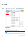
Device configuration files ................................................................................................................................................................... 6-3
Address assignment Ethernet ........................................................................................................................................................... 6-3
Resetting the IP address, switch position "000".......................................................................................................................... 6-5
Factory reset (F_Reset), switch position „900“ ............................................................................................................................ 6-6
Functional difference: switch position "000" and "900"........................................................................................................... 6-6
Set-button ................................................................................................................................................................................................ 6-6
Addressing via PACTware™ - I/O-ASSISTANT 3 (FDT/DTM) .................................................................................................... 6-7
Addressing via web server.................................................................................................................................................................. 6-7
6.2
Module status.................................................................................................................................................. 6-8
6.2.1
6.2.2
LED behavior ........................................................................................................................................................................................... 6-8
Status and Control Word of the TBEN-L stations......................................................................................................................6-10
6.3
Protocols........................................................................................................................................................ 6-12
6.3.1
6.3.2
6.3.3
Multi protocol functionality .............................................................................................................................................................6-12
Explicit/manual protocol selection ...............................................................................................................................................6-12
Protocol dependent functions........................................................................................................................................................6-12
6.4
Modbus TCP................................................................................................................................................... 6-13
6.4.1
6.4.2
6.4.3
6.4.4
6.4.5
6.4.6
6.4.7
6.4.8
6.4.9
6.4.10
6.4.11
6.4.12
Implemented Modbus functions ...................................................................................................................................................6-17
Modbus-registers.................................................................................................................................................................................6-18
Data width of the I/O-modules in the Modbus-register area ..............................................................................................6-20
Register mapping of the TBEN-L stations ...................................................................................................................................6-21
Register 100Ch: „Station-Status“ ....................................................................................................................................................6-26
Register 1130h: „Modbus-Connection-Mode“ ..........................................................................................................................6-27
Register 1131h: „Modbus-Connection-Timeout“.....................................................................................................................6-27
Register 0x113C and 0x113D: „Restore Modbus-Connection-Parameters” ..................................................................6-27
Register 0x113E and 0x113F: "Save Modbus-Connection-Parameters" ..........................................................................6-28
Bit areas: mapping of input-discrete- and coil-areas ..............................................................................................................6-28
Error behavior (watchdog) ...............................................................................................................................................................6-28
Parameters and diagnostic messages of the I/O channels ..................................................................................................6-29
6.5
EtherNet/IP™.................................................................................................................................................. 6-30
6.5.1
The EtherNet/IP™ Communications Profile ................................................................................................................................6-30
ii
D301324 0514 - TBEN-L/TBDP-L
6.5.2
6.5.3
6.5.4
6.5.5
6.5.6
6.5.7
EDS-file .................................................................................................................................................................................................... 6-32
Diagnostic messages via process data ........................................................................................................................................ 6-32
QC - QuickConnect ............................................................................................................................................................................ 6-33
Device Level Ring (DLR) .................................................................................................................................................................... 6-34
EtherNet/IP™ Standard Classes ....................................................................................................................................................... 6-35
VSC-Vendor Specific Classes............................................................................................................................................................ 6-55
6.6
PROFINET ...................................................................................................................................................... 6-63
6.6.1
6.6.2
6.6.3
6.6.4
6.6.5
6.6.6
6.6.7
Install GSD files..................................................................................................................................................................................... 6-65
FSU - Fast Start-Up (prioritized startup) ...................................................................................................................................... 6-65
MRP (Media Redundancy Protocol) .............................................................................................................................................. 6-66
PROFINET-diagnostics ....................................................................................................................................................................... 6-67
Parameters............................................................................................................................................................................................. 6-71
Description of user data for acyclic services.............................................................................................................................. 6-72
Description of the acyclic I/O-channel user data..................................................................................................................... 6-74
7
Module family TBDP-L
7.1
Configuration...................................................................................................................................................7-2
7.1.1
7.1.2
7.1.3
7.1.4
7.1.5
General .......................................................................................................................................................................................................7-2
GSD files.....................................................................................................................................................................................................7-2
Address setting .......................................................................................................................................................................................7-2
Transmission rates .................................................................................................................................................................................7-2
Bus termination.......................................................................................................................................................................................7-2
7.2
Module status ..................................................................................................................................................7-3
7.2.1
LED-displays .............................................................................................................................................................................................7-3
7.3
Diagnostics.......................................................................................................................................................7-5
7.3.1
7.3.2
Module-status (device specific diagnostics).................................................................................................................................7-5
Channel specific diagnostics..............................................................................................................................................................7-5
7.4
Parameterization ............................................................................................................................................7-8
7.4.1
7.4.2
Station parameters ................................................................................................................................................................................7-8
Parameters for I/O channels ..............................................................................................................................................................7-8
8
The web server
8.1
IP address ........................................................................................................................................................8-2
8.2
Start page of the web server (Home) .............................................................................................................8-3
8.3
Station Diagnostics .........................................................................................................................................8-4
8.4
Ethernet Statistics ...........................................................................................................................................8-5
8.5
Links..................................................................................................................................................................8-6
8.6
Login / password .............................................................................................................................................8-7
8.7
Change Admin Password ................................................................................................................................8-8
8.8
Network Configuration ...................................................................................................................................8-9
8.8.1
Change network parameters (port settings, IP address, etc.) ............................................................................................. 8-10
8.9
Station Configuration .................................................................................................................................. 8-11
8.9.1
Configuration of the field bus interface...................................................................................................................................... 8-11
8.10
I/O-parameters ............................................................................................................................................. 8-12
D301324 0514 - TBEN-L/TBDP-L
iii
8.10.1 Parameterization of the in-/ outputs ............................................................................................................................................8-12
9
Access via I/O-ASSISTANT 3 (FDT/DTM), PACTware
9.1
General ............................................................................................................................................................ 9-2
9.1.1
Addressing via I/O-ASSISTANT 3 (FDT/DTM) ............................................................................................................................... 9-3
10
Guidelines for Electrical Installation
10.1
General notes ................................................................................................................................................ 10-2
10.1.1
10.1.2
10.1.3
10.1.4
General ....................................................................................................................................................................................................10-2
Cable routing.........................................................................................................................................................................................10-2
Lightning protection ..........................................................................................................................................................................10-3
Transmission media ............................................................................................................................................................................10-3
10.2
Electromagnetic compatibility (EMC) ......................................................................................................... 10-4
10.2.1 Ensuring electromagnetic compatibility.....................................................................................................................................10-4
10.2.2 Grounding of inactive metal components .................................................................................................................................10-4
10.2.3 PE connection .......................................................................................................................................................................................10-4
10.3
Shielding of cables........................................................................................................................................ 10-5
10.4
Potential compensation ............................................................................................................................... 10-6
10.4.1 Switching inductive loads ................................................................................................................................................................10-6
10.4.2 Protection against Electrostatic Discharge (ESD).....................................................................................................................10-6
11
Glossary
12
Index
iv
D301324 0514 - TBEN-L/TBDP-L
1
About this manual
1.1
Documentation concept.................................................................................................................... 2
1.2
Explanation of symbols used ............................................................................................................ 3
1.2.1
1.2.2
Warnings .................................................................................................................................................................................................3
Further notes .........................................................................................................................................................................................3
1.3
General notes .................................................................................................................................... 4
1.3.1
1.3.2
Prescribed use .......................................................................................................................................................................................4
Notes concerning planning/installation of this product .......................................................................................................4
D301323 0514 - TBEN-L/TBDP-L
1-1
About this manual
1.1
Documentation concept
This manual contains all information about the product families TBEN and TBDP, the TURCK block I/Os
in protection class IP65/IP67/IP69K.
TBEN-L:
Compact I/O-modules for Ethernet with multiprotocol functionality ((EtherNet/IP™, Modbus TCP and
PROFINET).
TBDP-L:
Compact I/O-modules for PROFIBUS-DP
The following chapters contain:
the general technical data and station properties,
a description of the function and the features of the single devices in this type series
a description of the stations' representation in the different Ethernet-protocols,
a description of the devices' handling in the different PLC-applications,
1-2
D301323 0514 - TBEN-L/TBDP-L
Explanation of symbols used
1.2
1.2.1
Explanation of symbols used
Warnings
Action-related warnings are placed next to potentially dangerous work steps and are marked by
graphic symbols. Each warning is initiated by a warning sign and a signal word that expresses the gravity of the danger. The warnings have absolutely to be observed.
DANGER!
DANGER indicates an immediately dangerous situation, with high risk, the death or severe
injury, if not avoided.
WARNING!
WARNING indicates a potentially dangerous situation with medium risk, the death or severe
injury, if not avoided.
CAUTION!
CAUTION indicates a potentially dangerous situation with low risk, middle or low injury, if not
avoided.
ATTENTION!
ATTENTION indicates a situation that may lead to property damage, if it is not avoided.
1.2.2
Further notes
NOTE
In NOTES you find tips, recommendations and important information. The notes facilitate
work, provide more information on specific actions and help to avoid overtime by not following the correct procedure.
TECHNICAL BASICS
The TECHNICAL BASICS offer technical information, basics and background information. This
information lead to a better understanding of the device functions for example. The experienced user can skip this information.
CALL TO ACTION
This symbol identifies steps that the user has to perform.
RESULTS OF ACTION
This symbol identifies relevant results of steps
D301323 0514 - TBEN-L/TBDP-L
1-3
About this manual
1.3
General notes
Please read this section carefully. Safety aspects cannot be left to chance when dealing with electrical
equipment.
This manual includes all information necessary for the prescribed use of the TBEN-L and TBDP-L-stations. It has been specially conceived for personnel with the necessary qualifications.
1.3.1
Prescribed use
The devices described in this manual must be used only in applications prescribed in this manual or in
the respective technical descriptions, and only with certified components and devices from third party
manufacturers.
Appropriate transport, storage, deployment and mounting as well as careful operating and thorough
maintenance guarantee the trouble-free and safe operation of these devices.
1.3.2
Notes concerning planning/installation of this product
All respective safety measures and accident protection guidelines must be considered carefully and
without exception.
1-4
D301323 0514 - TBEN-L/TBDP-L
2
General Information
2.1
Safety Applications ........................................................................................................................... 2
2.2
Safety in the web server.................................................................................................................... 2
2.2.1
Webserver-logout ...............................................................................................................................................................................2
2.3
PROFIenergy ..................................................................................................................................... 2
D301323 0514 - TBEN-L/TBDP-L
2-1
General Information
2.1
Safety Applications
At the moment, TURCK does not offer TBEN/TBDP-modules for Safety applications.
2.2
Safety in the web server
In the web server, a default-password is assigned in the TBEN-L-module for the administrator access
(see also Change Admin Password (page 8-8)).
In order to make misuse by third parties more difficult, it can be necessary to change the password.
This should be done in the context of the network security concept for the complete facility in which
the modules are placed.
2.2.1
Webserver-logout
In order to disconnect a logged in user/PC with administrator rights from the web server, a logout is
necessary.
If only the web browser is closed, the last active access is reactivated when opening the web server
again from the same PC, which means, possibly with all administrator rights.
2.3
PROFIenergy
Not supported at the moment.
2-2
D301323 0514 - TBEN-L/TBDP-L
3
General technical data
3.1
General.............................................................................................................................................. 2
3.2
General information on TBEN-L ........................................................................................................ 3
3.3
General information on TBDP-L ........................................................................................................ 3
3.4
General technical data ...................................................................................................................... 4
3.4.1
3.4.2
Technical data .......................................................................................................................................................................................4
Dimension drawing.............................................................................................................................................................................6
D301323 0514 - TBEN-L/TBDP-L
3-1
General technical data
3.1
General
This chapter contains device-independent data such as dimensions, general technical data, etc. for the
stations of the product lines TBEN-L and TBDP-L.
NOTE
Station-specific information can be found in the single station descriptions within the respective chapters of this manual.
3-2
D301323 0514 - TBEN-L/TBDP-L
General information on TBEN-L
3.2
General information on TBEN-L
The devices of the TBEN-L product family provide the following features:
direct connection of up to 16 digital in- and outputs to the field bus
protocols: EtherNet/IP™, Modbus TCP and PROFINET RT in one single device
channel-related short-circuit diagnosis of outputs and slot-related short-circuit diagnosis of the sensor/actuator supply voltage
Ethernet-connection with two 4-pole, d-coded M12 x 1 connectors
integrated Ethernet-switch for building up a line-topology
3.3
General information on TBDP-L
The devices of the TBDP-L product family provide the following features:
direct connection of up to 16 digital in- and outputs to the field bus
channel-related short-circuit diagnosis of outputs and slot-related short-circuit diagnosis of the sensor/actuator supply voltage
PROFIBUS-DP-connection with two 5-pole, b-coded M12 x 1 connectors
D301323 0514 - TBEN-L/TBDP-L
3-3
General technical data
3.4
3.4.1
General technical data
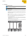
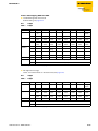
Technical data
Table 3-1:
Technical data of
the TBxx-stations
Supply voltage
V1 (incl. electronics supply)
Permissible range
V2
Permissible range
Electrical isolation
24 V DC
18 … 30 V DC
24 V DC
18 … 30 V DC
galvanic isolation between V1 and V2
Connectors
Ethernet
2 x M12-female (OUT), 4-pole, D-coded
PROFIBUS
1 x M12-male (IN), 5-pole, B-coded
1 x M12-female (OUT), 5-pole, B-coded
Power supply
7/8" connector, 4-/5-pole
Inputs / Outputs
M12-connector, 5-pole
Isolation voltages
V1 to V2
≥ 500 V AC
V1/V2 to field bus
≥ 500 V AC
Protocol properties
Modbus TCP
Address assignment
Static IP (rotary coding switch),
BOOTP, DHCP
Supported Function Codes
FC1, FC2, FC3, FC4, FC5, FC6, FC15, FC16, FC23
Number of connections
8
EtherNet/IP™
address assignment
according to EtherNet/IP™ standard
Quick Connect (QC)
< 150 ms
Device Level Ring (DLR)
supported
Number of connections
3
PROFINET
3-4
Address assignment
DCP
MinCycleTime
1 ms
D301323 0514 - TBEN-L/TBDP-L
General technical data
Fast Start-Up (FSU)
< 150 ms
Diagnosis
according to PROFINET Alarm Handling
Topology detection
supported
Automatic address assignment
supported
Media Redundancy Protocol (MRP)
supported
Housing
Fibre-glass reinforced Polyamide (PA6-GF30)
Size
60.4 × 230.4 × 24 mm (B × L × H)
Window material
Lexan
Screw material
303 Stainless Steel
halogen-free
yes
Mounting
Mounting distance station to station
Protection class
via 2 through-holes, Ø 6.3 mm
≥ 50 mm
Valid for operation in the ambient temperatures
mentioned below, with sufficient ventilation as well
as maximum load (horizontal mounting).
In case of low simultaneity factors and low ambient
temperatures, mounting distances of < 50 mm may
be possible.
IP65/IP67/IP69K
Tests
Vibration test
according to EN 60068-2-6/ IEC 68-2-47
Acceleration up to 20 g
Drop and topple
according to IEC 60068-2-31/ IEC 60068-2-32 1
Shock test
according to EN 60068-2-27
EMC
according to EN 61131-2
Temperature range
– Operating temperature
- 40 °C to + 70 °C (- 40 °F to + 158 °F)
– Storage temperature
- 40 °C to + 70 °C (- 40 °F to + 158 °F)
D301323 0514 - TBEN-L/TBDP-L
3-5
General technical data
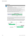
3.4.2
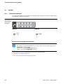
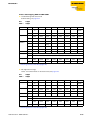
Dimension drawing
Figure 3-1:
Dimensions for
the TBxx-stations
38,8
30,2 24
P1
C4
C3
C2
C1
X1
6,3
60,4
P2
C8
C7
C6
218
C5
X2
230,5
3-6
D301323 0514 - TBEN-L/TBDP-L
4
Connection options at the gateway
4.1
Field bus............................................................................................................................................ 2
4.1.1
4.1.2
Connection to Ethernet .....................................................................................................................................................................2
– Ethernet connection for QC-/FSU-applications ....................................................................................................................2
Connection to PROFIBUS...................................................................................................................................................................3
4.2
Supply voltages ................................................................................................................................ 4
4.2.1
4.2.2
Pin assignment......................................................................................................................................................................................4
Supply concept .....................................................................................................................................................................................5
4.3
Inputs/outputs .................................................................................................................................. 6
4.4
Grounding/ shielding concept .......................................................................................................... 7
4.4.1
Grounding the station (FE) ...............................................................................................................................................................8
– General.................................................................................................................................................................................................8
– Dismounting the metal clamp ....................................................................................................................................................8
– Mounting the metal clamp...........................................................................................................................................................8
D301323 0514 - TBEN-L/TBDP-L
4-1
Connection options at the gateway
4.1
4.1.1
Field bus
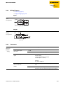
Connection to Ethernet
The connection to Ethernet is realized via the integrated auto-crossing switch is done using two 4-pole,
D-coded M12 x 1-Ethernet-connectors.
Figure 4-1:
Pin assignment of
M12 x 1-Ethernetfemale connectors, 4-pole
Ethernet M12 x 1
ETH1 (P1)
ETH2 (P2)
v
2
1
4
v
1 = TD
3 2 = RD
3 = TD
4 = RD
+
+
–
–
2
1
P1
4
1 = RD
2 = TD
3 3 = RD
4 = TD
+
+
–
–
P2
Ethernet connection for QC-/FSU-applications
NOTE
Please observe the following for QuickConnect (QC)- and Fast Start-Up (FSU)-applications:
– do not use a crossover-cable
– ETH1 = connector for incoming Ethernet-line
– ETH2 = connector for outgoing Ethernet-line
Further information concerning QuickConnect and FSU can be found here:
QuickConnect in TBEN-L (page 6-33)
FSU - Fast Start-Up (prioritized startup) (page 6-65)
4-2
D301323 0514 - TBEN-L/TBDP-L
Field bus
4.1.2
Connection to PROFIBUS
PROFIBUS-DP-connection with two 5-pole, b-coded M12 x 1 connectors
Figure 4-2:
PROFIBUS M12 x 1
Pin assignment of
M12 x 1-Ethernetfemale connectors, b-coded
BUS IN (P1), male connector
w
2
1
3
4
5
D301323 0514 - TBEN-L/TBDP-L
1
2
3
4
5
Flansch
=5V
= BUS-A
= GND
= BUS-B
= n.c.
= Schirm
BUS OUT (P2), female connector
v
2
3
1
5
4
4-3
Connection options at the gateway
4.2
4.2.1
Supply voltages
Pin assignment
The power supply is realized via 7/8" male connectors on the module.
TBEN-L1 series: 5-pole
TBDP-L2 series: 5-pole
TBEN-L4 line: 4-pole
V1 and V2 are galvanically isolated.
Figure 4-3:
Power supply
Supply voltage 7/8“, 5-pole
w
4
3
5
v
2
1
1 = V2 (–)
2 = V1 (–)
3 = FE
4 = V1 (+)
5 = V2 (+)
3
2
4
1
5
X1
X2
X1= voltage IN
X2 = voltage OUT for supplying the next node
V1 = supply voltage 1 (incl. supply of electronics)
V2 = supply voltage 2
Supply voltage 7/8“, 4-pole
w
v
3
4
1
2
1 = 24 VDC V2
2 = 24 VDC V1 3
3 = GND V1
4
4 = GND V2
X1
1
2
X2
X1= voltage IN
X2 = voltage OUT for supplying the next node
V1 = supply voltage 1 (incl. supply of electronics)
V2 = supply voltage 2
NOTE
V1 and V2 are fed and monitored separately. In case of an undercut of the admissible voltage,
the connectors are switched-off according to the module's supply concept (see Supply concept (page 4-5)).
In case of an undervoltage at V2, the "POWER" LED changes from green to red. In case of an
undervoltage at V1, the "POWER" LED is turned off.
4-4
D301323 0514 - TBEN-L/TBDP-L
Supply voltages
4.2.2
Supply concept
All TBxx-modules are supplied via two separate voltages V1 and V2.
The I/O-channels are therefore consequently separated into the different potential groups "detachable
I/O" (supplied through V2) and "non-detachable" I/O (supplied through V1).
This allows a safety shutdown of parts of an installation via emergency-off circuits even when using the
highly flexible 16DXP-module variants.
V1 = supply of module electronics and the respective connectors
V2 = supply of module electronics and the respective connectors (separately detachable)
Figure 4-4:
Module supply overview
TBxx-L1-16DIP
V1
TBxx-L1-16DOP
V2
TBxx-L1-8DIP-8DOP
V1
V2
D301323 0514 - TBEN-L/TBDP-L
V1
V2
TBxx-L1-16DXP
V1
V2
4-5
Connection options at the gateway
4.3
Inputs/outputs
The connection of sensors and actuators is realized via 8 M12 x 1-connectors.
Figure 4-5:
M12 x 1-connectors. for in- and
outputs
Inputs/outputs M12 x 1
v
2
3
1
5
4-6
The pin assignment and the wiring diagrams can be found in the module descriptions
chapter 5, Module types.
4
D301323 0514 - TBEN-L/TBDP-L
Grounding/ shielding concept
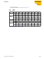
4.4
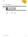
Grounding/ shielding concept
The grounding/ shielding concept of the TBxx-modules allows the separate grounding of fieldbus- and
I/O-part.
Figure 4-6:
Equivalent circuit
diagram shielding
concept
X1
X2
C1
C5
4 x 15 nF
C2
C6
C3
C7
C4
C8
1 nF
2,2 MΩ
P1
P2
Figure 4-7:
Grounding components
1 metal clamp
2 metal ring
3 mounting screw
1
2
3
The metal clamp (1) at the M12-connectors for the fieldbus connection (P1, P2) connects the shield of
the fieldbus lines.
The metal ring (2) is situated under the metal clamp an connects the functional earth of the
7/8'' connectors for the voltage supply (pin 3) to the FE of the M12-connectors (pin 5) for the connection
of the sensors and actuators.
By mounting the module onto a mounting plate through the mounting hole, the mounting screw is
used to realize the connection to the reference potential of the installation.
D301323 0514 - TBEN-L/TBDP-L
4-7
Connection options at the gateway
4.4.1
Grounding the station (FE)
NOTE
Further information about cable routing, shielding etc. of TBxx-modules can be found in
chapter 10: Guidelines for Electrical Installation.
General
Metal clamp and metal ring are connected.
The mounting screw (3) through the station's mounting hole connects the shield of the fieldbus lines
to the FE of power supply and sensors/actuators and the installation's reference potential.
If a common reference potential is not desirable, remove the metal clamp for decoupling and/or
mounting the station by using a plastic screw.
Dismounting the metal clamp
Use a slim slotted screwdriver in order to lift up and remove the metal clamp.
Figure 4-8:
Dismounting the
metal clamp
Mounting the metal clamp
Place the metal clamp between the fieldbus connectors by using a screwdriver in such way that the
clamp contacts the metal housing of the connectors.
The shielding of the fieldbus lines is now again connected to the metal clamp.
Figure 4-9:
Replacing the
metal clamp
4-8
D301323 0514 - TBEN-L/TBDP-L
5
Module types
5.1
Block diagrams TBxx......................................................................................................................... 2
5.2
TBxx-Lx-16DIP .................................................................................................................................. 3
5.2.1
5.2.2
5.2.3
5.2.4
Technical data .......................................................................................................................................................................................3
Wiring diagrams ...................................................................................................................................................................................4
– Inputs....................................................................................................................................................................................................4
Parameters..............................................................................................................................................................................................4
Diagnostic messages ..........................................................................................................................................................................5
5.3
TBxx-Lx-16DOP ................................................................................................................................. 6
5.3.1
5.3.2
5.3.3
5.3.4
Technical data .......................................................................................................................................................................................6
Wiring diagrams ...................................................................................................................................................................................6
– Outputs................................................................................................................................................................................................6
Parameters..............................................................................................................................................................................................7
Diagnostic messages ..........................................................................................................................................................................7
5.4
TBxx-Lx-8DIP-8DOP .......................................................................................................................... 8
5.4.1
5.4.2
5.4.3
5.4.4
Technical data .......................................................................................................................................................................................8
Wiring diagrams ...................................................................................................................................................................................9
– Inputs....................................................................................................................................................................................................9
– Outputs................................................................................................................................................................................................9
Parameters..............................................................................................................................................................................................9
Diagnostic messages ....................................................................................................................................................................... 10
5.5
TBxx-Lx-16DXP ............................................................................................................................... 11
5.5.1
5.5.2
Technical data .................................................................................................................................................................................... 11
Wiring diagrams ................................................................................................................................................................................ 12
– Analog inputs and outputs........................................................................................................................................................ 12
Parameters........................................................................................................................................................................................... 12
Diagnostic messages ....................................................................................................................................................................... 13
5.5.3
5.5.4
D301323 0514 - TBEN-L/TBDP-L
5-1
Module types
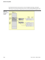
5.1
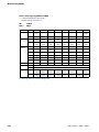
Block diagrams TBxx
Figure 5-1:
Block diagrams
X1
V1
+ –
4 2
+
5
X2
V2
–
1
V1
+ –
4 2
FE
3
+
5
V2
–
1
FE
3
Supply
Input
V1 +
V2 +
120 mA
V1 +
IN Diag
1 VAUX1
4 IN
Input
2 IN
3 V1 –
5 FE
Output
µC
120 mA
V2 +
V1 Diag
V2 Diag
IN Diag
BUS
μC
ERR
OUT Diag
4 OUT
Output
2 OUT
OUT Diag
3 V2 –
5 FE
Rotary switches
In/Output
Bus
120 mA
V1 +
IN Diag
Bus
Ethernet
OUT Diag
ETH1
3 V1 –
5 FE
3
1
4
4
P1
P2
In/Output
120 mA
V2 +
IN Diag
Bus
PROFIBUS
OUT Diag
PROFIBUS
3
4
P1
1
1
5
2 IN/OUT
3 V2 –
5 FE
2
5
1 VAUX2
4 IN/OUT
I/O
2
5-2
2 IN/OUT
2
ETH2
3
1
1 VAUX1
4 IN/OUT
I/O
Ethernet
2
1 VAUX2
3
4
P2
D301323 0514 - TBEN-L/TBDP-L
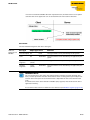
TBxx-Lx-16DIP
5.2
TBxx-Lx-16DIP
The station offers sixteen digital inputs for 3-wire PNP sensors.
5.2.1
Technical data
Table 5-1:
Technical data
TBxx-Lx-16DIP
Type designation
TBxx-Lx-16DIP
Power supply
24 V DC from operating voltage
Permissible range
18 … 30 V DC
Operational current (from V1)
< 150 mA
Sensor/actuator supply VAUX1
Supply connector C1-C8 from V1
120 mA per connector, short-circuit proof
Digital inputs
Number of channels
16
Input type
PNP
Switching threshold
EN 61131-2 type 3, PNP
Low level signal voltage
<5V
High level signal voltage
> 11 V
Low level signal current
< 1.5 mA
High level signal current
> 2 mA
Switch-on delay
2.5 ms
Type of input diagnostics
channel diagnostics
Electrical isolation
galvanic isolation to the field bus
NOTE
General technical data concerning the products of the TBxx-Lx-series can be found in
chapter 3.
D301323 0514 - TBEN-L/TBDP-L
5-3
Module types
5.2.2
Wiring diagrams
→ Field bus (page 4-2)
→ Supply voltages (page 4-4)
Inputs
Figure 5-2:
Inputs,
pin assignment
5 FE
3 BU –
4 BK
1 BN +
2 WH
3 BU –
vC1...C8
5.2.3
Parameters
Table 5-2:
Parameters
Parameter name
Value
Description
A default
setting
Invert digital input
(Inv. DIx)
0 = no A
1 = yes
Inverts the digital input signal.
Pulse stretching input
0 - 255
Stretching of the input signal from 10 to 2550 ms.
Default setting:
0 = pulse stretching deactivated
(standard pulse = 2,5 ms)
example:
10 = pulse of 100 ms
Further information about the parameters can be found in the fieldbus specific chapters.
TBEN-L
EtherNet/IP™: Digital Versatile Module Class (VSC117) (page 6-60) ff.
Modbus TCP: Register mapping of the TBEN-L stations (page 6-21) ff.
PROFINET: Parameters (page 6-71)
TBDP-L
chapter 7.4, Parameterization (page 7-8)
5-4
D301323 0514 - TBEN-L/TBDP-L
TBxx-Lx-16DIP
5.2.4
Diagnostic messages
Table 5-3:
Diagnostic messages
Diagnosis
Description
SCSx
Overload of the supply voltage at the respective connector
Further information about the diagnostic data mapping can be found in the fieldbus specific chapters.
TBEN-L
Modbus TCP: Register mapping of the TBEN-L stations (page 6-21) ff.
EtherNet/IP™: Digital Versatile Module Class (VSC117) (page 6-60) ff.
PROFINET: PROFINET-diagnostics (page 6-67)
TBDP-L
chapter 7.3, Diagnostics (page 7-5)
D301323 0514 - TBEN-L/TBDP-L
5-5
Module types
5.3
TBxx-Lx-16DOP
The station offers sixteen digital inputs for DC actuators.
5.3.1
Technical data
Table 5-4:
Technical data
TBxx-Lx-16DOP
Type designation
TBxx-Lx-16DOP
Power supply
24 V DC from operating voltage
Permissible range
18 … 30 V DC
Operational current (from V1)
< 150 mA
Sensor/actuator supply VAUX2
Supply connector C1-C8 from V2,
120 mA per connector, short-circuit proof
Digital outputs
Number of channels
16
Output type
PNP
Output voltage
24 VDC from potential group
Load type
ohmic, inductive, lamp load
Simultaneity factor
0,28 for entire module,
total current max. 9 A per module
Type of output diagnostics
channel diagnostics
Electrical isolation
galvanic isolation to the field bus
NOTE
General technical data concerning the products of the TBxx-Lx-series can be found in
chapter 3.
5.3.2
Wiring diagrams
→ Field bus (page 4-2)
→ Supply voltages (page 4-4)
Outputs
Figure 5-3:
Outputs,
pin assignment
5 FE
4 BK
1 BN +
2 WH
3 BU –
v
C1...C8
5-6
D301323 0514 - TBEN-L/TBDP-L
TBxx-Lx-16DOP
5.3.3
Parameters
Table 5-5:
Parameters
Parameter name
Value
Description
A default
setting
Manual output reset
after overcurrent
(SROx)
0 = no A
The output switches on automatically after an overload.
1 = yes
The output is manually switched-off after an overload until a new set-command is given (rise and fall).
Further information about the parameters can be found in the fieldbus specific chapters.
TBEN-L
EtherNet/IP™: Digital Versatile Module Class (VSC117) (page 6-60) ff.
Modbus TCP: Register mapping of the TBEN-L stations (page 6-21) ff.
PROFINET: Parameters (page 6-71)
TBDP-L
chapter 7.4, Parameterization (page 7-8)
5.3.4
Diagnostic messages
Table 5-6:
Diagnostic
messages
Diagnosis
Description
SCSx
Overload of the supply voltage at the respective connector
SCOx
Overcurrent at the respective output
Further information about the diagnostic data mapping can be found in the fieldbus specific chapters.
TBEN-L
Modbus TCP: Register mapping of the TBEN-L stations (page 6-21) ff.
EtherNet/IP™: Digital Versatile Module Class (VSC117) (page 6-60) ff.
PROFINET: PROFINET-diagnostics (page 6-67)
TBDP-L
chapter 7.3, Diagnostics (page 7-5)
D301323 0514 - TBEN-L/TBDP-L
5-7
Module types
5.4
TBxx-Lx-8DIP-8DOP
The station offers eight digital inputs for 3-wire PNP-sensors and eight digital outputs for DC actuators.
5.4.1
Technical data
Table 5-7:
Technical data
TBxx-Lx-8DIP8DOP
Type designation
TBxx-Lx-8DIP-8DOP
Power supply
24 V DC from operating voltage
Permissible range
18 … 30 V DC
Operating current
< 150 mA
Sensor/actuator supply VAUX1/VAUX2
supply of connectors
C1 - C4 from V1
C5 - C8 from V2
120 mA per connector, short-circuit proof
Digital inputs
Number of channels
8
Input type
PNP
Switching threshold
EN 61131-2 type 3, PNP
Low level signal voltage
<5V
High level signal voltage
> 11 V
Low level signal current
< 1.5 mA
High level signal current
> 2 mA
Switch-on delay
2.5 ms
Type of input diagnostics
channel diagnostics
Digital outputs
Number of channels
8
Output type
PNP
Output voltage
24 VDC from potential group
Load type
ohmic, inductive, lamp load
Simultaneity factor
0,56 for entire module,
total current max. 9 A per module
Type of output diagnostics
channel diagnostics
Electrical isolation
galvanic isolation to the field bus
NOTE
General technical data concerning the products of the TBxx-Lx-series can be found in
chapter 3.
5-8
D301323 0514 - TBEN-L/TBDP-L
TBxx-Lx-8DIP-8DOP
5.4.2
Wiring diagrams
→ Field bus (page 4-2)
→ Supply voltages (page 4-4)
Inputs
Figure 5-4:
Inputs,
pin assignment
5 FE
3 BU –
4 BK
1 BN +
2 WH
3 BU –
v
C1...C4
Outputs
Figure 5-5:
Outputs,
pin assignment
5 FE
4 BK
1 BN +
2 WH
3 BU –
v
C5...C8
5.4.3
Parameters
Table 5-8:
Parameters
Parameter name
Value
A default
setting
Invert digital input
(Inv. DIx)
0 = no A
Pulse stretching
input
Description
1 = yes
Inverts the digital input signal.
0 - 255
Stretching of the input signal from 10 to 2550 ms.
Default setting:
0 = pulse stretching deactivated
(standard pulse = 2,5 ms)
example:
10 = pulse of 100 ms
Manual output reset
after overcurrent
(SROx)
D301323 0514 - TBEN-L/TBDP-L
0 = no A
The output switches on automatically after an overload.
1 = yes
The output is manually switched-off after an overload until a new set-command is given (rise and fall).
5-9
Module types
Further information about the parameter data mapping can be found in the fieldbus specific chapters.
TBEN-L
EtherNet/IP™: Digital Versatile Module Class (VSC117) (page 6-60) ff.
Modbus TCP: Register mapping of the TBEN-L stations (page 6-21) ff.
PROFINET: Parameters (page 6-71)
TBDP-L
chapter 7.4, Parameterization (page 7-8)
5.4.4
Diagnostic messages
Table 5-9:
Diagnostic messages
Diagnosis
Description
SCSx
Overload of the supply voltage at the respective connector
SCOx
Overcurrent at the respective output
Further information about the diagnostic data mapping can be found in the fieldbus specific chapters.
TBEN-L
Modbus TCP: Register mapping of the TBEN-L stations (page 6-21) ff.
EtherNet/IP™: Digital Versatile Module Class (VSC117) (page 6-60) ff.
PROFINET: PROFINET-diagnostics (page 6-67)
TBDP-L
chapter 7.3, Diagnostics (page 7-5)
5-10
D301323 0514 - TBEN-L/TBDP-L
TBxx-Lx-16DXP
5.5
TBxx-Lx-16DXP
The station is equipped with sixteen channels, which can be configured individually, depending on the
specific application requirements. Up to sixteen 3-wire PNP sensors or sixteen
PNP DC actuators with a maximum output current of 2 A per output can be connected.
5.5.1
Technical data
Table 5-10:
Technical data
TBxx-Lx-16DXP
Type designation
TBxx-Lx-16DXP
Power supply
24 V DC from operating voltage
Permissible range
18 … 30 V DC
Operating current
< 150 mA
Sensor/actuator supply VAUX1/VAUX2
supply of connectors
C1 - C4 from V1
C5 - C8 from V2
120 mA per connector, short-circuit proof
Digital inputs
Number of channels
16
Input type
PNP
Switching threshold
EN 61131-2 type 3, PNP
Low level signal voltage
<5V
High level signal voltage
> 11 V
Low level signal current
< 1.5 mA
High level signal current
> 2 mA
Switch-on delay
2.5 ms
Type of input diagnostics
channel diagnostics
Digital outputs
Number of channels
16, DC actuators
Output type
PNP
Output voltage
24 VDC from potential group
Load type
ohmic, inductive, lamp load
Simultaneity factor
0,56 for entire module,
total current max. 9 A per module
Type of output diagnostics
channel diagnostics
Electrical isolation
galvanic isolation to the field bus
NOTE
General technical data concerning the products of the TBxx-Lx-series can be found in
chapter 3.
D301323 0514 - TBEN-L/TBDP-L
5-11
Module types
5.5.2
Wiring diagrams
→ Field bus (page 4-2)
→ Supply voltages (page 4-4)
Analog inputs and outputs
Figure 5-6:
Inputs/outputs,
pin assignment
5 FE
3 BU –
4 BK
1 BN +
2 WH
3 BU –
Sensor
or
Actuator
Sensor
or
Actuator
v
C1...C8
5.5.3
Parameters
Table 5-11:
Parameters
Parameter name
Value
A default
setting
Invert digital input
(Inv. DIx)
0 = no A
Pulse stretching
input
Description
1 = yes
The digital input signal is inverted.
0 - 255
Stretching of the input signal from 10 to 2550 ms.
Default setting:
0 = pulse stretching deactivated
(standard pulse = 2,5 ms)
example:
10 = pulse of 100 ms
Manual output reset
after overcurrent (SROx)
Activate output
(EN DOx)
0 = no A
The output switches on automatically after an overload.
1 = yes
The output is manually switched-off and on again.
0 = no
1 = yes A
Further information about the parameter data mapping can be found in the fieldbus specific chapters.
TBEN-L
EtherNet/IP™: Digital Versatile Module Class (VSC117) (page 6-60) ff.
Modbus TCP: Register mapping of the TBEN-L stations (page 6-21) ff.
PROFINET: Parameters (page 6-71)
TBDP-L
chapter 7.4, Parameterization (page 7-8)
5-12
D301323 0514 - TBEN-L/TBDP-L
TBxx-Lx-16DXP
5.5.4
Diagnostic messages
Table 5-12:
Diagnostic messages
Diagnosis
Description
SCSx
Overload of the supply voltage at the respective connector
SCOx
Overcurrent at the respective output
Further information about the diagnostic data mapping can be found in the fieldbus specific chapters.
TBEN-L
Modbus TCP: Register mapping of the TBEN-L stations (page 6-21) ff.
EtherNet/IP™: Digital Versatile Module Class (VSC117) (page 6-60) ff.
PROFINET: PROFINET-diagnostics (page 6-67)
TBDP-L
chapter 7.3, Diagnostics (page 7-5)
D301323 0514 - TBEN-L/TBDP-L
5-13
Module types
5-14
D301323 0514 - TBEN-L/TBDP-L
6
Module family TBEN-L
6.1
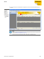
Configuration.................................................................................................................................... 3
6.1.1
6.1.2
6.1.4
6.1.5
6.1.6
6.1.7
6.1.8
Device configuration files .................................................................................................................................................................3
Address assignment Ethernet..........................................................................................................................................................3
– Mode: Static rotary ..........................................................................................................................................................................3
– Mode: BootP (300) ...........................................................................................................................................................................4
– Mode: DHCP (400)............................................................................................................................................................................4
– Mode: PGM (500)..............................................................................................................................................................................5
– Mode: PGM-DHCP (600).................................................................................................................................................................5
Resetting the IP address, switch position "000" ........................................................................................................................5
– Default setting of the gateway....................................................................................................................................................5
Factory reset (F_Reset), switch position „900“...........................................................................................................................6
Functional difference: switch position "000" and "900".........................................................................................................6
Set-button...............................................................................................................................................................................................6
Addressing via PACTware™ - I/O-ASSISTANT 3 (FDT/DTM)...................................................................................................7
Addressing via web server ................................................................................................................................................................7
6.2
Module status ................................................................................................................................... 8
6.2.1
6.2.2
LED behavior..........................................................................................................................................................................................8
Status and Control Word of the TBEN-L stations ................................................................................................................... 10
– Status Word..................................................................................................................................................................................... 10
– Control Word .................................................................................................................................................................................. 11
6.3
Protocols ......................................................................................................................................... 12
6.3.1
6.3.2
6.3.3
Multi protocol functionality .......................................................................................................................................................... 12
– General.............................................................................................................................................................................................. 12
Explicit/manual protocol selection............................................................................................................................................. 12
Protocol dependent functions ..................................................................................................................................................... 12
6.4
Modbus TCP .................................................................................................................................... 13
6.1.3
6.4.1
6.4.2
6.4.3
6.4.4
6.4.5
6.4.6
6.4.7
6.4.8
6.4.9
6.4.10
6.4.11
6.4.12
– Common Modbus description ................................................................................................................................................. 13
– Protocol description ................................................................................................................................................................... 14
Implemented Modbus functions................................................................................................................................................. 17
Modbus-registers .............................................................................................................................................................................. 18
Data width of the I/O-modules in the Modbus-register area............................................................................................ 20
Register mapping of the TBEN-L stations................................................................................................................................. 21
– TBEN-Lx-16DIP .............................................................................................................................................................................. 21
– TBEN-Lx-16DOP ............................................................................................................................................................................ 22
– TBEN-Lx-8DIP-8DOP .................................................................................................................................................................... 23
– TBEN-Lx-16DXP ............................................................................................................................................................................. 24
– Meaning of the register bits ...................................................................................................................................................... 25
Register 100Ch: „Station-Status“ ................................................................................................................................................. 26
Register 1130h: „Modbus-Connection-Mode“ ....................................................................................................................... 27
Register 1131h: „Modbus-Connection-Timeout“ .................................................................................................................. 27
– Behavior of the BUS LED............................................................................................................................................................. 27
Register 0x113C and 0x113D: „Restore Modbus-Connection-Parameters”................................................................ 27
Register 0x113E and 0x113F: "Save Modbus-Connection-Parameters"........................................................................ 28
Bit areas: mapping of input-discrete- and coil-areas ........................................................................................................... 28
Error behavior (watchdog)............................................................................................................................................................. 28
– Behavior of outputs...................................................................................................................................................................... 28
– Behavior of the BUS LED............................................................................................................................................................. 29
Parameters and diagnostic messages of the I/O channels ............................................................................................... 29
D301323 0514 - TBEN-L/TBDP-L
6-1
Module family TBEN-L
6.5
EtherNet/IP™ ................................................................................................................................... 30
6.5.1
The EtherNet/IP™ Communications Profile..............................................................................................................................30
– Communication profile for TBEN-L .........................................................................................................................................31
EDS-file ..................................................................................................................................................................................................32
Diagnostic messages via process data.......................................................................................................................................32
– Summarized Diagnostics ............................................................................................................................................................32
– Scheduled Diagnostics (manufacturer specific diagnosis).............................................................................................32
QC - QuickConnect ...........................................................................................................................................................................33
– Ethernet cabling for TBEN in QC applications ....................................................................................................................33
– QuickConnect in TBEN-L .............................................................................................................................................................33
Device Level Ring (DLR)...................................................................................................................................................................34
EtherNet/IP™ Standard Classes................................................................................................................................................... 35
– Identity Object (0x01) ..................................................................................................................................................................35
– Assembly Object (0x04)...............................................................................................................................................................37
– Configuration Assembly .............................................................................................................................................................38
– Process data mapping TBEN-Lx-16DIP ..................................................................................................................................43
– Process data mapping TBEN-Lx-16DOP ................................................................................................................................44
– Process data mapping TBEN-Lx-8DIP-8DOP........................................................................................................................45
– Process data mapping TBEN-Lx-16DXP.................................................................................................................................46
– Meaning of Process data bits ....................................................................................................................................................48
– Connection Manager Object (0x06)........................................................................................................................................49
– TCP/IP Interface Object (0xF5) ..................................................................................................................................................50
– Ethernet Link Object (0xF6) .......................................................................................................................................................53
VSC-Vendor Specific Classes..........................................................................................................................................................55
– Class instance of the VSC ............................................................................................................................................................55
– Gateway Class (VSC 100) .............................................................................................................................................................57
– Process Data Class (VSC102) ......................................................................................................................................................59
– Digital Versatile Module Class (VSC117)................................................................................................................................60
– Miscellaneous Parameters Class (VSC 126) ..........................................................................................................................62
6.5.2
6.5.3
6.5.4
6.5.5
6.5.6
6.5.7
6.6
PROFINET ........................................................................................................................................ 63
6.6.1
6.6.2
Install GSD files ...................................................................................................................................................................................65
FSU - Fast Start-Up (prioritized startup).....................................................................................................................................65
– Ethernet cabling for TBEN-L in QC applications .................................................................................................................65
– FSU in TBEN-L..................................................................................................................................................................................65
MRP (Media Redundancy Protocol) ............................................................................................................................................66
PROFINET-diagnostics......................................................................................................................................................................67
– TBEN-Lx-16DIP – diagnostic data mapping .........................................................................................................................67
– TBEN-Lx-16DOP – diagnostic data mapping.......................................................................................................................68
– TBEN-Lx-8DIP-8DOP – diagnostic data mapping ..............................................................................................................69
– TBEN-Lx-16DXP – diagnostic data mapping .......................................................................................................................70
Parameters ...........................................................................................................................................................................................71
– General station parameters (turck-tben) ..............................................................................................................................71
– Parameters for I/O channels .....................................................................................................................................................72
Description of user data for acyclic services ............................................................................................................................72
– Description of the acyclic gateway user data......................................................................................................................73
Description of the acyclic I/O-channel user data ...................................................................................................................74
6.6.3
6.6.4
6.6.5
6.6.6
6.6.7
6-2
D301323 0514 - TBEN-L/TBDP-L
Configuration
6.1
Configuration
This sub-chapter describes the configuration of the Ethernet-connection.
Details concerning the necessary protocol-specific configurations (Modbus TCP, EtherNet/IP™, PROFINET) can be found in the respective sub-chapters.
6.1.1
Device configuration files
The actual device configuration files for the stations can be downloaded from the TURCK-website
www.turck.com.
Information about the protocol-specific files can be found in the respective sub-chapters.
6.1.2
Address assignment Ethernet
Setting the address mode is done through the 3 rotary coding-switches on the gateway.
Figure 6-1:
Decimal rotary
coding-switches
for address setting
x 100
x 10
x1
000: 192.168.1.254
1 - 254: static rotary
300: BootP
400: DHCP
500: PGM
600: PGM-DHCP
900: F_Reset
ATTENTION!
Protective cover opened
Protection class IP65/IP67/IP69K not warranted
Screw the protective cover over the rotary coding-switches firmly
Check if seal of the protective cover is correctly placed
NOTE
After every change of the address-mode, a voltage reset must be done.
Mode: Static rotary
switch position: 001 - 254
When using the rotary-mode, the last byte of the station’s IP address can be set via the rotary coding
switches.
Addresses in the range from 0 to 255 can be allocated, whereas 1 is normally reserved for the defaultgateway and 0 and 255 for broadcast messages in the subnet.
In TURCK devices, 0 is used to reset the device to the default IP address (see Resetting the IP address,
switch position "000" (page 6-5)).
NOTE
We therefore recommend addresses in the range of 2-254.
D301323 0514 - TBEN-L/TBDP-L
6-3
Module family TBEN-L
Mode: BootP (300)
switch position: 300
Address setting is carried out by a BootP-server in the network after the start-up of the gateway.
NOTE
The IP address, as well as the default subnet mask assigned to the station by the BootP-server,
are stored permanently in the station’s EEPROM.
In case of switching the device to rotary- or PGM-mode, the settings carried out via BootP (IP
address, subnet mask, etc) will be taken from the module’s EEPROM.
PROFINET
Please assure, that in PROFINET-applications, the address assigned via a BootP-server corresponds to
the address, which is assigned in the configuration tool.
Mode: DHCP (400)
switch position: 400
Address setting is carried out by a DHCP-server in the network after the start-up of the gateway.
NOTE
The IP address, as well as the default subnet mask assigned to the station by the DHCP-server,
are stored permanently in the station’s EEPROM.
In case of switching the device to rotary- or PGM-mode, the settings carried out via DHCP (IP
address, subnet mask, etc) will be taken from the module’s EEPROM.
DHCP supports three mechanisms for IP address allocation:
In "automatic allocation", the DHCP-server assigns a permanent IP address to a client.
In "dynamic allocation", DHCP assigns an IP address to a client for a limited period of time. After this
time, or until the client explicitly relinquishes the address, the address can be re-assigned.
In "manual allocation", a client's IP address is assigned by the network administrator, and DHCP is
used simply to convey the assigned address to the client.
PROFINET
Please assure, that in PROFINET-applications, the address assigned via a BootP-server corresponds to
the address, which is assigned in the configuration tool.
6-4
D301323 0514 - TBEN-L/TBDP-L
Configuration
Mode: PGM (500)
switch position: 500
The PGM-mode enables access of the software I/O-ASSISTANT to the module’s network settings.
NOTE
In the PGM-mode, all network settings (IP address, subnet mask, etc.) are send to the module’s
internal EEPROM and stored permanently.
Mode: PGM-DHCP (600)
switch position: 600
The device sends DHCP-requests until a IP address is assigned (DHCP-server, PROFINET-controller).
The assigned IP-address is stored to the device and the DHCP-client is stopped.
Even after a restart of the device, the device sends no further DHCP-requests.
PROFINET
This mode assures a PROFINET-compliant operation of the modules.
NOTE
If a DHCP-server is used within the network, problems may occur during IP-assignment.
In this case, both, the DHCP-server as well as the PROFINET-controller (via DCP), try an IPaddress-assignment.
6.1.3
Resetting the IP address, switch position "000"
With this setting the rotary coding-switches to "000" followed by a voltage reset, the module is set to
the address 192.168.1.254 for IP-based services (seeDefault setting of the gateway (page 6-5)).
NOTE
Setting "000" is no operation mode! Please set the device to another mode after having reset
the IP address to the default values.
Default setting of the gateway
The stations' default-settings are as follows:
IP address
Subnet mask
default gateway
192.168.1.254
255.255.255.0
192.168.1.1
NOTE
The stations can be reset by the user to these default settings at any time.
To reset the module, set the 3 coding-switches on the gateway to "000" followed by a poweron reset.
ATTENTION!
Protective cover opened
Protection class IP65/IP67/IP69K not warranted
Screw the protective cover over the rotary coding-switches firmly
Check if seal of the protective cover is correctly placed
D301323 0514 - TBEN-L/TBDP-L
6-5
Module family TBEN-L
6.1.4
Factory reset (F_Reset), switch position „900“
F_Reset (Reset to factory setting)
switch position: 900
This mode sets all device-settings back to the default values and deletes all data in the device's internal
flash.
NOTE
Setting 900 is no operation mode! Please set the device to another mode after having reset
the IP address to the default values.
ATTENTION!
Protective cover opened
Protection class IP65/IP67/IP69K not warranted
Screw the protective cover over the rotary coding-switches firmly
Check if seal of the protective cover is correctly placed
6.1.5
Functional difference: switch position "000" and "900"
Table 6-1:
Functional difference "000" and
"900"
6.1.6
Switch position
Reset of...
000
900
IP address, subnet mask, gateway
Parameters
-
PROFINET device name
-
Set-button
The Set-button is placed left to the rotary coding switches under the cover at the device.
Pushing the Set-button causes a device-restart.
Figure 6-2:
Set-button
x 100
x 10
x1
ATTENTION!
Protective cover opened
Protection class IP65/IP67/IP69K not warranted
Screw the protective cover over the rotary coding-switches firmly
Check if seal of the protective cover is correctly placed
6-6
D301323 0514 - TBEN-L/TBDP-L
Configuration
6.1.7
Addressing via PACTware™ - I/O-ASSISTANT 3 (FDT/DTM)
The software-tool I/O-ASSISTANT enables direct access to the Ethernet-network via the Ethernet cable.
The IP address, as well as the subnet mask of the TURCK Ethernet stations, can be changed according
to the application by using the Busaddress Management function of the BL Service Ethernet interface
(TCP/IP) in the software I/O-ASSISTANT.
Further information about using this software can be found in chapter 9: Access via I/O-ASSISTANT 3
(FDT/DTM), PACTware (page 9-1).
6.1.8
Addressing via web server
The device's network settings can be changed under "Network Configuration" only by users having
administrator rights.
Further information concerning the web server of the TBEN-L devices and it's use can be found under
chapter 8, The web server (page 8-1).
D301323 0514 - TBEN-L/TBDP-L
6-7
Module family TBEN-L
6.2
6.2.1
Module status
LED behavior
The following table describes the protocol-independent behavior of the module LEDs.
The description of protocol-specific LED-behavior can be found in the respective sub-chapters.
Table 6-2:
LED-displays of
TBEN-L stations
LED
Color Status
Meaning
Remedy
green off
V1 missing or < 18 V DC
Check V1
PWR
TBEN-Lx-16DIP
on
TBEN-Lx-16DOP
green off
TBEN-Lx-8DIP-8DOP
on
TBEN-Lx-16DXP
red
ETHx
green on
yellow
ERR
BUS
on
V1 missing or < 18 V DC
Check V1
V1 and V2 OK
-
V2 missing or < 18 V DC
Check V2
Link established, 100 Mbps
flashing
Ethernet Traffic, 100 Mbps
on
Link established, 10 Mbps
flashing
Ethernet Traffic, 10 Mbps
off
No Ethernet link.
Check the Ethernetconnection
green on
No diagnostic message available
red
Diagnostic message pending
on
green on
red
Active connection to a master
-
flashing
Device is ready for operation
-
on
IP address conflict or restore
mode or timeout
control IP addresses
in the network
waiting for the device
to be ready for operation
flashing
Blink-/wink-command active
-
red / on
green
6-8
V1 OK
Autonegotiation and/or waiting
for DHCP-/BootP-address
assignment.
D301323 0514 - TBEN-L/TBDP-L
Module status
Table 6-2:
LED-displays of
TBEN-L stations
LED
Color Status
Meaning
green flashing A
Input active, 24 V at input
red
flashing A
Overload of the supply voltage
at
the respective connector
Both LEDs at the connector are
flashing
off
Input inactive
green flashing A
Output active
red
on
Output active,
overload/overcurrent at output
flashing A
Overload of the supply voltage
at the respective connector
Both LEDs at the connector are
flashing
off
Output inactive
Remedy
A can also occur in 1 to 16
combination
TBDP-Lx-16DIP
TBEN-Lx-16DOP
TBEN-Lx-16DXP
green flashing A
Output or input active
red
on
output active, overload/overcurrent at output
flashing A
Overload of the supply voltage
at the respective connector
Both LEDs at the connector are
flashing
off
Output or input active
Check the sensor supply
Check the sensor supply
Check the sensor supply
1 to 8
TBEN-Lx-8DIP-8DOP green flashing A
red
flashing A
Input active, 24 V at input
Overload of the supply voltage
at the respective connector
Both LEDs at the connector are
flashing
Check the sensor supply
off
D301323 0514 - TBEN-L/TBDP-L
6-9
Module family TBEN-L
Table 6-2:
LED-displays of
TBEN-L stations
LED
Color Status
Meaning
Remedy
9 to 16
TBEN-Lx-8DIP-8DOP green flashing A
red
6.2.2
Output active
on
Output active,
overload/overcurrent at output
flashing A
Overload of the supply voltage
at the respective connector
Both LEDs at the connector are
flashing
off
Output inactive
Check the sensor supply
Status and Control Word of the TBEN-L stations
The Status as well as the Control Word are mapped into the station's process data.
EtherNet/IP™
In EtherNet/IP™, the mapping can be disabled (see Gateway Class (VSC 100), GW Status Register
(page 6-58) and GW Control Register (page 6-58)).
ATTENTION!
Activate/deactivate the Status and Control Word in EtherNet/IP™
Changes in the process data mapping
Observe that activating/deactivating the Status and Control Word causes changes in the
process data mapping.
Modbus TCP
→ see Register 100Ch: „Station-Status“ (page 6-26)
PROFINET
→ see PROFINET-diagnostics (page 6-67)
Status Word
Byte
Status
6-10
Bit 7
Bit 6
Bit 5
Bit 4
Bit 3
Bit 2
Bit 1
Bit 0
0
V2
-
-
-
-
-
-
Diag
Warn
1
-
FCE
-
-
CFG
COM
V1
-
D301323 0514 - TBEN-L/TBDP-L
Module status
Meaning of the status bits
Table 6-3:
Meaning of the
status bits
Name
Meaning
Diag
Warn
Group diagnostics of the device. At least 1 channel sends diagnostics.
V2
V2 too low (< 18 V DC).
V1
V2 too low (< 18 V DC).
COM
I/O Communication Lost Error
No Communication on the module bus.
CFG
I/O Cfg Modified error
The I/O-configuration has be changed and is no longer compatible.
FCE
Force Mode Active Error
The Force Mode is activated, which means, the actual output values may no match the
ones defined and sent by the field bus.
Control Word
The Control Word has no function at the moment, it is reserves for further use.
D301323 0514 - TBEN-L/TBDP-L
6-11
Module family TBEN-L
6.3
6.3.1
Protocols
Multi protocol functionality
General
The compact I/O-stations of the TBEN-L product line combine the three Ethernet-protocols:
Modbus TCP (description page 6-13 ff.),
EtherNet/IP™ (description page 6-30) and
PROFINET (description page 6-3 ff.)
in one device.
A multi-protocol device can be operated without intervention of the user (which means, without
changes in the parameterization) in all of the three Ethernet protocols mentioned.
During the start-up, after a power-on, the module runs in "snooping" mode and detects the Ethernet
protocol which requests a link connection by listening the traffic.
If a protocol is detected, the device is set automatically to the respective protocol. After this an access
to the device from other protocols is read-only.
6.3.2
Explicit/manual protocol selection
The protocol can also be determined manually. This skips the snooping-phase and the device is permanently set to the selected protocol. An access to the device from other protocols is read-only.
The explicit protocol selection allows thus an additional locking mechanism.
6.3.3
Protocol dependent functions
PROFINET
Fast Start-UP (FSU), see FSU - Fast Start-Up (prioritized startup) (page 6-65)
Topology discovery
Address assignment via LLDP
MRP, see MRP (Media Redundancy Protocol) (page 6-66)
EtherNet/IP™
QuickConnect (QC), see QuickConnect in TBEN-L (page 6-33)
DLR (Device Level Ring), see Device Level Ring (DLR) (page 6-34)
6-12
D301323 0514 - TBEN-L/TBDP-L
Modbus TCP
6.4
Modbus TCP
Common Modbus description
NOTE
The following description of the Modbus protocol is taken from the Modbus Application Protocol Specification V1.1 of Modbus-IDA.
TECHNICAL BASICS
Modbus is an application layer messaging protocol, positioned at level 7 of the OSI model,
that provides client/server communication between devices connected on different types of
buses or networks.
The industry’s serial de facto standard since 1979, Modbus continues to enable millions of
automation devices to communicate. Today, support for the simple and elegant structure of
Modbus continues to grow.
The Internet community can access Modbus at a reserved system port 502 on the TCP/IP
stack.
Modbus is a request/reply protocol and offers services specified by function codes. Modbus
function codes are elements of Modbus request/reply PDUs (Protocol Data Unit).
It is currently implemented using:
– TCP/IP over Ethernet. (that is used for the TBEN-L modules and described in the following)
– Asynchronous serial transmission over a variety of media (wire: RS232, RS422, RS485, optical: fiber, radio, etc.)
– Modbus PLUS, a high speed token passing network.
Schematic representation of the Modbus Communication Stack (according to Modbus Application Protocol Specification V1.1 of Modbus-IDA):
Modbus Application Layer
Modbus TCP
TCP
IP
andere
Physical layer
D301323 0514 - TBEN-L/TBDP-L
Modbus plus
Master/Slave
Client/Server
Physical layer
Rsxxx
Physical layer
Ethernet
Physical layer
6-13
Module family TBEN-L
Protocol description
TECHNICAL BASICS
The Modbus protocol defines a simple protocol data unit (PDU) independent of the underlying communication layers.
The mapping of Modbus protocol on specific buses or network can introduce some additional fields on the application data unit (ADU).
The Modbus application data unit is built by the client that initiates a Modbus transaction.
The function code indicates to the server what kind of action to perform.
The Modbus application protocol establishes the format of a request initiated by a client.
The field function code of a Modbus data unit is coded in one byte. Valid codes are in the
range of 1... 255 decimal (128 – 255 reserved for exception responses).
When a message is sent from a Client to a Server device the function code field tells the server
what kind of action to perform. Function code "0" is not valid.
Sub-function codes are added to some function codes to define multiple actions.
The data field of messages sent from a client to server devices contains additional information
that the server uses to take the action defined by the function code. This can include items
like discrete and register addresses, the quantity of items to be handled, and the count of
actual data bytes in the data field.
The data field may be non-existent (= 0) in certain kinds of requests, in this case the server
does not require any additional information. The function code alone specifies the action.
If no error occurs related to the Modbus function requested in a properly received Modbus
ADU the data field of a response from a server to a client contains the data requested.
6-14
D301323 0514 - TBEN-L/TBDP-L
Modbus TCP
If an error related to the Modbus function requested occurs, the field contains an exception
code that the server application can use to determine the next action to be taken.
Data model
The data model distinguishes four basic data types:
Table 6-4:
Data types for
Modbus
Data Type
Object type Access
Comment
Discrete Inputs bit
Read
This type of data can be provided by an I/O system.
Coils
bit
Read-Write
This type of data can be alterable by an application program.
Input
Registers
16 bit,
(word)
Read
This type of data can be provided by an I/O system.
Holding
Registers
16 bit,
(word)
Read-Write
This type of data can be alterable by an application program.
TECHNICAL BASICS
For each of these basic data types, the protocol allows individual selection of 65536 data
items, and the operations of read or write of those items are designed to span multiple consecutive data items up to a data size limit which is dependent on the transaction function
code.
It’s obvious that all the data handled via Modbus (bits, registers) must be located in device
application memory.
Access to these data is done via defined access-addresses (see Modbus-registers (page 6-18)).
D301323 0514 - TBEN-L/TBDP-L
6-15
Module family TBEN-L
The example below shows the data structure in a device with digital and analog in- and outputs.
TBEN-L devices have only one data block, which can be accessed via different Modbus functions. The
access can be carried out either via registers (16-bit-access) or, for some of them, via single-bit-access.
Figure 6-3:
Picture of the
data memory of
the TBEN-L
modules
6-16
D301323 0514 - TBEN-L/TBDP-L
Modbus TCP
6.4.1
Implemented Modbus functions
The TBEN-L stations for Modbus TCP support the following functions for accessing process data, parameters, diagnostics and other services.
Table 6-5:
Implemented
functions
Function codes
No.
Function
Description
1
Read Coils
Serves for reading multiple output bits.
2
Read Discrete Inputs
Serves for reading multiple input bits.
3
Read Holding Registers
Serves for reading multiple output registers.
4
Read Input Registers
Serves for reading multiple input registers.
5
Write Single Coil
Serves for writing a single output bit.
6
Write Single Register
Serves for writing a single output register.
15
Write Multiple Coils
Serves for writing multiple output bits.
16
Write Multiple Registers
Serves for writing multiple output registers.
23
Read/Write Multiple Registers
Reading and writing of multiple registers.
D301323 0514 - TBEN-L/TBDP-L
6-17
Module family TBEN-L
6.4.2
Modbus-registers
NOTE
The Table 6-7: Mapping of Modbus registers (holding registers), page 6-19 shows the register
mapping for the different Modbus addressing methods.
Table 6-6:
Modbus registers of the
station
A ro = read only
rw = read/write
6-18
Address (hex.)
Access A
Description
0x0000 to 0x01FF
ro
packed process data of inputs
(process data length of the modules
→ see Table 6-8: Data widths of the stations
0x0800 to 0x09FF
rw
packed process data of outputs (process data length of
the modules
→ see Table 6-8: Data widths of the stations
0x1000 to 0x1006
ro
Station Identifier
0x100C
ro
Station status
→ see Table 6-10: Register 100Ch: Station status
0x1012
ro
process image length in bit for the intelligent output
modules
0x1013
ro
process image length in bit for the intelligent input modules
0x1017
ro
Register-mapping-revision
(always 1, if not, mapping is incompatible with this
description)
0x1020
ro
watchdog, actual time [ms]
0x1120
rw
watchdog predefined time [ms] (default: 0),
→ see also Error behavior (watchdog) (page 6-28)
0x1130
rw
Modbus connection mode register, page 6-27
0x1131
rw
Modbus connection timeout in sec. (Def.: 0 = never),
→ see page 6-27
0x113C to 0x113D
rw
Modbus parameter restore, → see page 6-27
(reset of parameters to default values)
0x113E to 0x113F
rw
Modbus parameter save, → see page 6-28
(permanent storing of parameters)
0x1140
rw
deactivate protocol
Deactivates explicitly the selected Ethernet-protocol:
Bit 0 = EtherNet/IP™
Bit 1 = Modbus TCP
Bit 2 = PROFINET
Bit 15 = web server
D301323 0514 - TBEN-L/TBDP-L
Modbus TCP
Table 6-6:
Modbus registers of the
station
Description
Address (hex.)
Access A
0x1141
ro
active protocol
Bit 0 = EtherNet/IP™
Bit 1 = Modbus TCP
Bit 2 = PROFINET
Bit 15 = web server
0x2400
ro
V1 [mV]: 0 at < 18 V
0x2401
ro
V2 [mV]: 0 at < 18 V
0x8000 to 0x8400
ro
process data inputs (32 registers per station)
0x9000 to 0x9400
rw
process data outputs (32 registers per station)
0xA000 to 0xA400
ro
diagnostics (32 registers per station)
0xB000 to 0xB400
rw
parameters (32 registers per station)
The following table shows the register mapping for the different Modbus addressing methods
Table 6-7:
Mapping of
Modbus registers (holding
registers)
Description
Hex
Decimal
5-digit
Modicon
packed input data
0x0000
to
0x01FF
0
to
511
40001
to
40512
400001
to
400512
Packed output data
0x0800
to
0x09FF
2048
to
2549
42049
to
42560
402049
to
402560
Station Identifier
0x1000
to
0x1006
4096
to
4102
44097
to
44103
404097
to
404103
Station status
0x100C
4108
44109
404109
process image length in bit for the digital
output modules
0x1012
4114
44115
404115
process image length in bit for the digital
input modules
0x1013
4115
44116
404116
watchdog, actual time
0x1020
4128
44129
404129
watchdog, predefined time
0x1120
4384
44385
404385
Modbus connection mode register
0x1130
4400
44401
404401
Modbus connection timeout in sec.
0x1131
4401
44402
404402
D301323 0514 - TBEN-L/TBDP-L
6-19
Module family TBEN-L
Table 6-7:
Mapping of
Modbus registers (holding
registers)
6.4.3
Description
Hex
Decimal
5-digit
Modicon
Modbus parameter restore
0x113C to
0x113D
4412 to
4413
44413 to
44414
404413 to
404414
Modbus parameter save
0x113E to
0x113F
4414 to
4415
44415 to
44416
404415 to
404416
deactivate protocol
0x1140
4416
44417
404417
active protocol
0x1141
4417
44418
404418
V1 [mV]:
0x2400
9216
49217
409217
V2 [mV]:
0x2401
9217
49218
409218
process data inputs
(max. 2 registers per station)
0x8000,
0x8001
32768
32769
-
432769
432770
process data outputs
(max. 2 registers per station)
0x9000,
0x9001
36864,
36865
-
436865,
436866
Diagnostics (max. 2 registers per station)
0xA000,
00A001
40960,
40961
-
440961,
440962
Parameters (max. 4 registers per station)
0xB000,
0xB001
45056,
45057
-
445057,
445058
Data width of the I/O-modules in the Modbus-register area
The following table shows the data width of the TBEN-L stations within the Modbus register area and
the type of data alignment.
Table 6-8:
Data widths of
the stations
6-20
Station
Process input
Process output
Alignment
TBEN-Lx-16DIP
16 Bit
-
bit by bit
TBEN-Lx-16DOP
-
16 Bit
bit by bit
TBEN-Lx-8DIP-8DOP
8 Bit
8 Bit
bit by bit
TBEN-Lx-16DXP
16 Bit
16 Bit
bit by bit
D301323 0514 - TBEN-L/TBDP-L
Modbus TCP
6.4.4
Register mapping of the TBEN-L stations
TBEN-Lx-16DIP
Register
Byte
Bit 7
Bit 6
Bit 5
Bit 4
Bit 3
Bit 2
Bit 1
Bit 0
Packed input data
0x0000
Inputs
0x0001
Status
Word
Byte 0
DI8
C4P2
DI7
C4P4
DI6
C3P2
DI5
C3P4
DI4
C2P2
DI3
C2P4
DI2
C1P2
DI1
C1P4
Byte 1
DI16
C8P2
DI15
C8P4
DI14
C7P2
DI13
C7P4
DI12
C6P2
DI11
C6P4
DI10
C5P2
DI9
C5P4
Byte 0
-
-
-
-
-
-
-
Diag
Warn
-
FCE
-
-
CFG
COM
V1
-
-
-
-
-
-
-
-
I/O Diag
-
-
-
-
-
-
-
-
Byte 0
DI8
C4P2
DI7
C4P4
DI6
C3P2
DI5
C3P4
DI4
C2P2
DI3
C2P4
DI2
C1P2
DI1
C1P4
Byte 1
DI16
C8P2
DI15
C8P4
DI14
C7P2
DI13
C7P4
DI12
C6P2
DI11
C6P4
DI10
C5P2
DI9
C5P4
Byte 0
SCS8
SCS7
SCS6
SCS5
SCS4
SCS3
SCS2
SCS1
Byte 1
-
-
-
-
-
-
-
-
Byte 1
0x0002
Byte 0
group diag- Byte 1
nostics
Inputs
0x8000
Diagnostics
0xA000
Parameters
0xB000
0xB001
0xB002
0xB003
0xB004
0xB005
0xB006
0xB007
0xB008
0xB009
0xB00A
Byte 0
-
-
-
-
-
-
-
-
Byte 1
-
-
-
-
-
-
-
-
Byte 0
Inv. DI8
Inv. DI7
Inv. DI6
Inv. DI5
Inv. DI4
Inv. DI3
Inv. DI2
Inv. DI1
Byte 1
Inv. DI16
Inv. DI15
Inv. DI14
Inv. DI13
Inv. DI12
Inv. DI11
Inv. DI10
Inv. DI9
Byte 0
reserved
Byte 1
Pulse stretching input 1
Byte 0
Pulse stretching input 2
Byte 1
Pulse stretching input 3
Byte 0
Pulse stretching input 4
Byte 1
Pulse stretching input 5
Byte 0
Pulse stretching input 6
Byte 1
Pulse stretching input 7
Byte 0
Pulse stretching input 8
Byte 1
Pulse stretching input 9
Byte 0
Pulse stretching input 10
Byte 1
Pulse stretching input 11
Byte 0
Pulse stretching input 12
Byte 1
Pulse stretching input 13
Byte 0
Pulse stretching input 14
Byte 1
Pulse stretching input 15
Byte 0
Pulse stretching input 16
Byte 1
reserved
→ Meaning of the register bits (page 6-25)
D301323 0514 - TBEN-L/TBDP-L
6-21
Module family TBEN-L
TBEN-Lx-16DOP
Register
Bit 7
Bit 6
Bit 5
Bit 4
Bit 3
Bit 2
Bit 1
Bit 0
Packed input data
0x0001
Status
Word
Byte 0
V2
-
-
-
-
-
-
Diag
Warn
Byte 1
-
FCE
-
-
CFG
COM
V1
-
0x0002
Byte 0
group diag- Byte 1
nostics
-
-
-
-
-
-
-
I/O Diag
-
-
-
-
-
-
-
Byte 0
DO8
C4P2
DO7
C4P4
DO6
C3P2
DO5
C3P4
DO4
C2P2
DO3
C2P4
DO2
C1P2
DO1
C1P4
Byte 1
DO16
C8P2
DO15
C8P4
DO14
C7P2
DO13
C7P4
DO12
C6P2
DO11
C6P4
DO10
C5P2
DO9
C5P4
Byte 0
DO8
C4P2
DO7
C4P4
DO6
C3P2
DO5
C3P4
DO4
C2P2
DO3
C2P4
DO2
C1P2
DO1
C1P4
Byte 1
DO16
C8P2
DO15
C8P4
DO14
C7P2
DO13
C7P4
DO12
C6P2
DO11
C6P4
DO10
C5P2
DO9
C5P4
Packed output data
0x0800
Outputs
0x9000
Diagnostics
0xA000
0xA001
Byte 0
SCS8
SCS7
SCS6
SCS5
SCS4
SCS3
SCS2
SCS1
Byte 1
SCO8
SCO7
SCO6
SCO5
SCO4
SCO3
SCO2
SCO1
Byte 0
SCO16
SCO15
SCO14
SCO13
SCO12
SCO11
SCO10
SCO9
Byte 1
-
-
-
-
-
-
-
-
Byte 0
SRO8
SRO7
SRO6
SRO5
SRO4
SRO3
SRO2
SRO1
Byte 1
SRO16
SRO15
SRO14
SRO13
SRO12
SRO11
SRO10
SRO9
Parameters
0xB000
0xB000
Byte 0
Byte 1
→ Meaning of the register bits (page 6-25)
6-22
D301323 0514 - TBEN-L/TBDP-L
Modbus TCP
TBEN-Lx-8DIP-8DOP
Register
Bit 7
Bit 6
Bit 5
Bit 4
Bit 3
Bit 2
Bit 1
Bit 0
Packed input data
0x0000
Inputs
Byte 0
DI8
C4P2
DI7
C4P4
Byte 1
-
-
DI6
C3P2
DI5
C3P4
DI4
C2P2
DI3
C2P4
DI2
C1P2
DI1
C1P4
-
-
-
-
-
Byte 0
V2
-
-
-
-
-
-
Diag
Warn
Byte 1
-
FCE
-
-
CFG
COM
V1
-
0x0002
Byte 0
group diag- Byte 1
nostics
-
-
-
-
-
-
-
I/O Diag
-
-
-
-
-
-
-
-
Byte 0
DI8
C4P2
DI7
C4P4
DI6
C3P2
DI5
C3P4
DI4
C2P2
DI3
C2P4
DI2
C1P2
DI1
C1P4
Byte 1
-
-
-
-
-
-
-
Byte 0
DO16
C8P2
DO15
C8P4
DO14
C7P2
DO13
C7P4
DO12
C6P2
DO11
C6P4
DO10
C5P2
DO9
C5P4
Byte 1
-
-
-
-
-
-
-
-
Byte 0
DO16
C8P2
DO15
C8P4
DO14
C7P2
DO13
C7P4
DO12
C6P2
DO11
C6P4
DO10
C5P2
DO9
C5P4
Byte 1
-
-
-
-
-
-
-
-
Byte 0
SCS8
SCS7
SCS6
SCS5
SCS4
SCS3
SCS2
SCS1
Byte 1
SCO16
SCO15
SCO14
SCO13
SCO12
SCO11
SCO10
SCO9
Byte 0
Inv. DI8
Inv. DI7
Inv. DI6
Inv. DI5
Inv. DI4
Inv. DI3
Inv. DI2
Inv. DI1
Byte 1
SRO16
SRO15
SRO14
SRO13
SRO12
SRO11
SRO10
SRO9
0x0001
Status
Word
Inputs
0x8000
Packed output data
0x0800
Outputs
0x9000
Diagnostics
0xA000
Parameters
0xB000
0xB001
Byte 0
Byte 1
reserved
Byte 0
0xB002
0xB003
0xB004
0xB005
0xB006
Byte 0
reserved
Byte 1
Pulse stretching input 1
Byte 0
Pulse stretching input 2
Byte 1
Pulse stretching input 3
Byte 0
Pulse stretching input 4
Byte 1
Pulse stretching input 5
Byte 0
Pulse stretching input 6
Byte 1
Pulse stretching input 7
Byte 0
Pulse stretching input 8
Byte 1
reserved
→ Meaning of the register bits (page 6-25)
D301323 0514 - TBEN-L/TBDP-L
6-23
Module family TBEN-L
TBEN-Lx-16DXP
Register
Bit 7
Bit 6
Bit 5
Bit 4
Bit 3
Bit 2
Bit 1
Bit 0
Packed input data
0x0000
Inputs
Byte 0
DI8
C4P2
DI7
C4P4
DI6
C3P2
DI5
C3P4
DI4
C2P2
DI3
C2P4
DI2
C1P2
DI1
C1P4
Byte 1
DI16
C8P2
DI15
C8P4
DI14
C7P2
DI13
C7P4
DI12
C6P2
DI11
C6P4
DI10
C5P2
DI9
C5P4
V2
-
-
-
-
-
-
Diag
Warn
Byte 1
-
FCE
-
-
CFG
COM
V1
-
0x0002
Byte 0
group diag- Byte 1
nostics
-
-
-
-
-
-
-
I/O Diag
-
-
-
-
-
-
-
-
Byte 0
DI8
C4P2
DI7
C4P4
DI6
C3P2
DI5
C3P4
DI4
C2P2
DI3
C2P4
DI2
C1P2
DI1
C1P4
Byte 1
DI16
C8P2
DI15
C8P4
DI14
C7P2
DI13
C7P4
DI12
C6P2
DI11
C6P4
DI10
C5P2
DI9
C5P4
DO8
C4P2
DO7
C4P4
DO6
C3P2
DO5
C3P4
DO4
C2P2
DO3
C2P4
DO2
C1P2
DO1
C1P4
DO16
C8P2
DO15
C8P4
DO14
C7P2
DO13
C7P4
DO12
C6P2
DO11
C6P4
DO10
C5P2
DO9
C5P4
Byte 0
DO8
C4P2
DO7
C4P4
DO6
C3P2
DO5
C3P4
DO4
C2P2
DO3
C2P4
DO2
C1P2
DO1
C1P4
Byte 1
DO16
C8P2
DO15
C8P4
DO14
C7P2
DO13
C7P4
DO12
C6P2
DO11
C6P4
DO10
C5P2
DO9
C5P4
Byte 0
SCS8
SCS7
SCS6
SCS5
SCS4
SCS3
SCS2
SCS1
Byte 1
SCO8
SCO7
SCO6
SCO5
SCO4
SCO3
SCO2
SCO1
Byte 0
SCO16
SCO15
SCO14
SCO13
SCO12
SCO11
SCO10
SCO9
Byte 1
-
-
-
-
-
-
-
-
0x0001
Status
Word
Byte 0
Inputs
0x8000
Packed output data
0x0800
Outputs
0x9000
Diagnostics
0xA000
0xA001
Parameters
0xB000
0xB001
0xB002
0xB003
0xB004
0xB005
0xB006
0xB007
6-24
reserved
Byte 0
Inv. DI8
Inv. DI7
Inv. DI6
Inv. DI5
Inv. DI4
Inv. DI3
Inv. DI2
Inv. DI1
Byte 1
Inv. DI6
Inv. DI15
Inv. DI14
Inv. DI13
Inv. DI12
Inv. DI11
Inv. DI10
Inv. DI9
Byte 0
SRO8
SRO7
SRO6
SRO5
SRO4
SRO3
SRO2
SRO1
Byte 1
SRO16
SRO15
SRO14
SRO13
SRO12
SRO11
SRO10
SRO9
Byte 0
EN DO8
EN DO7
EN DO6
EN DO5
EN DO4
EN DO3
EN DO2
EN DO1
Byte 1
EN DO10
EN DO15
EN DO14
EN DO13
EN DO12
EN DO11
EN DO10
EN DO9
Byte 0
reserved
Byte 1
Pulse stretching input 1
Byte 0
Pulse stretching input 2
Byte 1
Pulse stretching input 3
Byte 0
Pulse stretching input 4
Byte 1
Pulse stretching input 5
Byte 0
Pulse stretching input 6
Byte 1
Pulse stretching input 7
D301323 0514 - TBEN-L/TBDP-L
Modbus TCP
Register
0xB008
0xB009
0xB00A
0xB00B
0xB00C
Bit 7
Bit 6
Bit 5
Bit 4
Bit 3
Byte 0
Pulse stretching input 8
Byte 1
Pulse stretching input 9
Byte 0
Pulse stretching input 10
Byte 1
Pulse stretching input 11
Byte 0
Pulse stretching input 12
Byte 1
Pulse stretching input 13
Byte 0
Pulse stretching input 14
Byte 1
Pulse stretching input 15
Byte 0
Pulse stretching input 16
Byte 1
reserved
Bit 2
Bit 1
Bit 0
→ Meaning of the register bits (page 6-25)
Meaning of the register bits
Table 6-9:
Meaning of the
register bits
Name
Meaning
I/O-data
DIx
DI = digital input
DOx
DO = digital output
Cx
C = connector
Px
P = Pin
Diagnostics
DiagWarn
see Register 100Ch: „Station-Status“ (page 6-26)
V1
V2
COM
CFG
FCE
I/O Diag
Group diagnostics of I/Os
SCSx
Overload of the supply voltage at the respective connector
SCOx
Overcurrent at the respective output
Parameters
See "parameters"-section for the respective module type chapter 5.
D301323 0514 - TBEN-L/TBDP-L
6-25
Module family TBEN-L
6.4.5
Register 100Ch: „Station-Status“
This register contains a general gateway/ station status.
Table 6-10:
Bit
Register 100Ch:
Station status
Name
Description
15
-
-
14
FCE
The Force Mode is activated, which means, the actual output values may no match the ones defined and sent by the
field bus.
13
-
-
12
-
-
Station
Module bus
11
CFG
I/O configuration error
10
COM
Communication on the internal module bus disturbed.
Voltage errors
9
V1
System supply voltage too low (< 18 V DC).
8
-
-
7
V2
V2 too low (< 18 V DC).
6
-
-
5
-
-
4
-
-
Warnings
6-26
3
-
-
2
-
-
1
-
-
0
DiagWarn
Diagnostic messages are available.
D301323 0514 - TBEN-L/TBDP-L
Modbus TCP
6.4.6
Register 1130h: „Modbus-Connection-Mode“
This register defines the behavior of the Modbus connections:
Table 6-11:
Register 1130h:
ModbusConnectionMode
Bit
Name
– Description
15 to 2
reserved
1
MB_ImmediateWritePermission
– 0: With the first write access, a write authorization for the respective Modbus-connection
is requested. If this request fails, an exception response with exception-code 01h is generated. If the request is accepted, the write access is executed and the write authorization
remains active until the connection is closed.
– 1: The write authorization for the respective Modbus-connection is already opened during
the establishment of the connection. The first Modbus-connection thus receives the write
authorization, all following connections don’t (only if bit 0 = 1).
0
MB_OnlyOneWritePermission
– 0: all Modbus-connections receive the write authorization
– 1: only one Modbus-connection can receive the write permission. A write permission is
opened until a Disconnect. After the Disconnect the next connection which requests a
write access receives the write authorization.
6.4.7
Register 1131h: „Modbus-Connection-Timeout“
This register defines after which time of inactivity a Modbus-connection is closed through a Disconnect.
Behavior of the BUS LED
In case of a Connection Timeout the BUS LED's behavior is as follows:
Connection- BUS LED
Timeout
Time
elapsed
6.4.8
green, flashing
Register 0x113C and 0x113D: „Restore Modbus-Connection-Parameters”
Register 0x113C and 0x113D are used to reset the parameter-register 0x1120 and 0x1130 to 0x113B to
default.
For this purpose, write 0x6C6F to register 0×113E. To activate the reset of the registers, write 0×6164
("load") within 30 seconds in register 0×113D.
Both registers can also be written with one single request using the function codes FC16 and FC23.
The service resets the parameters without saving them. This can be achieved by using a following
"save" service.
D301323 0514 - TBEN-L/TBDP-L
6-27
Module family TBEN-L
6.4.9
Register 0x113E and 0x113F: "Save Modbus-Connection-Parameters"
Registers 0x113E and 0x113F are used for permanent storing the parameters in registers 0x1120 and
0x1130 to 0x113B.
For this purpose, write 0x7361 to register 0×113E. To activate the saving of the registers, write 0×7665
("save") within 30 seconds in register 0×113F.
Both registers can also be written with one single request using the function codes FC16 and FC23.
6.4.10
Bit areas: mapping of input-discrete- and coil-areas
The digital in- and outputs can be read and written (for outputs) as registers in the data area of the
packed in- and output process data.
NOTE
In the packed process data, the digital I/O data are stored following the variable in- and output data area of the intelligent I/Os, which means they are stored with a variable offset,
depending on the station’s I/O-configuration.
In order to set for example a single output (single coil), the following functions are available for reading
and writing single bits:
FC1 („Read Coils“),
FC2 ("Read Discrete Inputs"),
FC 5 ("Write Single Coil")
FC15 ("Write Multiple Coils")
Data mapping in the input-discrete- and coil-areas:
Mapping: input-discrete-area
All digital inputs are stored in this area (offset "0").
Mapping: Coil-area
All digital outputs are stored in this area (offset "0").
6.4.11
Error behavior (watchdog)
Behavior of outputs
In case of a failure of the Modbus communication, the outputs’ behavior is as follows, depending on the
defined time for the Watchdog (register 0x1120, page 6-18):
watchdog = 0 ms (default)
→ outputs hold the momentary value
watchdog > 0 ms
→ outputs switch to 0 after the watchdog time has expired (setting in register 0×1120).
NOTE
Setting the outputs to predefined substitute values is not possible in Modbus TCP. Eventually
parameterized substitute values will not be used.
6-28
D301323 0514 - TBEN-L/TBDP-L
Modbus TCP
Behavior of the BUS LED
If the Watchdog has tripped, the BUS LED behaves as follows:
6.4.12
Watchdog
BUS LED
tripped
constantly red
Parameters and diagnostic messages of the I/O channels
NOTE
Please find explanations regarding parameters and diagnostic messages in the section Register mapping of the TBEN-L stations (page 6-21).
D301323 0514 - TBEN-L/TBDP-L
6-29
Module family TBEN-L
6.5
6.5.1
EtherNet/IP™
The EtherNet/IP™ Communications Profile
TECHNICAL BASICS
EtherNet/IP™ is based on a connection-oriented communication model. This means that it is
only possible to exchange data via specified connections assigned to the devices.
Communication between the nodes in the EtherNet/IP™ network can be carried out either via
I/O Messages or Explicit Messages.
I/O Messages
I/O Messages serve to exchange high priority process and application data over the network.
Communication between the slaves in the EtherNet/IP™ network is carried out according to
the Server/Client Model,
which means a producing application transmits data to another or a number of consuming
applications. It is quite possible that information is passed to a number of Application Objects
in a single device.
Explicit Messages
Explicit Messages are used to transmit low-priority configuration data, general management
data or diagnostic data between two specific devices. This is a point-to-point connection in a
Server/Client System that requires a request from a client always to be confirmed by a
response from the server.
– Message Router Request
Consists of a service code, path size value, a message router path and service data. An
EPATH is used in the message router path to indicate the target object.
– Message Router Response
Consists of a service field with the most significant bit set. This is an echo of the service
code in the request message with the most significant bit set. A reserved byte follows the
service code, which is followed by the General Status code.
6-30
D301323 0514 - TBEN-L/TBDP-L
EtherNet/IP™
Communication profile for TBEN-L
TBEN behaves as an EtherNet/IP™ server in the network; the scanner of the higher-level controller operates as a EtherNet/IP™ Client.
The following EtherNet/IP™ communications types are supported:
Unicast
Multicast
Cyclic Connection
Unconnected (UCMM) Explicit Messaging
Connected Explicit Messaging
TECHNICAL BASICS
Unicast
A point-to-point connection that exists between two nodes only.
Multicast
A packet with a special destination address, which multiple nodes on the network may be
willing to receive.
COS I/O Connection
COS (Change Of State) I/O Connections establish event-controlled connections. This means
that the EtherNet/IP™ devices generate messages as soon as a change of status occurs.
Cyclic I/O Connection
Messages are triggered time-controlled in Cyclic I/O connections by means of a time generator.
UCMM
The EtherNet/IP™ gateway offers the option of establishing explicit messaging via the UCMM
port (Unconnected Message Manager Port).
UCMM-based explicit messaging is normally used for random, non-periodic requests.
It is not recommended for frequent messaging because the UCMM input queue in a product
is typically limited to just a few messages. Once this limit is reached, subsequent requests are
ignored and must be retried.
Connected Explicit Messaging
CIP is a connection-based system. For most communications between nodes, a connection is
used.
A connection is a path or a virtual circuit between two or more end points in a system. The
purpose is to transfer data in the most efficient manner possible.
The Connection ID is a number that is associated with a communication relationship. Receiving nodes decode this key to know whether they must accept the data or not.
D301323 0514 - TBEN-L/TBDP-L
6-31
Module family TBEN-L
6.5.2
EDS-file
The actual EDS-files for the modules can be downloaded from the TURCK-website www.turck.com.
Table 6-12:
Designation of
the EDS-files
Station
ZIP-file
TBEN-Lx-16DIP
TBEN-ETHERNET_IP.zip
TBEN-Lx-16DOP
TBEN-Lx-8DIP-8DOP
TBEN-Lx-16DXP
6.5.3
Diagnostic messages via process data
Besides the evaluation of diagnostic data via Explicit Messages, TBEN-L with EtherNet/IP™ offers the
possibility of mapping diagnostic data into the process data (see also the stations‘ process data mappings (page 6-43 ff.).
2 different forms of diagnostic data handling are provided:
Summarized diagnostics
Scheduled Diagnostics
Summarized Diagnostics
The summarized diagnostic data mode will send back the bit "I/O Diag" which indicates that one of the
station channels send a diagnosis.
This bit will be "0" if there are no diagnostic flags set on the device. If there are any diagnostic events on
the device, the bit will be set to "1".
Bit „I/O Diag“
0 = OK, no diagnostics present
1 = at least one channel sends diagnostics
Scheduled Diagnostics (manufacturer specific diagnosis)
In TBEN-stations, the scheduled diagnostics feature (Process Data Class (VSC102) (page 6-59)) is used
for mapping the channel diagnostic bits into the process data (see also the modules‘ process data mappings (page 6-43 ff.).
Bit „SchedDiag“
0 = no mapping of I/O-channel diagnostics to process data
1 = mapping of I/O-channel diagnostics to the process input data active
6-32
D301323 0514 - TBEN-L/TBDP-L
EtherNet/IP™
6.5.4
QC - QuickConnect
TECHNICAL BASICS
QuickConnect enables a PLC to build up connections to EtherNet/IP™ nodes in less than 300
ms after switching-on the power supply for the EtherNet/IP™ network. This fast start up of
devices is above all necessary for robotic tool changes for example in the automobile industry.
Ethernet cabling for TBEN in QC applications
NOTE
Please read Ethernet connection for QC-/FSU-applications (page 4-2) for information about
the correct Ethernet-cabling in QC-applications with TBEN,
QuickConnect in TBEN-L
TURCK TBEN-L stations support QuickConnect.
QuickConnect is activated:
via the station’s web server
via the configuration data in the PLC-program per
Assembly Class 0x04, Configuration Assembly 106, byte 9, bit 0 = 1
or
via Class Instance Attribute in
TCP/IP Interface Object 245 (0×F5), instance 1, attribute 12
NOTE
Activating QuickConnect also activated the automatic setting of all necessary port-properties:
Auto-negotiation
= deactivated
Transmission speed
= 100BaseT
Duplex
= Full duplex
Topology
= linear
AutoMDIX
= deactivated
D301323 0514 - TBEN-L/TBDP-L
6-33
Module family TBEN-L
QuickConnect via Configuration Assembly
The Configuration Assembly is part of the Assembly Class of the device and is defined during the station's configuration in the RS Logix-software by Rockwell Automation.
Figure 6-4:
Configuration
Assembly
Quick Connect via Class Instance Attribute
Activate QuickConnect via Class Instance Attribute using the following setting:
Class
Instance
Attributes
Value
245 (0xF5)
1 (0x01)
12 (0x0C)
0 = activated (default)
1= activated
QuickConnect via web server
QuickConnect can also be activated or deactivated using the device's web server, see also chapter 8.9
The web server, Station Configuration (page 8-11).
6.5.5
Device Level Ring (DLR)
TECHNICAL BASICS
The Device Level Ring (DLR)-redundancy protocol is used to increase the stability of EtherNet/
IP™ networks.
DLR-capable products provide an integrated switch and can thus be integrated into a ring
topology.
The DLR-protocol is used to recognize a ring fault. In case of an interruption of the data line,
data are sent through an alternative network section, so that the network can be reconfigured
as soon as possible.
DLR-capable network nodes are provided with extended diagnostic functions which enable
the devices to localize errors and thus decrease the time for error search and maintenance.
6-34
D301323 0514 - TBEN-L/TBDP-L
EtherNet/IP™
6.5.6
EtherNet/IP™ Standard Classes
The TBEN-L stations support the following EtherNet/IP™ Standard Classes in accordance with the CIP
specification.
Table 6-13:
EtherNet/IP™
Standard
Classes
Class Code
Object name
01 (0x01)
Identity Object (0x01)
04 (0x04)
Assembly Object (0x04)
06 (0x06)
Connection Manager Object (0x06)
245 (0xF5)
TCP/IP Interface Object (0xF5)
246 (0xF6)
Ethernet Link Object (0xF6)
Identity Object (0x01)
The following description of the Ethernet Link Object is taken from the CIP specification, Vol. 2, Rev. 2.1
by ODVA & ControlNet International Ltd. and adapted to TBEN-L.
Class attributes
Attribute name
Get/
Set
Type
Value
1 (0x01)
REVISION
G
UINT
1
2 (0x02)
MAX OBJECT INSTANCE
G
UINT
1
6 (0x06)
MAX CLASS ATTRIBUTE
G
UINT
7
7 (0x07)
MAX INSTANCE ATTRIBUTE
G
UINT
7
Attr. No.
Table 6-14:
Class Attributes
D301323 0514 - TBEN-L/TBDP-L
6-35
Module family TBEN-L
Instance attributes
Table 6-15:
Instance Attributes
Attr. No.
Attribute name
Get/ Type
Set
Description
1 (0x01)
VENDOR
G
UINT
Contains the vendor ID.
TURCK = 48
2 (0x02)
PRODUCT TYPE
G
UINT
Indicates the general type of product.
Communications Adapter
12dec = 0x0C
3 (0x03)
PRODUCT CODE
G
UINT
Identifies a particular product within a device
type.
Default: 27247dec = 6A6F
4 (0x04)
REVISION
G
STRUCT
OF:
USINT
USINT
Revision of the item the Identity Object is representing.
0x01
0x06
Major Minor
5 (0x05)
DEVICE STATUS
G
WORD
See Table 6-16: Device Status
6 (0x06)
SERIAL NUMBER
G
UDINT
Contains the ident-no. of the product (3 last
bytes of the MAC-ID).
7 (0x07)
PRODUCT NAME
G
STRUCT
OF:
e. g.:
TBEN-L-16DXP
LENGTH
NAME
USINT
STRING
[13]
Device Status
Table 6-16:
Device Status
6-36
Bit
Name
Definition
0 to 1
reserved
Default = 0
2
Configured
TRUE = 1
→ The application of the device has been configured
(≠ default-settings).
3
reserved
Default = 0
4 to 7
Extended Device Status
0011 = no I/O connection established
0110 = At least one I/O connection in run mode
0111 = At least one I/O connection established, all in IDLE
mode
All other settings = reserved
8 to 15
reserved
Default = 0
D301323 0514 - TBEN-L/TBDP-L
EtherNet/IP™
Common Services
Table 6-17:
Common services
Service code
Class
Instance
Service name
01 (0x01)
yes
yes
Get_Attribute_All
Returns a predefined list of the object‘s attributes.
05 (0x05)
no
yes
Reset
Starts the reset service for the device.
14 (0x0E)
yes
yes
Get_Attribute_Single
Returns the contents of a specified attribute.
16 (0x10)
no
no
Set_Attribute_Single
Modifies a single attribute.
Assembly Object (0x04)
Assembly Objects bind attributes of multiple objects to allow data to or from each object to be sent or
received over a single connection.
The following description of the Ethernet Link Object is taken from the CIP specification, Vol. 2, Rev. 2.1
by ODVA & ControlNet International Ltd. and adapted to TBEN-L.
Class attributes
Table 6-18:
Attr. No.
Class Attributes
Attribute name
Get/
Set
Type
Value
1 (0x01)
REVISION
G
UINT
2
2 (0x02)
MAX OBJECT INSTANCE
G
UINT
104
Instance attributes
Table 6-19:
Instance
Attributes
Attr. No.
Attribute name
Get/ Type
Set
3 (0x03)
DATA
S
ARRAY OF
BYTE
4 (0x04)
SIZE
G
UINT
Description
UINT Number of bytes in attr. 3
256 or variable
Common Services
Table 6-20:
Common services
Service code
Class
Instance
Service name
01 (0x01)
yes
yes
Get_Attribute_All
14 (0x0E)
no
yes
Get_Attribute_Single
D301323 0514 - TBEN-L/TBDP-L
6-37
Module family TBEN-L
Configuration Assembly
TBEN-L stations support Configuration Assembly. It enables an EDS-based configuration/parameterization of the devices in the PLC software (if supported by the PLC).
Instance 106
The Configuration Assembly contains:
10 byte configuration data
+ x byte parameter data of the respective device
Table 7:
Configuration Assembly
Size of the ConfigStandard-bytes
uration Assembly Module
6-38
Module dependent
parameter data
total
TBEN-Lx-16DIP
10 Byte
21 Byte
31
TBEN-Lx-16DOP
10 Byte
4 Byte
14
TBEN-Lx-8DIP-8DOP
10 Byte
16 Byte
26
TBEN-Lx-16DXP
10 Byte
26 Byte
36
D301323 0514 - TBEN-L/TBDP-L
EtherNet/IP™
Configuration Assembly (TBEN-Lx-16DIP)
Byte
Bit 7
Bit 6
Bit 5
Bit 4
0 to 8
9
Byte
Bit 2
Bit 1
Bit 0
Reserved
-
-
-
-
-
-
-
Bit 7
Bit 6
Bit 5
Bit 4
Bit 3
Bit 2
Bit 1
10
QC
Bit 0
Reserved
11
Parameter data of I/O-channels
Bit 3
12
Inv. DI8
Inv. DI7
Inv. DI6
Inv. DI5
Inv. DI4
Inv. DI3
Inv. DI2
Inv. DI1
13
Inv. DI16
Inv. DI15
Inv. DI14
Inv. DI13
Inv. DI12
Inv. DI11
Inv. DI10
Inv. DI9
14
Reserved
15
Pulse stretching input 1
16
Pulse stretching input 2
17
Pulse stretching input 3
18
Pulse stretching input 4
19
Pulse stretching input 5
20
Pulse stretching input 6
21
Pulse stretching input 7
22
Pulse stretching input 8
23
Pulse stretching input 9
24
Pulse stretching input 10
25
Pulse stretching input 11
26
Pulse stretching input 12
27
Pulse stretching input 13
28
Pulse stretching input 14
29
Pulse stretching input 15
30
Pulse stretching input 16
→ see parameter description for TBxx-Lx-16DIP (page 5-3).
D301323 0514 - TBEN-L/TBDP-L
6-39
Module family TBEN-L
Configuration Assembly (TBEN-Lx-16DIP)
Byte
Bit 7
Bit 6
Bit 5
Bit 4
0 to 8
9
Parameter data
of I/O-channels
Byte
Bit 3
Bit 2
Bit 1
Bit 0
Reserved
-
-
-
-
-
-
-
Bit 7
Bit 6
Bit 5
Bit 4
Bit 3
Bit 2
Bit 1
QC
Bit 0
10
SRO8
SRO7
SRO6
SRO5
SRO4
SRO3
SRO2
SRO1
11
SRO16
SRO15
SRO14
SRO13
SRO12
SRO11
SRO10
SRO9
12
13
Reserved
14
15
→ see parameter description for TBxx-Lx-16DOP (page 5-6).
Configuration Assembly (TBEN-Lx-16DIP)
Byte
0 to 8
9
Parameter data of I/O-channels
Byte
Bit 7
Bit 6
Bit 5
Bit 4
Bit 3
Bit 2
Bit 1
-
-
-
-
-
-
-
Bit 7
Bit 6
Bit 5
Bit 4
Bit 3
Bit 2
Bit 1
Bit 0
Reserved
QC
Bit 0
10
Inv. DI8
Inv. DI7
Inv. DI6
Inv. DI5
Inv. DI4
Inv. DI3
Inv. DI2
Inv. DI1
11
SRO16
SRO15
SRO14
SRO13
SRO12
SRO11
SRO10
SRO9
12
13
Reserved
14
15
Pulse stretching input 1
16
Pulse stretching input 2
17
Pulse stretching input 3
18
Pulse stretching input 4
19
Pulse stretching input 5
20
Pulse stretching input 6
21
Pulse stretching input 7
22
Pulse stretching input 8
→ see parameter description for TBxx-Lx-8DIP-8DOP (page 5-8).
6-40
D301323 0514 - TBEN-L/TBDP-L
EtherNet/IP™
Configuration Assembly (TBEN-Lx-16DXP)
Byte
Bit 7
Bit 6
Bit 5
Bit 4
0 to 8
9
Byte
Bit 2
Bit 1
Bit 0
Reserved
-
-
-
-
-
-
-
Bit 7
Bit 6
Bit 5
Bit 4
Bit 3
Bit 2
Bit 1
10
QC
Bit 0
Reserved
11
Parameter data of I/O-channels
Bit 3
12
Inv. DI8
Inv. DI7
Inv. DI6
Inv. DI5
Inv. DI4
Inv. DI3
Inv. DI2
Inv. DI1
13
Inv. DI6
Inv. DI15
Inv. DI14
Inv. DI13
Inv. DI12
Inv. DI11
Inv. DI10
Inv. DI9
14
SRO8
SRO7
SRO6
SRO5
SRO4
SRO3
SRO2
SRO1
15
SRO16
SRO15
SRO14
SRO13
SRO12
SRO11
SRO10
SRO9
16
EN DO8
EN DO7
EN DO6
EN DO5
EN DO4
EN DO3
EN DO2
EN DO1
17
EN DO10 EN DO15 EN DO14 EN DO13 EN DO12 EN DO11 EN DO10
EN DO9
18
Reserved
19
Pulse stretching input 1
20
Pulse stretching input 2
21
Pulse stretching input 3
22
Pulse stretching input 4
23
Pulse stretching input 5
24
Pulse stretching input 6
25
Pulse stretching input 7
26
Pulse stretching input 8
27
Pulse stretching input 9
28
Pulse stretching input 10
29
Pulse stretching input 11
30
Pulse stretching input 12
31
Pulse stretching input 13
32
Pulse stretching input 14
33
Pulse stretching input 15
34
Pulse stretching input 16
→ see parameter description for TBxx-Lx-16DXP (page 5-11).
D301323 0514 - TBEN-L/TBDP-L
6-41
Module family TBEN-L
Process data instances
Instance 101
Contains the station’s input data (static length 256 bytes).
2 Bytes status information (see page 6-8)
+ process data
Instance 102
Contains the station’s output data (static length 256 bytes).
2 Bytes Control data (mapped, but not defined)
+ process data
Instance 103 and Instance 104
In- and output assembly instances with variable assembly sizes. The assembly size is pre-calculated to
support the stations I/O-configuration, enabled diagnostics, etc.
input assembly instance: 103
output assembly instance: 104
The effective size of the Assembly Instance can be determined using the Assembly Object (instance
0×67, attribute 0x04) and can be from 2 to 496 bytes large.
6-42
D301323 0514 - TBEN-L/TBDP-L
EtherNet/IP™
Process data mapping TBEN-Lx-16DIP
Scheduled diagnostic data mode
default setting, see page 6-32
IN =
OUT =
8 Byte
2 Byte
IN
Byte
Status
0
Inputs
Diagnostics
Bit 7
Bit 6
Bit 5
Bit 4
Bit 3
Bit 2
Bit 1
V2
-
-
-
-
-
-
Diag
Warn
1
-
FCE
-
-
CFG
COM
V1
-
2
DI8
C4P2
DI7
C4P4
DI6
C3P2
DI5
C3P4
DI4
C2P2
DI3
C2P4
DI1
C1P2
DI1
C1P4
3
DI16
C8P2
DI15
C8P4
DI14
C7P2
DI13
C7P4
DI12
C6P2
DI11
C6P4
DI10
C5P2
DI9
C5P4
3
-
-
-
-
-
-
-
I/O Diag
4
-
-
Sched
Diag
-
-
-
-
-
5
SCS8
SCS7
SCS6
SCS5
SCS4
SCS3
SCS2
SCS1
6
-
-
-
-
-
-
-
-
Bit 7
Bit 6
Bit 5
Bit 4
Bit 3
Bit 2
Bit 1
Bit 0
Bit 0
OUT
Byte
Control
0
Control word (MSB)
1
Control word (LSB)
Bit 0
→ Meaning of Process data bits (page 6-48)
No diagnostic message,
Status- and control-word can be deactivated, see page 6-10.
IN =
OUT =
4 Byte
2 Byte
IN
Byte
Status
Inputs
Bit 7
Bit 6
Bit 5
Bit 4
Bit 3
Bit 2
Bit 1
0
-
-
-
-
-
-
-
Diag
Warn
1
-
FCE
-
-
CFG
COM
V1
-
2
DI8
C4P2
DI7
C4P4
DI6
C3P2
DI5
C3P4
DI4
C2P2
DI3
C2P4
DI1
C1P2
DI1
C1P4
3
DI16
C8P2
DI15
C8P4
DI14
C7P2
DI13
C7P4
DI12
C6P2
DI11
C6P4
DI10
C5P2
DI9
C5P4
OUT
Byte
Bit 7
Bit 6
Bit 5
Bit 4
Bit 3
Control
0
Control word (MSB)
1
Control word (LSB)
Bit 2
Bit 1
Bit 0
→ Meaning of Process data bits (page 6-48)
D301323 0514 - TBEN-L/TBDP-L
6-43
Module family TBEN-L
Process data mapping TBEN-Lx-16DOP
Scheduled diagnostic data mode
default setting, see also page 6-32.
IN =
OUT =
8 Byte
4 Byte
IN
Byte
Status
0
Diagnostics
Bit 7
Bit 6
Bit 5
Bit 4
Bit 3
Bit 2
Bit 1
V2
-
-
-
-
-
-
Diag
Warn
1
-
FCE
-
-
CFG
COM
V1
-
2
-
-
-
-
-
-
-
I/O Diag
3
-
-
Sched
Diag
-
-
-
-
-
4
SCS8
SCS7
SCS6
SCS5
SCS4
SCS3
SCS2
SCS1
5
SCO8
SCO7
SCO6
SCO5
SCO4
SCO3
SCO2
SCO1
6
SCO16
SCO15
SCO14
SCO13
SCO12
SCO11
SCO10
SCO9
7
-
-
-
-
-
-
-
-
Bit 7
Bit 6
Bit 5
Bit 4
Bit 3
Bit 2
Bit 1
Bit 0
OUT
Byte
Control
0
Control word (MSB)
1
Control word (LSB)
Outputs
Bit 0
2
DO8
C4P2
DO7
C4P4
DO6
C3P2
DO5
C3P4
DO4
C2P2
DO3
C2P4
DO2
C1P2
DO1
C1P4
3
DO16
C8P2
DO15
C8P4
DO14
C7P2
DO13
C7P4
DO12
C6P2
DO11
C6P4
DO10
C5P2
DO9
C5P4
→ Meaning of Process data bits (page 6-48)
No diagnostic message,
Status- and control-word can be deactivated, see page 6-10.
IN =
OUT =
2 Byte
4 Byte
IN
Byte
Status
0
1
Bit 7
Bit 6
Bit 5
Bit 4
Bit 3
Bit 2
Bit 1
V2
-
-
-
-
-
-
Diag
Warn
-
FCE
-
-
CFG
COM
V1
-
Bit 5
Bit 4
Bit 1
Bit 0
OUT
Byte
Control
0
Control word (MSB)
1
Control word (LSB)
Outputs
Bit 7
Bit 6
Bit 3
Bit 2
Bit 0
2
DO8
C4P2
DO7
C4P4
DO6
C3P2
DO5
C3P4
DO4
C2P2
DO3
C2P4
DO2
C1P2
DO1
C1P4
3
DO16
C8P2
DO15
C8P4
DO14
C7P2
DO13
C7P4
DO12
C6P2
DO11
C6P4
DO10
C5P2
DO9
C5P4
→ Meaning of Process data bits (page 6-48)
6-44
D301323 0514 - TBEN-L/TBDP-L
EtherNet/IP™
Process data mapping TBEN-Lx-8DIP-8DOP
Scheduled diagnostic data mode
default setting, see page 6-32
IN =
OUT =
8 Byte
4 Byte
IN
Byte
Status
0
Inputs
Diagnostics
Bit 7
Bit 6
Bit 5
Bit 4
Bit 3
Bit 2
Bit 1
V2
-
-
-
-
-
-
Diag
Warn
1
-
FCE
-
-
CFG
COM
V1
-
2
DI8
C4P2
DI7
C4P4
DI6
C3P2
DI5
C3P4
DI4
C2P2
DI3
C2P4
DI2
C1P2
DI1
C1P4
3
-
-
-
-
-
-
-
-
4
-
-
-
-
-
-
-
I/O Diag
5
-
-
Sched
Diag
-
-
-
-
-
6
SCS8
SCS7
SCS6
SCS5
SCS4
SCS3
SCS2
SCS1
7
SCO16
SCO15
SCO14
SCO13
SCO12
SCO11
SCO10
SCO9
OUT
Byte
Control
0
Control word (MSB)
1
Control word (LSB)
Outputs
Bit 7
Bit 6
Bit 5
Bit 4
Bit 3
Bit 2
Bit 1
Bit 0
Bit 0
2
DO16
C8P2
DO15
C8P4
DO14
C7P2
DO13
C7P4
DO12
C6P2
DO11
C6P4
DO10
C5P2
DO9
C5P4
3
-
-
-
-
-
-
-
-
Bit 0
→ Meaning of Process data bits (page 6-48)
No diagnostic message,
Status- and control-word can be deactivated, see page 6-10.
IN =
OUT =
4 Byte
4 Byte
IN
Byte
Status
0
Inputs
Bit 7
Bit 6
Bit 5
Bit 4
Bit 3
Bit 2
Bit 1
V2
-
-
-
-
-
-
Diag
Warn
1
-
FCE
-
-
CFG
COM
V1
-
2
DI8
C4P2
DI7
C4P4
DI6
C3P2
DI5
C3P4
DI4
C2P2
DI3
C2P4
DI2
C1P2
DI1
C1P4
3
-
-
-
-
-
-
-
-
Bit 7
Bit 6
Bit 5
Bit 4
Bit 3
Bit 2
Bit 1
Bit 0
OUT
Byte
Control
0
Control word (MSB)
1
Control word (LSB)
Outputs
2
DO16
C8P2
DO15
C8P4
DO14
C7P2
DO13
C7P4
DO12
C6P2
DO11
C6P4
DO10
C5P2
DO9
C5P4
3
-
-
-
-
-
-
-
-
→ Meaning of Process data bits (page 6-48)
D301323 0514 - TBEN-L/TBDP-L
6-45
Module family TBEN-L
Process data mapping TBEN-Lx-16DXP
Scheduled diagnostic data mode
default setting, see page 6-32
IN =
OUT =
10 Byte
4 Byte
IN
Byte
Status
0
Inputs
Diagnostics
Bit 7
Bit 6
Bit 5
Bit 4
Bit 3
Bit 2
Bit 1
V2
-
-
-
-
-
-
Diag
Warn
1
-
FCE
-
-
CFG
COM
V1
-
2
DI8
C4P2
DI7
C4P4
DI6
C3P2
DI5
C3P4
DI4
C2P2
DI3
C2P4
DI2
C1P2
DI1
C1P4
3
DI16
C8P2
DI15
C8P4
DI14
C7P2
DI13
C7P4
DI12
C6P2
DI11
C6P4
DI10
C5P2
DI9
C5P4
4
-
-
-
-
-
-
-
I/O Diag
5
-
-
Sched
Diag
-
-
-
-
-
6
SCS8
SCS7
SCS6
SCS5
SCS4
SCS3
SCS2
SCS1
7
SCO8
SCO7
SCO6
SCO5
SCO4
SCO3
SCO2
SCO1
8
SCO16
SCO15
SCO14
SCO13
SCO12
SCO11
SCO10
SCO9
9
-
-
-
-
-
-
-
-
Bit 7
Bit 6
Bit 5
Bit 4
Bit 3
Bit 2
Bit 1
Bit 0
OUT
Byte
Control
0
Control word (MSB)
1
Control word (LSB)
Outputs
Bit 0
2
DO8
C4P2
DO7
C4P4
DO6
C3P2
DO5
C3P4
DO4
C2P2
DO3
C2P4
DO2
C1P2
DO1
C1P4
3
DO16
C8P2
DO15
C8P4
DO14
C7P2
DO13
C7P4
DO12
C6P2
DO11
C6P4
DO10
C5P2
DO9
C5P4
→ Meaning of Process data bits (page 6-48)
6-46
D301323 0514 - TBEN-L/TBDP-L
EtherNet/IP™
No diagnostic message,
Status- and control-word can be deactivated, see page 6-10.
IN =
OUT =
4 Byte
4 Byte
IN
Byte
Status
0
Inputs
Bit 7
Bit 6
Bit 5
Bit 4
Bit 3
Bit 2
Bit 1
V2
-
-
-
-
-
-
Diag
Warn
1
-
FCE
-
-
CFG
COM
V1
-
2
DI8
C4P2
DI7
C4P4
DI6
C3P2
DI5
C3P4
DI4
C2P2
DI3
C2P4
DI2
C1P2
DI1
C1P4
3
DI16
C8P2
DI15
C8P4
DI14
C7P2
DI13
C7P4
DI12
C6P2
DI11
C6P4
DI10
C5P2
DI9
C5P4
OUT
Byte
Control
0
Control word (MSB)
1
Control word (LSB)
Outputs
Bit 7
Bit 6
Bit 5
Bit 4
Bit 3
Bit 2
Bit 1
Bit 0
Bit 0
2
DO8
C4P2
DO7
C4P4
DO6
C3P2
DO5
C3P4
DO4
C2P2
DO3
C2P4
DO2
C1P2
DO1
C1P4
3
DO16
C8P2
DO15
C8P4
DO14
C7P2
DO13
C7P4
DO12
C6P2
DO11
C6P4
DO10
C5P2
DO9
C5P4
→ Meaning of Process data bits (page 6-48)
D301323 0514 - TBEN-L/TBDP-L
6-47
Module family TBEN-L
Meaning of Process data bits
Table 6-1:
Name
Meaning of Process data bits
Meaning
I/O-data
DIx
DI = digital input
DOx
DO = digital output
Cx
C = connector
Px
P = Pin
Diagnostics
DiagWarn
see VSC 100, attr. 109 (6Dh), Status register 2 (page 6-58)
V2
V1
COM
CFG
FCE
6-48
I/O Diag
Group diagnostics of in-/outputs
SchedDiag
The mapping of input and output diagnostics is
activated
SCSx
Error at sensor supply of the respective connector
SCOx
Short-circuit at output
D301323 0514 - TBEN-L/TBDP-L
EtherNet/IP™
Connection Manager Object (0x06)
This object is used for connection and connectionless communications, including establishing connections across multiple subnets.
The following description of the Ethernet Link Object is taken from the CIP specification, Vol. 2, Rev. 2.1
by ODVA & ControlNet International Ltd. and adapted to TBEN-L.
Common services
Table 6-2:
Common services
Service code
Class
Instance
Service name
84 (0x54)
no
yes
FWD_OPEN_CMD
(Opens a connection)
78 (0x4E)
no
yes
FWD_CLOSE_CMD
(Closes a connection)
82 (0x52)
no
yes
UNCONNECTED_SEND_CMD
D301323 0514 - TBEN-L/TBDP-L
6-49
Module family TBEN-L
TCP/IP Interface Object (0xF5)
The following description of the Ethernet Link Object is taken from the CIP specification, Vol. 2, Rev. 1.1
by ODVA & ControlNet International Ltd. and adapted to TBEN-L.
Class attributes
Table 6-3:
Attr. No.
Class Attributes
Attribute name
Get/
Set
Type
Value
1 (0x01)
REVISION
G
UINT
1
2 (0x02)
MAX OBJECT INSTANCE
G
UINT
1
3 (0x03)
NUMBER OF INSTANCES
G
UINT
1
6 (0x06)
MAX CLASS IDENTIFIER
G
UINT
7
7 (0x07)
MAX INSTANCE ATTRIBUTE
G
UINT
6
Instance attributes
Table 6-4:
Instance Attributes
Attr. No.
Attribute name
Get/ Type
Set
Description
1 (0x01)
STATUS
G
DWORD
Interface status (see page 6-51, Table 6-6: Interface Status)
2 (0x02)
CONFIGURATION
CAPABILITY
G
DWORD
Interface Capability Flag (see page 6-51, Table
6-7: Configuration Capability)
3 (0x03)
CONFIGURATION
CONTROL
G/S
DWORD
Interface Control Flag (see page 6-52, Table 6-8:
Configuration Control)
4 (0x04)
PHYSICAL LINK
OBJECT
G
STRUCT
5 (0x05)
Path size
UINT
Number of 16 bit words: (0x02)
path
Padded
EPATH
0x20, 0xF6, 0x24, 0x01
INTERFACE CONFIGURATION
G
Structure
of:
TCP/IP Network Interface Configuration (see
page 6-52)
IP address
G
UDINT
Current IP address
NETWORK MASK
G
UDINT
Current network mask
GATEWAY ADDR.
G
UDINT
Current default gateway
NAME SERVER
G
UDINT
0 = no name server address configured
UDINT
0 = no secondary name server address configured
NAME SERVER 2
6-50
DOMAIN NAME
G
UDINT
0 = no Domain Name configured
6 (0x06)
HOST NAME
G
STRING
0 = no Host Name configured (see page 6-52)
12 (0x0C)
Quick Connect
G/S
BOOL
0 = deactivate
1 = activate
D301323 0514 - TBEN-L/TBDP-L
EtherNet/IP™
Common Services
Table 6-5:
Common services
Service code
Class
Instance
Service name
01 (0x01)
yes
yes
Get_Attribute_All
02 (0x02)
no
no
Set_Attribute_All
14 (0x0E)
yes
yes
Get_Attribute_Single
16 (0x10)
no
yes
Set_Attribute_Single
Interface Status
The Status attribute indicates the status of the TCP/IP network interface.
Refer to the state diagram, Figure 6-5: TCP/IP object state diagram (acc. to CIP Spec., Vol.2, Rev. 1.1)
for a description of object states as they relate to the Status attribute.
Table 6-6:
Bit(s)
Interface Status
0-3
4 to 31
Name
Definition
Interface Configuration
Status
Indicates the status of the Interface Configuration attribute:
0 = The Interface Configuration attribute has not been configured
1 = The Interface Configuration attribute contains valid configuration.
2 to 15: reserved
reserved
Configuration Capability
The Configuration Capability indicates the device’s support for optional network configuration
capability.
Table 6-7:
Configuration
Capability
Bit(s)
Name
Definition
Value
0
BOOTP Client
The device is capable of obtaining its
network configuration via BOOTP.
1
1
DNS Client
The device is capable of resolving host
names by querying a DNS server.
0
2
DHCP Client
The device is capable of obtaining its
network configuration via DHCP.
1
D301323 0514 - TBEN-L/TBDP-L
6-51
Module family TBEN-L
Configuration Control
The Configuration Control attribute is used to control network configuration options.
Table 6-8:
Configuration
Control
Bit(s)
Name
Definition
0-3
Startup
Configuration
Determines how the device shall obtain its initial configuration
at
0 = The device shall use the interface configuration values previously stored (for example, in non-volatile memory or via hardware switches, etc).
1 to 3: reserved
4
DNS Enable
Always 0.
5-31
reserved
Set to 0.
Interface Configuration
This attribute contains the configuration parameters required to operate as a TCP/IP node.
To modify the Interface Configuration attribute, get the Interface Configuration attribute first,
change the desired parameters, then set the attribute.
The TCP/IP Interface Object applies the new configuration upon completion of the Set service. If the
value of the Startup Configuration bits (Configuration Control attribute) is 0, the new configuration
is stored in non-volatile memory.
The device does not reply to the set service until the values are safely stored to non-volatile memory.
An attempt to set any of the components of the Interface Configuration attribute to invalid values
results in an error (status code 0x09) returned from the Set service.
If initial configuration is obtained via BOOTP or DHCP, the Interface Configuration attribute
components are all 0 until the BOOTP or DHCP reply is received.
Upon receipt of the BOOTP or DHCP reply, the Interface Configuration attribute shows the
configuration obtained via BOOTP/DHCP.
Host Name
The Host Name attribute contains the device’s host name.
The host name attribute is used when the device supports the DHCP-DNS Update capability and has
been configured to use DHCP upon start up.
The mechanism allows the DHCP client to transmit its host name to the DHCP server. The DHCP
server then updates the DNS records on behalf of the client.
6-52
D301323 0514 - TBEN-L/TBDP-L
EtherNet/IP™
Figure 6-5:
TCP/IP object
state diagram
(acc. to CIP
Spec., Vol.2, Rev.
1.1)
Non-existent
Powerup/ Reset
Status =
0×00000000
Obtaining initial
configuration
BOOTP/DHCP
disabled and
stored config. valid
BOOTP OR
DHCP enabled
BOOTP/DHCP
disabled and
stored config.
valid
Waiting
for
configuration
Set_Attributes
request received
BOOTP/DHCP
response received
Applying
configuration
Status =
0×00000000
Configuration applied
TCP/IP network
interface configured
Status = 0×00000001
Change interface
configuration
Ethernet Link Object (0xF6)
The following description of the Ethernet Link Object is taken from the CIP specification, Vol. 2, Rev. 1.1
by ODVA & ControlNet International Ltd. and adapted to TBEN-L.
Class attributes
Table 6-9:
Attr. No.
Class Attributes
Attribute name
Get/
Set
Type
Value
1 (0x01)
REVISION
G
UINT
1
2 (0x02)
MAX OBJECT INSTANCE
G
UINT
1
3 (0x03)
NUMBER OF INSTANCES
G
UINT
1
6 (0x06)
MAX CLASS IDENTIFIER
G
UINT
7
7 (0x07)
MAX INSTANCE ATTRIBUTE
G
UINT
6
D301323 0514 - TBEN-L/TBDP-L
6-53
Module family TBEN-L
Instance attributes
Table 6-10:
Instance Attributes
Table 6-11:
Interface flags
6-54
Attr. No.
Attribute name
Get/ Type
Set
Description
1 (0x01)
INTERFACE SPEED
G
UDINT
Speed in megabits per second
(e.g., 10, 100, 1000, etc.)
2 (0x02)
INTERFACE FLAGS
G
DWORD
see Table 6-11: Interface flags
3 (0x03)
PHYSICAL
ADDRESS
G
ARRAY OF
USINT
Contains the interface’s MAC address
(TURCK: 00:07:46:××:××:××)
6 (0x06)
INTERFACE
CONTROL
2 WORD
Allows port-wise changes of the Ethernet-settings
7 (0x07)
INTERFACE TYPE
10 (0x0A)
INTERFACE LABEL
Bits
Name
Definition
Default value
0
Link Status
Indicates whether or not the Ethernet
802.3 communications interface is connected to an active network.
0 = inactive link
1 = active link.
Depends on application
1
Half/full duplex
0 = half duplex;
1 = full duplex
If the Link Status flag is 0, the value of the
Half/Full Duplex flag is indeterminate.
Depends on application
2 to 4
Negotiation Status
Indicates the status of the automatic
duplex-negotiation (auto-negotiation)
0 = Auto-negotiation in progress
1 = Auto-negotiation and speed detection
failed.
Using default values for speed and duplex
(10 Mbps/half duplex).
2 = Auto negotiation failed but detected
speed (default: half duplex). Half duplex
3 = Successfully negotiated speed and
duplex.
4 = Auto-negotiation not attempted.
Forced speed and duplex.
Depends on application
5
Manual Setting
Requires Reset
0 = interface can activate changes to link
0
parameters (auto-negotiate, duplex mode,
interface speed) automatically
1 = device requires a Reset service to be
issued to its Identity Object in order to
adapt the changes
D301323 0514 - TBEN-L/TBDP-L
EtherNet/IP™
Table 6-11:
Interface flags
Bits
Name
Definition
Default value
6
Local Hardware Fault
0 = interface detects no local hardware
fault
1 = a local hardware fault is detected
0
Common Services
Table 6-12:
Common
services
6.5.7
Service code
Class
Instance
Service name
01 (0x01)
yes
yes
Get_Attribute_All
14 (0x0E)
yes
yes
Get_Attribute_Single
76 (0x4C)
no
yes
Enetlink_Get_and_Clear
VSC-Vendor Specific Classes
In addition to supporting the above named CIP Standard Classes, the TBEN-L stations support the vendor specific classes described in the following.
Table 6-13:
VSC-Vendor
Specific Classes
Class Code Name
Description
dec.
(hex.)
100 (64h)
Gateway Class, page 6-57
Contains data and settings concerning the
field bus-specific part of the TBEN-L stations.
102 (66h)
Process Data Class, page 6-59
Contains process data
117 (75h)
Digital Versatile Module Class, page 6-60
Describes the I/O-channels
126 (1Ah)
Miscellaneous Parameters Class, page 6-62 Describes the EtherNet/IP™-Port properties
Class instance of the VSC
NOTE
The class instance attributes are the same for each Vendor Specific Class.
The class-specific Object Instances and the corresponding attributes are explained in the
paragraphs for the different VSC.
D301323 0514 - TBEN-L/TBDP-L
6-55
Module family TBEN-L
The general VSC - class instance attributes are defined as follows:.
Table 6-14:
Class instance
6-56
Attr. No.
Attribute name
Get/ Type
Set
Description
100
(64h)
Class revision
G
UINT
States the revision number of the class
(Maj. Rel. *1000 + Min. Rel.).
101
(65h)
Max. instance
G
USINT
Contains the number of the highest instance
of an object created on this level in the class
hierarchy.
102
(66h)
# of instances
G
USINT
Contains the number of Object Instances created in this class.
103
(67h)
MAX CLASS ATTRI- G
BUTE
USINT
Contains the number of the last Class Attribute to be implemented.
dec.
(hex.)
D301323 0514 - TBEN-L/TBDP-L
EtherNet/IP™
Gateway Class (VSC 100)
This class contains all information which refers to the whole station not to the different
I/O channels.
Class instance
NOTE
Please refer to paragraph Class instance of the VSC (page 6-55) for the description of the class
instance for the VSC.
Object Instance 1
Attr. No.
Table 6-15:
Object instance dec.
1, Boot instance (hex.)
Attribute name
Get/ Type
Set
Description
100
(64h)
MAX INSTANCE
ATTRIBUTE
G
USINT
Contains the number of the last object attribute to be implemented.
101
(65h)
Hardware revision G
STRUCT
Contains the hardware revision number of the
station (USINT Maj./USINT Min.)
102
(66h)
Firmware revision
G
STRUCT
Contains the revision number of the Boot
Firmware (Maj./Min.).
103
(67h)
Service tool ident
number
G
UDINT
Contains the BOOT ID number that serves as
an identification number for the software I/OASSISTANT
104
(68h)
Hardware
info
G
STRUCT
Contains station hardware information (UINT):
– count (number of the following entries)
– CLOCK FREQUENCY (kHz)
– MAIN FLASH (in kB)
– MAIN FLASH SPEED (ns)
– SECOND FLASH (kB)
– RAM (kB),
– RAM SPEED (ns),
– RAM data WIDTH (bit),
– SERIAL EEPRPOM (kbit)
– RTC SUPPORT (in #)
– AUTO SERVICE BSL SUPPORT (BOOL)
– HDW SYSTEM
D301323 0514 - TBEN-L/TBDP-L
6-57
Module family TBEN-L
Object Instance 2
Table 6-16:
Attr. No.
Object Instance
dec.
2, Gateway
(hex.)
Instance
6-58
Attribute name
Get/ Type
Set
Description
109
(6Dh)
Status register 2
G
STRUCT
The Status Word contains general station status information:
station
– Bit 15: reserved
– Bit 14: "Force Mode Active Error" The Force
Mode is activated (FCE).
– Bit 13: reserved
– Bit 12: reserved
Internal bus
– Bit 11: "I/O Cfg Modified Error" (CFG)
The configuration has been changed in an
incompatible way.
– Bit 10: "I/O Communication Lost Error" (COM)
Communication on the internal module bus
disturbed.
Voltage errors
– Bit 09: "V1 too low"
V1 < 18 V DC
– Bit 08: reserved
– Bit 07: "V2 too low"
V2 < 18 V DC
– Bit 06: reserved
– Bit 05: reserved
– Bit 04: reserved
Warnings
– Bit 03: reserved
– Bit 02: reserved
– Bit 01: reserved
– Bit 00: "I/O Diags Active Warning" (DiagnWarn) At least one I/O-channel sends active
diagnostics.
115
(73h)
ON IO
CONNECTION
TIMEOUT
G/S
ENUM
USINT
Reaction to the I/O connection exceeding the
time limit.
SWITCH IO FAULTED (0):
The modules are switched to Faulted State.
SWITCH IO OFF (1):
The gateway switches off the outputs of the
modules.
SWITCH IO HOLD (2):
No further changes to the I/O-data. The outputs are held.
138
(0x8A)
GW Status
Register
Get/
Set
DWORD
Allows to enable/disable the status register
which is part of the input data.
139
(0x8B)
GW Control Regis- Get/
ter
Set
DWORD
Allows to enable/disable the control register
which is part of the output data.
D301323 0514 - TBEN-L/TBDP-L
EtherNet/IP™
Table 6-16:
Attr. No.
Object Instance
dec.
2, Gateway
(hex.)
Instance
140
(0x8C)
Attribute name
Get/ Type
Set
Description
Disable Protocols
Get/
Set
Deactivation of the used Ethernet protocol.
bit assignment
Bit 0 = EtherNet/IP (can not be disabled via
Ether-Net/IP™-interface)
Bit 1 = Modbus/TCP
Bit 2 = PROFINET
Bit 3 to 14: reserved
Bit 15 = web server
UINT
Process Data Class (VSC102)
This class contains the process-relevant information.
Class instance
NOTE
Please refer to paragraph Class instance of the VSC, page 6-55, for the description of the class
instances for VSC.
Object instance 1, standard input process data (compressed)
This instance is not supported.
Object instance 2, standard output process data (compressed)
This instance is not supported.
Object Instance 3, diagnostic instance
Attr. No.
Table 6-17:
Object Instance
dec. (hex.)
3, diagnostic
instance
Attribute name
Get/ Set Type
Description
104 (68h)
GW
G/S
Summarized diagnostics
BOOL
0 = disabled
1 = enabled: 1 bit of diagnosis mapped at
the end of the input data image (page
6-32).
Changes become valid after a start-up!
105 (69h)
GW
G/S
manufacturer specific diagnostics
(scheduled diagnostics)
BOOL
0 = disabled
1 = activated: used for activating the mapping of the channel-specific diagnostic bits
to the process input data page 6-32.
Changes become valid after a start-up!
106 (6Ah)
reserved
D301323 0514 - TBEN-L/TBDP-L
-
6-59
Module family TBEN-L
Object Instance 4, COS/CYCLIC instance
Table 6-18:
Attr. No.
Object Instance
dec.
4, COS/CYCLIC
(hex.)
instance
104 (68h)
Attribute name
Get/
Set
Type
Description
COS data
mapping
G/S
ENUM
USINT
The actual data are loaded to the non-volatile memory of the station.
Changes become valid after a start-up!
0 = standard: Data of COS message
→ input data.
1 = process input data (only the process
data input image is transferred to scanner)
2 to 7: reserved
Digital Versatile Module Class (VSC117)
This class contains all information and parameters for the station’s digital I/O channels.
Object Instance
Table 6-19:
Attr. No.
Object Instance
dec.
(hex.)
6-60
Attribute name
Get/
Set
Type
Description
100 (64h)
Max object
attribute
G
USINT
Contains the number of the last object
attribute to be implemented.
101 (65h)
reserved
-
102 (66h)
reserved
-
103 (67h)
Module ID
G
DWORD
Contains the station-ID.
104 (68h)
Module order
number
G
UDINT
Contains the ident number of the station.
105 (69h)
Module order
name
G
SHORT
STRING
Contains the name of the station.
106 (6Ah)
Module
revision
G
USINT
Contains the revision number of the station.
107 (6Bh)
Module type ID
G
ENUM
USINT
Describes the station type:
0x01: digital station
108 (6Ch)
Module command G/S
interface
ARRAY
The station's command interface.
ARRAY OF:
BYTE: Control byte sequence
109 (6Dh)
Module response
interface
G
ARRAY
The station's response interface.
ARRAY OF:
BYTE: Response byte sequence
110 (6Eh)
Module
registered index
G
ENUM
USINT
Contains the index numbers specified in all
the station lists.
D301323 0514 - TBEN-L/TBDP-L
EtherNet/IP™
Attribute name
Get/
Set
Type
Description
111 (6Fh)
Module input
channel count
G
USINT
Contains the number of input channels
supported by the station.
112 (70h)
Module output
channel count
G
USINT
Contains the number of output channels
supported by the station.
113 (71h)
Module input_1
G
DWORD
Input data of the respective I/Os.
114 (73h)
Module input_2
G
DWORD
Input data of the respective I/Os.
115 (73h)
Module output_1
G
DWORD
Output put data of the respective I/Os.
116 (75h)
Module output_2
G
DWORD
Output put data of the respective I/Os.
119 (77h)
Short circuit output error_1
G
DWORD
Short-circuit at output
120 (78h)
Short circuit output error_2
G
DWORD
Short-circuit at output
121 (79h)
Short circuit VAUX
error_1
G
DWORD
Overcurrent at sensor/actuator supply
122 (80h)
Short circuit VAUX
error_2
G
DWORD
Overcurrent at sensor/actuator supply
Invert input
data_1
G/S
DWORD
The input signal is inverted (channel 1 to
16).
Auto recovery
output_1
G/S
DWORD
The outputs switch on automatically after
an overload (output 1 to 16).
Retriggered
recovery output_1
G/S
DWORD
The outputs (channel 1 to 16) have to be
re-triggered in case of an overload.
Enable high side
output driver_1
G/S
DWORD
Enables the high side output driver of
channels (channel 1 to 16).
Table 6-19:
Attr. No.
Object Instance
dec.
(hex.)
Input data
Output data
...
Diagnostics
...
Parameter data
127 (7Fh)
...
133 (85h)
...
137 (89h)
...
139 (8Bh)
D301323 0514 - TBEN-L/TBDP-L
6-61
Module family TBEN-L
Table 6-19:
Attr. No.
Object Instance
dec.
(hex.)
Attribute name
Get/
Set
Type
Description
Pulse stretching
input x
G/S
Byte
The input signal is stretched to a time
between 0 to 2550 ms in steps of 10 ms.
Default setting: 0
0 = pulse stretching deactivated (standard
pulse 2,5 ms)
Example:
10 = pulse of 100 ms
...
149 (95h)
to
164 (a4h)
Miscellaneous Parameters Class (VSC 126)
Instance 1/Instance 2
Table 6-20:
Attr. No.
Object Instance dec.
(hex.)
6-62
Attribute name
Get/
Set
Type
Description
109 (6Dh)
Ethernet port
parameters
G/S
DWORD
0 = Autonegotiate, AutoMDIX A
1 = 100BaseT, half duplex, linear topology
(AutoMDIX disabled)
2 = 10BaseT, full duplex, linear topology
(AutoMDIX disabled)
3 = 100BaseT, half duplex, linear topology
(AutoMDIX disabled)
4 = 100BaseT, full duplex, linear topology
(AutoMDIX disabled)
112 (70h)
IO Controller Soft- G
ware revision
DWORD
The number of instances of this parameter
depends on the number of I/O controllers.
D301323 0514 - TBEN-L/TBDP-L
PROFINET
6.6
PROFINET
TECHNICAL BASICS
PROFINET is the innovative open standard for the implementation of end-to-end integrated
automation solutions based on Industrial Ethernet. With PROFINET, simple distributed I/O
and time-critical applications can be integrated into Ethernet communication just as well as
distributed automation system on an automation component basis.
Distributed I/O with PROFINET IO
Distributed I/O is connected into communication through PROFINET IO. Here, the familiar I/O
view of PROFIBUS is retained, in which the peripheral data from the field devices are periodically transmitted into the process model of the control system.
Device Model
PROFINET IO describes a device model oriented to the PROFIBUS framework, consisting of
places of insertion (slots) and groups of I/O channels (sub slots). The technical characteristics
of the field devices are described by the so-called GSD (General Station Description) on an
XML basis.
Field bus integration
PROFINET offers a model for integration of existing field buses like PROFIBUS, AS-Interface,
and INTERBUS.
This allows the construction of arbitrarily mixed systems consisting of fieldbus- and Ethernetbased segments. Thus a smooth technology transition is possible from fieldbus-based systems to PROFINET. The large number of fieldbus systems makes it necessary to support their
simple integration into PROFINET for reasons of investment protection.
The integration is done with so-called "proxies". A proxy is a device which connects an underlying fieldbus with PROFINET. The proxy concept allows the device manufacturer, the plant
and machine builder as well as the end user a high degree of investment protection.
Communications in PROFINET
Communications in PROFINET contain different levels of performance:
The non-time-critical transmission of parameters, configuration data, and switching information occurs in PROFINET in the standard channel based on UDP and IP. This establishes the
basis for the connection of the automation level with other networks (MES, ERP).
For the transmission of time critical process data within the production facility, there is a RealTime channel (RT) available.
For particularly challenging tasks, the hardware based communication channel Isochronous
Real-Time (IRT) can be used for example in case of Motion Control Applications and high performance applications in factory automation.
D301323 0514 - TBEN-L/TBDP-L
6-63
Module family TBEN-L
UDP/IP communication
For non-time-critical processes, PROFINET uses communications with the standard Ethernet
mechanisms over UDP/IP which follow the international standard IEEE 802.3.
Similar to standard Ethernet, PROFINET field devices are addressed using a MAC and an IP
address. In UDP/IP communications, different networks are recognized based on the IP
address. Within a network, the MAC address is a unique criterion for the addressing of the target device. PROFINET field devices can be connected to the IT world without limitations. A
prerequisite for this is that the corresponding services, for instance file transfer, must be
implemented in the field device involved. This can differ from manufacturer to manufacturer.
Real-time communication (RT)
A data communication over the UDP/IP channel is provided with a certain amount of administrative and control information for addressing and flow control, all of which slows data traffic.
To enable Real-Time capability for cyclical data exchange, PROFINET abandons partially IP
addressing and flow control over UDP for RT communications. The communication mechanisms of the Ethernet (Layer 2 of the ISO/OSI model) are very suitable for this. RT communications can always run in parallel with NRT communications.
The services of PROFINET IO
– Cyclic data exchange
For the cyclic exchange of process signals and high-priority alarms, PROFINET IO uses the
RT channel.
– Acyclic data exchange (record data)
The reading and writing of information (read/write services) can be performed acyclically
by the user. The following services run acyclically in PROFINET IO:
– parameterization of individual submodules during system boot
– reading of diagnostic information
– reading of identification information according to the "Identification and Maintenance
(I&M) functions"
– reading of I/O data
Address assignment
In IP-based communications, all field devices are addressed by an IP address.
PROFINET uses the Discovery and Configuration Protocol (DCP) for IP assignment.
In the delivery state each device amongst others has a MAC address. This information is
enough to assign each field device a unique name (appropriate to the installation).
Address assignment is performed in two steps:
– Assignment of a unique plant specific name to the field device.
– Assignment of the IP address by the IO-Controller before system boot based on the plant
specific (unique) name.
6-64
D301323 0514 - TBEN-L/TBDP-L
PROFINET
6.6.1
Install GSD files
The actual GSDML-file for TBEN can be downloaded from the TURCK-website www.turck.com.
Table 6-21:
Module
Designation of
the GSDML-files TBEN-Lx-16DIP
ZIP-file
TBEN-PROFINET.zip
TBEN-Lx-16DOP
TBEN-Lx-8DIP-8DOP
TBEN-Lx-16DXP
6.6.2
FSU - Fast Start-Up (prioritized startup)
TECHNICAL BASICS
FSU enables a PLC to build up connections to PROFINET-nodes in less than 500 ms after
switching-on the network power supply. This fast start up of devices is above all necessary for
robotic tool changes for example in the automobile industry.
Ethernet cabling for TBEN-L in QC applications
NOTE
Please read Ethernet connection for QC-/FSU-applications (page 4-2) for information about
the correct Ethernet-cabling in QC-applications with TBEN,
FSU in TBEN-L
TURCK TBEN-L stations support the prioritized start-up (FSU).
In order to enable FSU, the field bus nodes have to be configured respectively in HW Config in the Step
7-software (Siemens).
Autonegotiation:
disable
Transmission medium/duplex:
set to a fixed value
D301323 0514 - TBEN-L/TBDP-L
6-65
Module family TBEN-L
Please observe, during configuration, that the settings for the ports of neighboring devices are
identical.
Figure 6-6:
HW Config Prioritized stat-up
- activation at PNIO
Figure 6-7:
HW Config Port setting (at
one example port)
6.6.3
MRP (Media Redundancy Protocol)
TECHNICAL BASICS
MRP is a standardized protocol according to IEC 62439.
It describes a mechanism for media redundancy in ring topologies.
A Media Redundancy Manager (MRM) checks the ring topology of a PROFINET network
defined by the network configuration for functionality. All other network nodes are Media
Redundancy Clients (MRC).
NOTE
Detailed information about MRP in PROFINET can be found on the website of the PROFIBUS
user organization under www.profibus.com.
6-66
D301323 0514 - TBEN-L/TBDP-L
PROFINET
6.6.4
PROFINET-diagnostics
TBEN-Lx-16DIP – diagnostic data mapping
Station diagnostics (slot 0 A)
Diagnostics
Channel
undervoltage
V1
0.0
V2
0.1
I/O-diagnostics (slot 1 A)
Diagnostics
Channel
Overload supply at connector (SCSx)
SCS1
E1.1
E1.2
SCS2
E1.3
E1.4
SCS3
E1.5
E1.6
SCS4
E1.7
E1.8
SCS5
E1.9
E1.10
SCS6
E1.11
E1.12
SCS7
E1.13
E1.14
SCS8
E1.15
E1.16
PROFINET diagnostics
Error Code
Channel
-
Connector/
pin
0x0002
0x0002
0
1
PROFINET diagnostics
Error Code
Channel
C1
Overcurrent VAUX
0x001A
0
C2
0x001A
1
C3
0x001A
2
C4
0x001A
3
C5
0x001A
4
C6
0x001A
5
C7
0x001A
6
C8
0x001A
7
A Slot according to configuration tool (e. g. Siemens HW Config)
D301323 0514 - TBEN-L/TBDP-L
6-67
Module family TBEN-L
TBEN-Lx-16DOP – diagnostic data mapping
Station diagnostics (slot 0 A)
Diagnostics
Channel
undervoltage
V1
0.0
V2
0.1
I/O-diagnostics (slot 1 A)
Diagnostics
Channel
Overload supply at connector (SCSx)
SCS1
E1.1
E1.2
SCS2
E1.3
E1.4
SCS3
E1.5
E1.6
SCS4
E1.7
E1.8
SCS5
E1.9
E1.10
SCS6
E1.11
E1.12
SCS7
E1.13
E1.14
SCS8
E1.15
E1.16
Overcurrent at output (SCOx)
SCO1
A1.1
SCO2
A1.2
SCO3
A1.3
SCO4
A1.4
SCO5
A1.5
SCO6
A1.6
SCO7
A1.7
SCO8
A1.8
SCO9
A1.9
SCO10
A1.10
SCO11
A1.11
SCO12
A1.12
SCO13
A1.13
SCO14
A1.14
SCO15
A1.15
SCO16
A1.16
PROFINET diagnostics
Error Code
Channel
-
Connector/
pin
0x0002
0x0002
0
1
PROFINET diagnostics
Error Code
Channel
C1
Overcurrent VAUX
0x001A
0
C2
0x001A
1
C3
0x001A
2
C4
0x001A
3
C5
0x001A
4
C6
0x001A
5
C7
0x001A
6
C8
0x001A
7
C1P4
C1P2
C2P4
C2P2
C3P4
C3P2
C4P4
C4P2
C5P4
C5P2
C6P4
C6P2
C7P4
C7P2
C8P4
C8P2
overcurrent
0x0001
0x0001
0x0001
0x0001
0x0001
0x0001
0x0001
0x0001
0x0001
0x0001
0x0001
0x0001
0x0001
0x0001
0x0001
0x0001
0
1
2
3
4
5
6
7
8
9
10
11
12
13
14
15
A Slot according to configuration tool (e. g. Siemens HW Config)
6-68
D301323 0514 - TBEN-L/TBDP-L
PROFINET
TBEN-Lx-8DIP-8DOP – diagnostic data mapping
Station diagnostics (slot 0 A)
Diagnostics
Channel
undervoltage
V1
0.0
V2
0.1
I/O-diagnostics (slot 1 A)
Diagnostics
Channel
Overload supply at connector (SCSx)
SCS1
E1.1
E1.2
SCS2
E1.3
E1.4
SCS3
E1.5
E1.6
SCS4
E1.7
E1.8
SCS5
E1.9
E1.10
SCS6
E1.11
E1.12
SCS7
E1.13
E1.14
SCS8
E1.15
E1.16
Overcurrent at output (SCOx)
SCO9
A1.1
SCO10
A1.2
SCO11
A1.3
SCO12
A1.4
SCO13
A1.5
SCO14
A1.6
SCO15
A1.7
SCO16
A1.8
PROFINET diagnostics
Error Code
Channel
-
Connector/
pin
0x0002
0x0002
0
1
PROFINET diagnostics
Error Code
Channel
C1
Overcurrent VAUX
0x001A
0
C2
0x001A
1
C3
0x001A
2
C4
0x001A
3
C5
0x001A
4
C6
0x001A
5
C7
0x001A
6
C8
0x001A
7
C5P4
C5P2
C6P4
C6P2
C7P4
C7P2
C8P4
C8P2
overcurrent
0x0001
0x0001
0x0001
0x0001
0x0001
0x0001
0x0001
0x0001
0
1
2
3
4
5
6
7
A Slot according to configuration tool (e. g. Siemens HW Config)
D301323 0514 - TBEN-L/TBDP-L
6-69
Module family TBEN-L
TBEN-Lx-16DXP – diagnostic data mapping
Station diagnostics (slot 0 A)
Diagnostics
Channel
undervoltage
V1
0.0
V2
0.1
I/O-diagnostics (slot 1 A)
Diagnostics
Channel
Overload supply at connector (SCSx)
SCS1
A1.1
A1.2
SCS2
A1.3
A1.4
SCS3
A1.5
A1.6
SCS4
A1.7
A1.8
SCS5
A1.9
A1.10
SCS6
A1.11
A1.12
SCS7
A1.13
A1.14
SCS8
A1.15
A1.16
Overcurrent at output (SCOx)
SCO1
A1.1
SCO2
A1.2
SCO3
A1.3
SCO4
A1.4
SCO5
A1.5
SCO6
A1.6
SCO7
A1.7
SCO8
A1.8
SCO9
A1.9
SCO10
A1.10
SCO11
A1.11
SCO12
A1.12
SCO13
A1.13
SCO14
A1.14
SCO15
A1.15
SCO16
A1.16
PROFINET diagnostics
Error Code
Channel
-
Connector/
pin
0x0002
0x0002
0
1
PROFINET diagnostics
Error Code
Channel
C1
Overcurrent VAUX
0x001A
0
C2
0x001A
1
C3
0x001A
2
C4
0x001A
3
C5
0x001A
4
C6
0x001A
5
C7
0x001A
6
C8
0x001A
7
C1P4
C1P2
C2P4
C2P2
C3P4
C3P2
C4P4
C4P2
C5P4
C5P2
C6P4
C6P2
C7P4
C7P2
C8P4
C8P2
overcurrent
0x0001
0x0001
0x0001
0x0001
0x0001
0x0001
0x0001
0x0001
0x0001
0x0001
0x0001
0x0001
0x0001
0x0001
0x0001
0x0001
0
1
2
3
4
5
6
7
8
9
10
11
12
13
14
15
A Slot according to configuration tool (e. g. Siemens HW Config)
6-70
D301323 0514 - TBEN-L/TBDP-L
PROFINET
6.6.5
Parameters
Two types of parameters have to be distinguished for the TBEN-L stations, the PROFINET parameters of
a station and the specific parameters of the I/O-channels.
General station parameters (turck-tben)
Table 6-22:
Parameters for
measurement
mode
A default
setting
Parameter name
Value
Meaning
Output behavior at communication loss
00 = set to 0 A
The station switches the outputs to "0". No
error information is transmitted.
10 = keep last value
The station maintains the actual output data.
0 = no A
Diagnostic messages and alarms are generated.
1 = yes
Diagnostic messages and alarms are generated.
0 = no A
Monitoring of voltage V2 is activated.
1 = yes
An under voltage at V2 is not monitored.
Deactivate I/O-ASSISTANT
Force Mode
0 = no A
The single field bus protocols can be deactivated.
Deactivate
EtherNet/IP™
0 = no A
Disable all diagnosis
deactivate web server
Deactivate load voltage
diagnostics
Deactivate all diagnostics
1 = yes
1 = yes
Deactivate
Modbus TCP
0 = no A
Deactivate
WEB Server
0 = no A
D301323 0514 - TBEN-L/TBDP-L
1 = yes
1 = yes
6-71
Module family TBEN-L
Parameters for I/O channels
Table 6-23:
Parameters for
I/O channels
A default
setting
Parameter name
Value
Invert digital input
(Inv. DIx)
0 = no A
Manual output reset after
overcurrent (SROx)
Activate output (EN DOx)
Meaning
1 = yes
The input signal is inverted.
0 = no A
The output switches on automatically after an overload.
1 = yes
The output is manually switched-off and on again.
0 = no
1 = yes A
Pulse stretching input
(*10 ms)
6.6.6
0 - 255
The input signal is stretched to a time between 0 to
2550 ms in steps of 10 ms.
Default setting: 0
0 = pulse stretching deactivated (standard pulse 2,5
ms)
Example:
10 = pulse of 100 ms
Description of user data for acyclic services
The acyclic data exchange is done via Record Data CRs (CR-> Communication Relation).
Via these Record Data CRs the reading and writing of the following services is realized:
Writing of AR data
Writing of configuration data
Reading and writing of device data
Reading of diagnostic data
Reading of I/O data
Reading of Identification Data Objects (I&M functions)
6-72
D301323 0514 - TBEN-L/TBDP-L
PROFINET
Description of the acyclic gateway user data
Table 6-24:
Index
Module Applica- (dec.)
tion Instance
Name
Data Type
r/w
Comment
1
Station parameters
WORD
r/w
Parameter data of the station (slot
0).
2
Station designation
STRING
r
Designation of the station (slot 0).
3
Station revision
STRING
r
Firmware revision of the station
4
Vendor-ID
WORD
r
Ident number for TURCK
5
Station name
STRING
r
The device name assigned to the
station.
6
Station type
STRING
r
Device type of the station
7
Device-ID
WORD
r
Ident number of the station
8 to 23
reserved
24
Station diagnosis
WORD
r
Diagnostic data of the station (slot
0).
25 to 31
reserved
32
Input list
Array of
BYTE
r
List of all input channels in the station
33
Output list
Array of
BYTE
r
List of all output channels in the station
34
Diag. list
Array of
BYTE
r
List of all I/O-channel diagnostics
35
(0x23)
Parameter list
Array of
BYTE
r
List of all I/O-channel parameters
r
Identification & Maintaining-services
36 to 45039 reserved
45040
(0xAFF0)
I&M0-functions
45041
(0xAFF1)
I&M1-functions
STRING
[54]
r/w
I&M tag function and location
45042
(0xAFF2)
I&M2-functions
STRING
[16]
r/w
I&M tag function and location
45043
(0xAFF3)
I&M3-functions
STRING
[54]
45044
(0xAFF4)
I&M4-functions
STRING
[54]
45045
(0xAFF5) to
45055
(0xAFFF)
I&M5 to I&M15-functions
D301323 0514 - TBEN-L/TBDP-L
not supported
6-73
Module family TBEN-L
Table 6-24:
Index
Module Applica(dec.)
tion Instance
0x7000
6.6.7
Name
Data Type
r/w
Comment
Station parameters
WORD
r/w
Activate active field bus protocol
Description of the acyclic I/O-channel user data
Table 6-25:
I/O channel
user data
Index
(dec.)
Name
Data type
r/w
Comment
1
Station parameters
specific
r/w
Parameters the station
2
Station type
ENUM
UINT8
r
Contains the station type
3
Station version
UINT8
r
Firmware version of I/O-channels
4
Station-ID
DWORD
r
indent no. of I/Os
5 to 9
reserved
10
Slave Controller Version
UINT8
array [8]
r
Versions number of the slave
controllers.
11 to 18
reserved
19
Input data
specific
r
Input data of the respective
I/O channel
specific
r/w
Output data of the respective I/O-channel
20 to 22 reserved
23
6-74
Output data
D301323 0514 - TBEN-L/TBDP-L
7
Module family TBDP-L
7.1
Configuration.................................................................................................................................... 2
7.1.1
7.1.2
7.1.3
7.1.4
7.1.5
General.....................................................................................................................................................................................................2
GSD files...................................................................................................................................................................................................2
Address setting .....................................................................................................................................................................................2
Transmission rates ...............................................................................................................................................................................2
Bus termination ....................................................................................................................................................................................2
7.2
Module status ................................................................................................................................... 3
7.2.1
LED-displays ...........................................................................................................................................................................................3
7.3
Diagnostics ....................................................................................................................................... 5
7.3.1
7.3.2
Module-status (device specific diagnostics)...............................................................................................................................5
Channel specific diagnostics............................................................................................................................................................5
– Examples for the channel related diagnostics.......................................................................................................................7
7.4
Parameterization ............................................................................................................................. 8
7.4.1
7.4.2
Station parameters ..............................................................................................................................................................................8
Parameters for I/O channels ............................................................................................................................................................8
D301323 0514 - TBEN-L/TBDP-L
7-1
Module family TBDP-L
7.1
7.1.1
Configuration
General
This chapter describes all information concerning the configuration of TBDP-L-stations at
PROFIBUS-DP.
7.1.2
GSD files
The actual GSD files can be downloaded from the TURCK-website www.turck.com.
Table 7-1:
Module
Designation of
the GSDML-files TBDP-L2-16DIP
ZIP-file
TBDP-PROFBUS.zip
TBDP-L2-16DOP
TBDP-L2-8DIP-8DOP
TBDP-L2-16DXP
7.1.3
Address setting
The PROFIBUS-DP-address (1 to 126) is set using three decimal rotary coding switches placed under the
transparent protective cover.
Figure 7-1:
Address switches
at the gateway
ATTENTION!
Close protective cover after address setting
Protection class IP65/IP67/IP69K not warranted
Screw the protective cover over the rotary coding-switches firmly
Check if seal of the protective cover is correctly placed
7.1.4
Transmission rates
The modules support transmission rates up to 12 Mbit/s.
They provide an autobaud function and set the baud rate automatically to the baud rate defined by the
master.
7.1.5
Bus termination
The bus termination is realized via an external terminating resistor at fieldbus connector P2 (Bus-OUT).
The 5 V for the terminating resistor are provided by pin 1 (see also Connection to PROFIBUS (page 4-3))
7-2
D301323 0514 - TBEN-L/TBDP-L
Module status
7.2
7.2.1
Module status
LED-displays
Table 7-2:
LED-displays of
TBDP-L stations
LED
Color Status
Meaning
Remedy
green on
V1 ok
Check V1
A can also occur in Power
combination
TBDP-L2-16DIP
TBDP-L2-16DOP
TBDP-L2-8DIP-8DOP
TBDP-L2-16DXP
off
V1 < 18 V DC
green on
V1 and V2 OK
Check V1
off
V1 missing or < 18 V DC
-
on
V2 missing or < 18 V DC
Check V2
Device is ready for
operation, PROFIBUSconnection OK
Check V1
red
BUS
green on
red
ERR
off
No voltage supply at
device
on
PROFIBUS-connection
disturbed
No process data
exchange
green on
No diagnostic message
available
red
Diagnostic message
pending
on
– Check the PROFIBUScabling
– Check the PROFIBUS-configuration (DP-address,
configuration in the master, etc.)
1 to 16
TBDP-Lx-16DIP
D301323 0514 - TBEN-L/TBDP-L
green flashing A
Input active, 24 V at input
red
flashing A
Check the sensor supply
Overload of the supply
voltage at
the respective connector
Both LEDs at the connector are flashing
off
Input inactive
7-3
Module family TBDP-L
Table 7-2:
LED-displays of
TBDP-L stations
A can also occur in
combination
LED
TBDP-L2-16DOP
TBDP-L2-16DXP
Color Status
Meaning
Remedy
green flashing A
Output active
red
on
Output active,
overload/overcurrent at
output
flashing A
Overload of the supply
voltage at the respective
connector Both LEDs at
the connector are flashing
off
Output inactive
green flashing A
Output or input active
red
on
output active, overload/
overcurrent at output
flashing A
Overload of the supply
voltage at the respective
connector Both LEDs at
the connector are flashing
off
Output or input active
Check the sensor supply
Check the sensor supply
1 to 8
TBDP-L2-8DIP-8DOP
green flashing A
Input active, 24 V at input
red
Overload of the supply
voltage at the respective
connector Both LEDs at
the connector are flashing
flashing A
Check the sensor supply
off
9 to 16
TBDP-L2-8DIP-8DOP
7-4
off
Output inactive
green flashing A
Output active
red
on
Output active,
overload/overcurrent at
output
flashing A
Overload of the supply
voltage at the respective
connector Both LEDs at
the connector are flashing
off
Output inactive
Check the sensor supply
D301323 0514 - TBEN-L/TBDP-L
Diagnostics
7.3
Diagnostics
The diagnostic telegram is structured as follows:
6 byte for the PROFIBUS-DP-diagnostics acc. to DP-standard (byte 0 to byte 5)
2 byte for the device specific diagnostics (module status),
see below Module-status (device specific diagnostics) (page 7-5)
3 byte per diagnostic message for the channel related diagnostics
(1 byte Header/slot + 1 byte channel + 1 byte diagnostics)
7.3.1
Module-status (device specific diagnostics)
Module
Status
Bit 7
Bit 6
Bit 5
Bit 4
Byte 0
(Header)
Bit 3
Bit 2
Bit 1
Bit 0
Diag. Length
Byte 1
(station
diagnostics)
X
X
X
X
X
V2
V1
SCSx
X = reserved
Table 7-3:
Bits of the device
specific diagnostics
7.3.2
Bit
Meaning
Diag. Length
Length of the device specific diagnostics
For TBDP-L:
0×02 (1 byte Header + 1 byte station diagnostics).
V1
V1 not within the permissible range (18 … 30 V DC)
V2
V2 not within the permissible range (18 … 30 V DC)
SCSx
group diagnostics:
Error in the sensor supply of a channel
The channel specific diagnostics contain a detailed definition of the faulty channel,
see Channel specific diagnostics (page 7-5).
Channel specific diagnostics
Byte
Bit 7
Bit 6
Bit 5
Bit 4
Bit 3
Bit 2
Byte 0
(Header)
diag.-type
slot-no.
Byte 1
(channel)
channel-type
channel-no.
Byte 2
(diagnostics)
D301323 0514 - TBEN-L/TBDP-L
module type
Bit 1
Bit 0
diagnostic message
7-5
Module family TBDP-L
Table 7-4:
Bit
Bits of the channel
Diag.-type
specific diagnostics
slot-no.
channel-type
Meaning
10
channel specific diagnostics
Defines, which channel sends a diagnostic message.
000001
Slot 1 (always overcurrent diagnostics)
000010
Slot 2 (always sensor supply diagnostics)
Bit 6 and 7 define, if the channel is an input or output channel.
01
input
10
output
11
in- and output
channel-no.
Bit 0 to bit 5 contain the "channel number".
The channel number is - depending on the respective diagnostic message - defined
as follows:
– Overcurrent diagnostics (SCOx):
Channel 0 to 15 = output 1 to 16 at module (LED 1 to 16)
– Overload sensor supply (SCSx):
Channel 0 to 15 = connector C1 to C16 at module
→ see Examples for the channel related diagnostics (page 7-7)
Module type
Bit 5 to bit 7 define, if the module is a bit-, byte- or word-oriented module.
Diagnostic
message
7-6
Value
001
bit-oriented
010
2 bit-oriented
011
4 bit-oriented
110
word-oriented
111
double-word oriented
Bit 0 to 4 contain a value which specifies the diagnostic message:
0×01 (01 dec.)
SCOx (overcurrent at output x)
0×1A (26 dec.)
SCSx (overload supply connector x)
This diagnostic message is always related to both in- and outputs
of the connector (C1 - C8).
D301323 0514 - TBEN-L/TBDP-L
Diagnostics
Examples for the channel related diagnostics
1 TBDP-L2-16DOP:
Error in the sensor supply (SCSx) at connector C4 (outputs 7 + 8):
Byte
Byte 0
(Header)
Bit 7
Bit 6
Bit 5
Bit 4
Bit 3
Bit 2
Bit 1
Bit 0
1
0
0
0
0
0
1
0
channel rel. diag.
Byte 1
(channel)
1
Byte 2
(diagnostics)
0
1
Slot 2 (= sensor supply diagnostics)
0
0
0
1
1
0
1
0
channel 3 (= connector C4)
In-/output
0
1
1
1
0
SCSx
(0×1A)
bit-oriented
2 TBDP-L2-8DIP-8DOP:
Error in the sensor supply (SCSx) at connector C6 (outputs 11 + 12):
Byte
Byte 0
(Header)
Bit 7
Bit 6
Bit 5
Bit 4
Bit 3
Bit 2
Bit 1
Bit 0
1
0
0
0
0
0
1
0
0
0
channel rel. diag.
Byte 1
(channel)
1
Byte 2
(diagnostics)
0
1
Slot 2 (= sensor supply diagnostics)
1
0
1
0
1
0
channel 5 (= connector C6)
In-/output
0
1
1
1
0
SCSx
(0×1A)
bit-oriented
3 TBDP-L2-8DIP-8DOP:
Overcurrent (SCOx) at output 5, connector C3:
Byte
Byte 0
(Header)
Bit 7
Bit 6
Bit 5
Bit 4
Bit 3
Bit 2
Bit 1
Bit 0
1
0
0
0
0
0
0
1
1
0
1
0
channel rel. diag.
Byte 1
(channel)
1
Byte 2
(diagnostics)
0
D301323 0514 - TBEN-L/TBDP-L
0
Slot 1 (= overcurrent diagnostics)
0
0
output
1
0
channel 6 (= output 5)
0
bit-oriented
1
1
1
0
SCOx
(0×01)
7-7
Module family TBDP-L
7.4
7.4.1
Parameterization
Station parameters
The station parameters are valid for the whole module.
Table 7-5:
Parameter name
Station parameters
Output behavior at
communication loss
A default
setting
Deactivate all
diagnostics
Deactivate load
voltage diagnostics
7.4.2
Meaning
00 = set to 0 A
The station switches the outputs to "0".
No error information is transmitted.
10 = keep last value
The station maintains the actual output data.
0 = no A
Diagnostic messages and alarms are
generated.
1 = yes
Diagnostic messages and alarms are
generated.
0 = no A
The monitoring of the load voltage V2 is
activated.
1 = yes
An under voltage at V2 is not monitored.
Parameters for I/O channels
Table 7-6:
Parameters for
I/O channels
A default
setting
Value
Parameter name
Value
Invert digital input (Inv. DIx)
0 = no A
Manual output reset after
overcurrent
(SROx)
7-8
Meaning
1 = yes
The input signal is inverted.
0 = no A
The output switches on automatically after an overload.
1 = yes
The output is manually switched-off and on again.
Activate output
(EN DOx)
0 = no
Pulse stretching input
(*10 ms)
The input signal is stretched.
The input signal is stretched to a time between 0 to 255 in steps of
[ms].
Default setting: 0
0 = pulse stretching deactivated
Example:
Pulse stretching 10 = 100 ms pulse
1 = yes A
D301323 0514 - TBEN-L/TBDP-L
8
The web server
8.1
IP address ......................................................................................................................................... 2
8.2
Start page of the web server (Home) ................................................................................................ 3
8.3
Station Diagnostics ........................................................................................................................... 4
8.4
Ethernet Statistics............................................................................................................................. 5
8.5
Links.................................................................................................................................................. 6
8.6
Login / password ............................................................................................................................... 7
8.7
Change Admin Password .................................................................................................................. 8
8.8
Network Configuration ..................................................................................................................... 9
8.8.1
Change network parameters (port settings, IP address, etc.) ........................................................................................... 10
8.9
Station Configuration ..................................................................................................................... 11
8.9.1
Configuration of the field bus interface.................................................................................................................................... 11
– Reboot............................................................................................................................................................................................... 11
– Reset to Factory Defaults............................................................................................................................................................ 11
8.10
I/O-parameters................................................................................................................................ 12
8.10.1
Parameterization of the in-/ outputs ......................................................................................................................................... 12
D301323 0514 - TBEN-L/TBDP-L
8-1
The web server
8.1
IP address
Open the web server by entering the device's IP-address in your web browser.
IF no IP-address is assigned to the device (DHCP-, BootP-server etc.), then the web server can be opened
using the default IP-address 192.168.1.254.
8-2
D301323 0514 - TBEN-L/TBDP-L
Start page of the web server (Home)
8.2
Start page of the web server (Home)
The start page of the web server shows general device information, network settings etc..
The menu items "Station Diagnostics", "Ethernet Statistics" and "Links" can be accessed without administrator access.
Figure 8-1:
Start page of the
TBEN-L web server
D301323 0514 - TBEN-L/TBDP-L
8-3
The web server
8.3
Station Diagnostics
Diagnostic messages of the device are displayed on the "Station Diagnostics"-page.
Figure 8-2:
Diagnostics in the
web server
8-4
D301323 0514 - TBEN-L/TBDP-L
Ethernet Statistics
8.4
Ethernet Statistics
The page "Ethernet Statistics" shows information like the port-status, telegram and error counters etc.
The page can above all be useful for analyzing network problems.
Figure 8-3:
Ethernet Statistics
D301323 0514 - TBEN-L/TBDP-L
8-5
The web server
8.5
Links
This page contains for example a link to the product page on the TURCK-website.
Figure 8-4:
Links
8-6
D301323 0514 - TBEN-L/TBDP-L
Login / password
8.6
Login / password
In order to get access to the extended functions of the web server (Network Configuration, Station Configuration, etc.), you have to log-in to the web server as administrator.
For the first login use the default password "password".
The default-password should be changed by the administrator. To do so, please follow the instructions
under Change Admin Password (Seite 8-8).
NOTE
A reset of the device to the default-settings using the switch position
900 "F_Reset" also causes a reset of the password to "password".
Figure 8-5:
Web server
"Home" screen
D301323 0514 - TBEN-L/TBDP-L
8-7
The web server
8.7
Change Admin Password
NOTE
For security aspects when working with the web server, please observe the notes under Sicherheit im Webserver (Seite 2-2).
Please define an individual password for administrator rights.
Default-password: „password“
NOTE
A reset of the device to the default-settings using the switch position
900 „F_Reset“ (see also Werkseinstellung (F_Reset), Schalterstellung „900“ (Seite 6-6)) or the
Button „Reset to Factory Defaults“ (see also Reset to Factory Defaults (Seite 8-11)) also resets
the password to "password“.
Figure 8-6:
Change Admin
Password
Change password
Change the password for the web server in the web server mask.
Write the changes into the device via "Submit".
Restart the device (power cycle or pressing the set button).
The device has accepted the new settings, the settings are active
NOTE
"Reset" only resets the changes done in the web server mask back to the original values. The
function does not influence the device itself.
8-8
D301323 0514 - TBEN-L/TBDP-L
Network Configuration
8.8
Network Configuration
On the "Network Configuration"-page, network-relevant settings can be changed.
Figure 8-7:
Web server
"Network
Configuration"
D301323 0514 - TBEN-L/TBDP-L
8-9
The web server
8.8.1
Change network parameters (port settings, IP address, etc.)
The device's network settings can be changed under "Network Configuration" only by users having
administrator rights.
NOTE
The access of the web server to the station is only possible, if the station already has an IP
address, Adressierung Ethernet (Seite 6-3).
and if it is operated in switch position 500 = PGM or 600 = PGM-DHCP-mode.
Figure 8-8:
Web server with
network
configuration
Change network parameters
Change the network parameters in the web server mask
Write the changes into the device via "Submit".
The device has accepted the new settings, the settings are active
NOTE
"Reset" only resets the changes done in the web server mask back to the original values. The
function does not influence the device itself.
8-10
D301323 0514 - TBEN-L/TBDP-L
Station Configuration
8.9
8.9.1
Station Configuration
Configuration of the field bus interface
The "Station Configuration"-page serves for parameterizing the device's field bus interface.
Figure 8-9:
Web server
"Station
Configuration"
Station configuration
Change the station configuration in the web server mask
Write the changes into the device via "Submit".
The device has accepted the new settings, the settings are active
NOTE
"Reset" only resets the changes done in the web server mask back to the original values. The
function does not influence the device itself.
Reboot
"Reboot" executes a power-cycle at the device.
Reset to Factory Defaults
This function corresponds to switch position 900, see also Factory reset (F_Reset), switch position „900“
(Seite 6-6).
D301323 0514 - TBEN-L/TBDP-L
8-11
The web server
8.10
8.10.1
I/O-parameters
Parameterization of the in-/ outputs
The "Parameters"-page is used to parameterize the station's I/O-channels.
Figure 8-10:
Web server
"Parameters"
Change parameters
Change the parameters for the station in the web server mask.
Write the changes into the device via "Submit".
Restart the device (power cycle or pressing the set button).
The device has accepted the new settings, the settings are active
NOTE
"Reset" only resets the changes done in the web server mask back to the original values. The
function does not influence the device itself.
8-12
D301323 0514 - TBEN-L/TBDP-L
9
Access via I/O-ASSISTANT 3 (FDT/DTM), PACTware
9.1
General.............................................................................................................................................. 2
9.1.1
Addressing via I/O-ASSISTANT 3 (FDT/DTM)..............................................................................................................................3
D301323 0514 - TBEN-L/TBDP-L
9-1
Access via I/O-ASSISTANT 3 (FDT/DTM), PACTware
9.1
General
The access to the TBEN-L modules using the I/O-ASSISTANT V3 (FDT/DTM), the TURCK PACTware™DTMs,is done via Ethernet.
9-2
D301323 0514 - TBEN-L/TBDP-L
General
9.1.1
Addressing via I/O-ASSISTANT 3 (FDT/DTM)
The software-tool I/O-ASSISTANT enables direct access to the Ethernet-network via the Ethernet cable.
The IP address, as well as the subnet mask of the TURCK Ethernet stations, can be changed accordingto
the application by using the Busaddress Management function of the BL Service Ethernet interface
(TCP/IP) in the software I/O-ASSISTANT.
Figure 9-1:
BL Service
Ethernet
D301323 0514 - TBEN-L/TBDP-L
9-3
Access via I/O-ASSISTANT 3 (FDT/DTM), PACTware
1 Open the Busaddress management via roght-click onto the TCP/IP interface using "Additional
functions→ Busaddress management".
Figure 9-2:
Busaddress
management
9-4
D301323 0514 - TBEN-L/TBDP-L
General
2 The "search" function in the busaddress management searches the network for TURCK Ethernet
devices.
Figure 9-3:
Searching
networkNodes in the
Busaddress
management
A
A Search function
in the Busaddress management
NOTE
The access of the IO-ASSISTANT to the station is only possible, if the station already has an IPaddress (see Adressierung Ethernet (Seite 6-3))
and if it is operated in switch position 500 = PGM or 600 = PGM-DHCP-mode.
D301323 0514 - TBEN-L/TBDP-L
9-5
Access via I/O-ASSISTANT 3 (FDT/DTM), PACTware
3 Assign the desired IP address to the node and write it down to the device using the "Apply" button.
Figure 9-4:
IP address
change
NOTE
When using Windows XP as operating system, difficulties may occur with system-integrated
firewall.
It may inhibit the access of PACTware™ (I/O-ASSISTANT V3) to the Ethernet-network. In this
case, please adapt your firewall respectively or deactivate it.
9-6
D301323 0514 - TBEN-L/TBDP-L
10 Guidelines for Electrical Installation
10.1
General notes .................................................................................................................................... 2
10.1.1
10.1.2
10.1.3
10.1.4
General.....................................................................................................................................................................................................2
Cable routing .........................................................................................................................................................................................2
– Cable routing inside and outside of cabinets........................................................................................................................2
– Cable routing outside buildings.................................................................................................................................................3
Lightning protection...........................................................................................................................................................................3
Transmission media.............................................................................................................................................................................3
10.2
Electromagnetic compatibility (EMC) ............................................................................................... 4
10.2.1
10.2.2
10.2.3
Ensuring electromagnetic compatibility .....................................................................................................................................4
Grounding of inactive metal components..................................................................................................................................4
PE connection........................................................................................................................................................................................4
10.3
Shielding of cables ............................................................................................................................ 5
10.4
Potential compensation.................................................................................................................... 6
10.4.1
10.4.2
Switching inductive loads.................................................................................................................................................................6
Protection against Electrostatic Discharge (ESD) .....................................................................................................................6
D301323 0514 - TBEN-L/TBDP-L
10-1
Guidelines for Electrical Installation
10.1
10.1.1
General notes
General
Cables should be grouped together, for example: signal cables, data cables, heavy current cables,
power supply cables.
Heavy current cables and signal or data cables should always be routed in separate cable ducts or bundles. Signal and data cables must always be routed as close as possible to ground potential surfaces (for
example support bars, cabinet sides etc.).
10.1.2
Cable routing
Correct cable routing prevents or suppresses the reciprocal influencing of parallel routed cables.
Cable routing inside and outside of cabinets
To ensure EMC-compatible cable routing, the cables should be grouped as follows:
Various types of cables within the groups can be routed together in bundles or in cable ducts.
Group 1:
shielded bus and data cables
shielded analog cables
unshielded cables for DC voltage ≤ 60 V,
unshielded cables for AC voltage ≤ 25 V,
Group 2:
unshielded cables for DC voltage > 60 V and ≤ 400 V,
unshielded cables for AC voltage> 25 V and ≤ 400 V,
Group 3:
unshielded cables for DC and AC voltages > 400 V.
The following group combination can be routed only in separate bundles or separate cable ducts (no
minimum distance apart):
Group 1/Group 2
The group combinations:
Group 1/Group 3 and Group 2/Group 3
must be routed in separate cable ducts with a minimum distance of 10 cm apart. This is equally valid for
inside buildings as well as for inside and outside of switchgear cabinets.
10-2
D301323 0514 - TBEN-L/TBDP-L
General notes
Cable routing outside buildings
Outside of buildings, cables should be routed in closed (where possible), cage-type cable ducts made
of metal. The cable duct joints must be electrically connected and the cable ducts must be earthed.
WARNING!
Cable routing outside buildings
Warning about danger of life due to wrong laying of cables
Observe all valid guidelines concerning internal and external lightning protection and
grounding specifications when routing cables outside of buildings.
10.1.3
Lightning protection
The cables must be routed in double-grounded metal piping or in reinforced concrete cable ducts.
Signal cables must be protected against over voltage by varistors or inert-gas filled over voltage arrestors. Varistors and over voltage arrestors must be installed at the point where the cables enter the building.
10.1.4
Transmission media
NOTE
TURCK offers a variety of cable types for field bus lines as premoulded or bulk cables with different connectors.
The ordering information on the available cable types can be taken from the BL20-catalog.
D301323 0514 - TBEN-L/TBDP-L
10-3
Guidelines for Electrical Installation
10.2
Electromagnetic compatibility (EMC)
The TURCK products comply in full with the requirements pertaining to EMC regulations. Nevertheless,
an EMC plan should be made before installation.
Hereby, all potential electromechanical sources of interference should be considered such as galvanic,
inductive and capacitive couplings as well as radiation couplings.
10.2.1
Ensuring electromagnetic compatibility
The EMC of the stations is guaranteed when the following basic rules are adhered to:
Correct and large surface grounding of inactive metal components.
Correct shielding of cables and devices. The grounding lug at the Ethernet-connectors has to be
connected as low-impedance as possible to earth.
Proper cable routing – correct wiring.
Creation of a standard reference potential and grounding of all electrically operated devices.
Special EMC measures for special applications.
10.2.2
Grounding of inactive metal components
All inactive metal components (for example: switchgear cabinets, switchgear cabinet doors, supporting
bars, mounting plates, tophat rails, etc.) must be connected to one another over a large surface area
and with a low impedance (grounding). This guarantees a standardized reference potential area for all
control elements and reduces the influence of coupled disturbances.
In the areas of screw connections, the painted, anodized or isolated metal components must be
freed of the isolating layer. Protect the points of contact against rust.
Connect all free moving groundable components (cabinet doors, separate mounting plates, etc.) by
using short bonding straps to large surface areas.
Avoid the use of aluminum components, as its quick oxidizing properties make it unsuitable for
grounding.
WARNING!
Grounding of inactive metal components
Dangerous contact voltage
Connect earth to the protective conductor
10.2.3
PE connection
A central connection must be established between ground and PE connection (protective earth).
10-4
D301323 0514 - TBEN-L/TBDP-L
Shielding of cables
10.3
Shielding of cables
Shielding is used to prevent interference from voltages and the radiation of interference fields by
cables. Therefore, use only shielded cables with shielding braids made from good conducting materials
(copper or aluminum) with a minimum degree of coverage of 80 %.
The cable shield should always be connected to both sides of the respective reference potential (if no
exception is made, for example, such as high-resistant, symmetrical, analog signal cables). Only then
can the cable shield attain the best results possible against electrical and magnetic fields.
A one-sided shield connection merely achieves an isolation against electrical fields.
NOTE
When installing, please pay attention to the following...
– the shield should be connected immediately when entering the system,
– the shield connection to the shield rail should be of low impedance,
– the stripped cable-ends are to be kept as short as possible,
– the cable shield is not to be used as a bonding conductor.
The insulation of the shielded data-cable should be stripped and connected to the shield rail when the
system is used in stationary operation The connection and securing of the shield should be made using
metal shield clamps. The shield clamps must enclose the shielding braid and in so doing create a large
surface contact area. The shield rail must have a low impedance (for example, fixing points of 10 to 20
cm apart) and be connected to a reference potential area.
The cable shield should not be severed, but routed further within the system (for example, to the
switchgear cabinet), right up to the interface connection.
NOTE
Should it not be possible to ground the shield on both sides due to switching arrangements
or device specific reasons, then it is possible to route the second cable shield side to the local
reference potential via a capacitor (short connection distances). If necessary, a varistor or
resistor can be connected parallel to the capacitor, to prevent disruptive discharges when
interference pulses occur.
A further possibility is a double-shielded cable (galvanically separated), whereby the innermost shield is connected on one side and the outermost shield is connected on both sides.
D301323 0514 - TBEN-L/TBDP-L
10-5
Guidelines for Electrical Installation
10.4
Potential compensation
Potential differences can occur between installation components that are in separate areas if these
are fed by different supplies,
have double-sided conductor shields which are grounded on different installation components.
A potential-compensation cable must be routed to the potential compensation.
Figure 10-1:
potential compensation
Shield
Potential compensation cable
Reference potential
Reference potential
A potential compensation cable must have the following characteristics:
Low impedance. In the case of compensation cables that are routed on both sides, the compensation line impedance must be considerably smaller than that of the shield connection (max. 10% of
shield connection impedance).
Should the length of the compensation cable be less than 200 m, then its cross-section must be at
least 16 mm2 /0.025 inch2. If the cable length is greater than 200 m, then a cross-section of at least
25 mm2 / 0.039 inch2 is required.
The compensation cable must be made of copper or zinc coated steel.
The compensation cable must be connected to the protective conductor over a large surface area
and must be protected against corrosion.
Compensation cables and data cables should be routed as close together as possible, meaning the
enclosed area should be kept as small as possible.
10.4.1
Switching inductive loads
In the case of inductive loads, a protective circuit on the load is recommended.
10.4.2
Protection against Electrostatic Discharge (ESD)
ATTENTION!
Exposed metal contacts
Material damage due to electrostatic discharge
Avoid to touch the metallic contacts with bare hands
10-6
D301323 0514 - TBEN-L/TBDP-L
11 Glossary
A
Acknowledge
Acknowledgment of a signal received.
Active metal component
Conductor or conducting component that is electrically live during operation.
Address
Identification number of, e.g. a memory position, a system or a module within a network.
Addressing
Allocation or setting of an address, e. g. for a module in a network.
Analog
Infinitely variable value, e. g. voltage. The value of an analog signal can take on any value, within certain limits.
Automation device
A device connected to a technical process with inputs and outputs for control. Programmable Logic Controllers (PLC) are a special group of automation devices.
B
Baud
Baud is a measure for the transmission speed of data. 1 Baud corresponds to the transmission of one bit per second (Bit/s).
Baud rate
Unit of measurement for measuring data transmission speeds in Bit/s.
Bidirectional
Working in both directions.
BootP
Short for Bootstrap-protocol. The Bootstrap-protocol is used to set the network address of network nodes by means of a boot
server.
Bus
Bus system for data exchange, e. g. between CPU, memory and I/O levels. A bus can consist of several parallel cables for data
transmission, addressing, control and power supply.
Bus cycle time
Time required for a master to serve all slaves or stations in a bus system, i. e. reading inputs and writing outputs.
Bus line
Smallest unit connected to a bus, consisting of a PLC, a coupling element for modules on the bus and a module.
Bus system
All units which communicate with one another via a bus.
C
Capacitive coupling
Electrical capacitive couplings occur between cables with different potentials. Typical sources of interference are, for example,
parallel-routed signal cables, contactors and electrostatic discharges.
Coding elements
Two-piece element for the unambiguous assignment of electronic and base modules.
D301324 0514 - TBEN-L/TBDP-L
11-1
Glossary
Configuration
Systematic arrangement of the I/O modules of a station.
CPU
Central Processing Unit. Central unit for electronic data processing, the processing core of the PC.
D
Digital
A value (e. g. a voltage) which can adopt only certain statuses within a finite set, mostly defined as 0 and 1.
DIN
German acronym for German Industrial Standard.
E
EIA
Electronic Industries Association – association of electrical companies in the United States.
Electrical components
All objects that produce, convert, transmit, distribute or utilize electrical power (e. g. conductors, cable, machines, control
devices).
EMC
Electromagnetic compatibility – the ability of an electrical part to operate in a specific environment without fault and without
exerting a negative influence on its environment.
EN
German acronym for European Standard.
ESD
Electrostatic Discharge.
F
Field power supply
Voltage supply for devices in the field as well as the signal voltage.
Field bus
Data network on sensor/actuator level. A field bus connects the equipment on the field level. Characteristics of a field bus are
a high transmission security and real-time behavior.
G
GND
Abbreviation of ground (potential "0").
Ground
Expression used in electrical engineering to describe an area whose electrical potential is equal to zero at any given point. In
neutral grounding devices, the potential is not necessarily zero, and one speaks of the ground reference.
Ground connection
One or more components that have a good and direct contact to earth.
Ground reference
Potential of ground in a neutral grounding device. Unlike earth whose potential is always zero, it may have a potential other
than zero.
GSD
Acronym for Electronic Device Data Sheet which contains standardized PROFIBUS DP station descriptions. They simplify the
planning of the DP master and slaves. Default language is English.
11-2
D301324 0514 - TBEN-L/TBDP-L
H
Hexadecimal
System of representing numbers in base 16 with the digits 0... 9, and further with the letters A, B, C, D, E and F.
Hysteresis
A sensor can get caught up at a certain point, and then "waver" at this position. This condition results in the counter content
fluctuating around a given value. Should a reference value be within this fluctuating range, then the relevant output would be
turned on and off in rhythm with the fluctuating signal.
I
I/O
Input/output.
Impedance
Total effective resistance that a component or circuit has for an alternating current at a specific frequency.
Inactive metal components
Conductive components that cannot be touched and are electrically isolated from active metal components by insulation, but
can adopt voltage in the event of a fault.
Inductive coupling
Magnetic inductive couplings occur between two cables through which an electrical current is flowing. The magnetic effect
caused by the electrical currents induces an interference voltage. Typical sources of interference are for example, transformers,
motors, parallel-routed network and HF signal cables.
Intelligent modules
Intelligent modules are modules with an internal memory, able to transmit certain commands (e. g. substitute values and others).
L
Load value
Predefined value for the counter module with which the count process begins.
Lightning protection
All measures taken to protect a system from damage due to overvoltages caused by lightning strike.
Low impedance connection
Connection with a low AC impedance.
LSB
Least Significant Bit
M
Mass
All interconnected inactive components that do not take on a dangerous touch potential in the case of a fault.
Master
Station in a bus system that controls the communication between the other stations.
Master/slave mode
Mode of operation in which a station acting as a master controls the communication between other stations in a bus system.
Module bus
The module bus is the internal bus in a BL20 station. The BL20 modules communicate with the gateway via the module bus
which is independent of the field bus.
D301324 0514 - TBEN-L/TBDP-L
11-3
Glossary
MSB
Most Significant Bit
Multi-master mode
Operating mode in which all stations in a system communicate with equal rights via the bus.
N
NAMUR
German acronym for an association concerned with standardizing measurement and control engineering. NAMUR initiators
are special versions of the two-wire initiators. NAMUR initiators are characterized by their high immunity to interference and
operating reliability, due to their special construction (low internal resistance, few components and compact design).
O
Overhead
System administration time required by the system for each transmission cycle.
P
PLC
Programmable Logic Controller.
Potential compensation
The alignment of electrical levels of electrical components and external conductive components by means of an electrical connection.
Potential free
Galvanic isolation of the reference potentials in I/O modules of the control and load circuits.
Potential linked
Electrical connection of the reference potentials in I/O modules of the control and load circuits.
PROFIBUS-DP
PROFIBUS bus system with DP protocol. DP stands for decentralized periphery. PROFIBUS-DP is based on DIN 19245 Parts 1 +
3 and has been integrated into the European field bus standard EN 50170.
It ensures a fast cyclic data exchange between the central DP master and the decentralized periphery devices (slaves). Its universal use is realized by the multi master concept.
PROFIBUS-DP address
Each PROFIBUS-DP module is assigned an explicit PROFIBUS-DP address, with which it can be queried by the master.
PROFIBUS-DP master
The PROFIBUS-DP master is the central station on the bus and controls access of all stations to PROFIBUS.
PROFIBUS-DP slave
PROFIBUS-DP slaves are queried by the PROFIBUS-DP master and exchange data with the master on request.
Protective earth
Electrical conductor for protection against dangerous shock currents. Generally represented by PE (protective earth).
R
Radiation coupling
A radiation coupling appears when an electromagnetic wave hits a conductive structure. Voltages and currents are induced
by the collision. Typical sources of interference are for example, sparking gaps (spark plugs, commutators from electric motors)
and transmitters (e. g. radio), that are operated near to conducting structures.
Reaction time
The time required in a bus system between a reading operation being sent and the receipt of an answer. It is the time required
by an input module to change a signal at its input until the signal is sent to the bus system.
11-4
D301324 0514 - TBEN-L/TBDP-L
Reference potential
Potential from which all voltages of connected circuits are viewed and/or measured.
Repeater
The phase and the amplitude of the electric data signals are regenerated during the transmission process by the repeater.
Further, it is possible to change the topology of the PROFIBUS network. It can be extended considerably by means of the
repeater.
Root-connecting
Creating a new potential group using a power distribution module. This allows sensors and loads to be supplied individually.
RS 485
Serial interface in accordance with EIA standards, for fast data transmission via multiple transmitters.
S
Serial
Type of information transmission, by which data is transmitted bit by bit via a cable.
Setting parameters
Setting parameters of individual stations on the bus and their modules in the configuration software of the master.
Shield
Conductive screen of cables, enclosures and cabinets.
Shielding
Description of all measures and devices used to join installation components to the shield.
Short-circuit proof
Characteristic of electrical components. A short-circuit proof part withstands thermal and dynamic loads which can occur at
its place of installation due to a short circuit.
Station
A functional unit or I/O components consisting of a number of elements.
SUB-D connector
9-pin connector for connecting the field bus to the I/O-stations.
T
Terminating resistor
Resistor on both ends of a bus cable used to prevent interfering signal reflections and which provides bus cable matching. Terminating resistors must always be the last component at the end of a bus segment.
To ground
Connection of a conductive component with the grounding connection via a grounding installation.
Topology
Geometrical structure of a network or the circuitry arrangement.
U
UART
Universal Asynchronous Receiver/Transmitter. UART is a logic circuit which is used to convert an asynchronous serial data
sequence to a parallel bit sequence or vice versa.
Unidirectional
Working in one direction.
D301324 0514 - TBEN-L/TBDP-L
11-5
Glossary
11-6
D301324 0514 - TBEN-L/TBDP-L
12
Index
A
address assignment ............................................................................4-1
B
BootP ...........................................................................................................6-4
C
Cable routing ....................................................................................... 10-2
connection options .............................................................................4-1
Control Word ....................................................................................... 6-10
crossover-cable .....................................................................................4-2
D
default setting ........................................................................................6-5
DHCP ...........................................................................................................6-4
Diagnostics ..............................................................................................7-5
diagnostics ............................................................................................ 6-67
dimension drawing .............................................................................3-6
documentation concept ..................................................................1-2
E
EDS ............................................................................................................. 10-6
electrical installation ....................................................................... 10-1
electromagnetic compatibility (EMC) .................................... 10-4
Ethernet
–address assignment .........................................................................6-3
EtherNet/IP™ ........................................................................................ 6-30
–Assembly Object ............................................................................. 6-37
–Communications Profile ............................................................. 6-30
–Configuration Assembly ............................................................ 6-38
–Device Level Ring (DLR) .............................................................. 6-34
–diagnostics ......................................................................................... 6-32
–Digital Versatile Module Class (VSC117) ........................... 6-60
–Ethernet Link Object ..................................................................... 6-53
–Gateway Class (VSC 100) ............................................................ 6-57
–Identity Object ................................................................................. 6-35
–Miscellaneous Parameters Class (VSC 126) ...................... 6-62
–Process Data Class (VSC102) .................................................... 6-59
–process data mapping ................................................................. 6-43
–QC - QuickConnect ........................................................................ 6-33
–summarized diagnostics ............................................................ 6-32
–TCP/IP Interface Object ............................................................... 6-50
–VSC .......................................................................................................... 6-55
F
F_Reset .......................................................................................................6-6
Fast Start-Up ...........................................................................................4-2
FSU ................................................................................................................4-2
G
GSD files .....................................................................................................4-1
L
LED-displays ............................................................................................4-1
LEDs .............................................................................................................6-8
D301324 0514 - TBEN-L/TBDP-L
lightning protection ........................................................................ 10-3
M
Miscellaneous Parameters Class (VSC 126) ......................... 6-62
Modbus TCP ......................................................................................... 6-13
–implemented functions .............................................................. 6-17
–Register 100Ch
„Station-Status“ 6-26
–register mapping ............................................................................ 6-21
–registers ............................................................................................... 6-18
multiprotocol functionality ......................................................... 6-12
O
operating voltage .................................................................................4-4
operation, safe .......................................................................................1-4
operation, trouble-free .....................................................................1-4
P
PE connection ...................................................................................... 10-4
PGM ..............................................................................................................6-5
PGM-DHCP ...............................................................................................6-5
potential compensation ................................................................ 10-6
prescribed use ........................................................................................1-4
PROFINET ............................................................................................... 6-63
–acyclic services ................................................................................. 6-72
–diagnostics ......................................................................................... 6-67
–FSU - Fast Start-Up ......................................................................... 6-65
–I/O parameters ................................................................................. 6-72
–MRP ........................................................................................................ 6-66
–station parameters ........................................................................ 6-71
Q
QC ..................................................................................................................4-2
QuickConnect .........................................................................................4-2
R
register mapping ............................................................................... 6-21
S
set-button .................................................................................................6-6
shield ........................................................................................................ 10-5
static rotary ..............................................................................................6-3
status bits ............................................................................................... 6-11
Status Word .......................................................................................... 6-10
switching inductive loads ............................................................. 10-6
T
technical data .........................................................................................3-4
transmission media .......................................................................... 10-3
transport, appropriate .......................................................................1-4
U
use, prescribed .......................................................................................1-4
12-1
Index
W
Watchdog .............................................................................................. 6-28
web server ................................................................................................8-1
–access rights .........................................................................................8-3
–admin password ................................................................................8-8
–Ethernet statistics ..............................................................................8-5
–login / password ................................................................................8-7
–network configuration ...................................................................8-9
–parameters ......................................................................................... 8-12
–station configuration ................................................................... 8-11
–station diagnostics ...........................................................................8-4
12-2
D301324 0514 - TBEN-L/TBDP-L