1
3
2
Getting Started
Read the sections on Safety (Sections 3 and 4) and Specifications (Appendix A) and check the
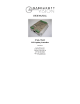
VTR1 fulfils your requirements. See the back cover for other Gardasoft Vision strobe lights.
Mount the VTR1 as described in Section 4. Connect the VTR1 up to a supply as described in
Connections (Section 5). Set up the VTR1 for the desired operation as described in Configuration
Commands (Section 9).
Visit www.gardasoft.com for application notes on this product. There is also a Support page
which has information on troubleshooting problems.
2.1
Summary of Features
Throughout this manual, references to the VTR1 refer to all variants in the VTR1 range unless
otherwise stated. The convention for the part number is:
VTR1-mm-www-aa-ccc
where:
mm
www
aa
ccc
-T06
-T07
M for master only, MS for master/slave pair
Wavelength of light in nanometres: 740, 850, 940, WHITE
Beam angle in degrees: 12 or 30
Communications: ETH, RS232
Optional suffix for trigger input option
Optional suffix for trigger output option