1
WI-I/O 9-K v1.9
5 DIAGNOSTICS AND TESTING
5.1 System Problems
Most problems relate to incorrect configuration, or radio path problems. Before installing the
WI-I/O K module, "bench-test" its operation with the receiving WI-I/O 9-x module alongside. If
the WI-I/O K does not work properly in this test, it will not work properly installed. If problems
are found, check the configuration.
If the bench-test is successful, however problems are experienced after installation, check the
radio path (refer to the WI-I/O 9-x User Manual for radio path testing).
The WI-I/O K provides the following diagnostic features which will help to identify problems.
5.2 LED Indicators
Normally the green OK LED on the front panel will flash briefly every 10 seconds. When the
OK LED extinguishes a sleepmode state is indicated conserving the WI-I/O K'
s battery power. If
the OK LED does not flash, a flat battery condition or an internal failure may exist. If the WII/O K module is located outside, then it will be difficult to see when the LED indicators are on.
Remove the front lid of the WI-I/O K to see the LED'
s better.
The yellow TX LED will flash whenever a radio transmission occurs.
Table of indicator conditions
INDICATOR
CONDITION
MEANING
OK LED ON
Flashes briefly
Normal Operation
OK LED OFF
Continuously
Supply fail or Battery voltage low
CPU failure
OK LED ON
Continuously
Analog loop on
Configuration cable connected
TX LED ON
Flashes briefly
Radio transmitting
5.3 Diagnostic Features
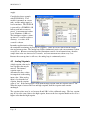
The configuration software provides some diagnostic features to help identify problems. To use
these features, connect the WI-I/O K to a PC using a RS232 cable and run the configuration
software. The OK LED will light continuously once the module is in configuration mode.
Page 46