1
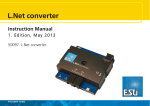
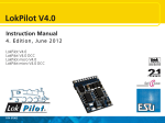
User Manual
IB Control
HOTLINE
If you don’t know where to turn for help
We are here for you
Mon-Tue-Thu-Fri 14:00-16:00
Wednesday 16:00-18:00
02045-858327
Before you call us,
have the following handy:
Serial number of your device,
Version number of the System Software
and this Manual.
2
IB Control
Table of Contents
1. General Description........................................................ 4
1.1 Description ................................................................ 4
1.2 Connection................................................................ 4
1.3 Technical Data .......................................................... 4
2. Display, Keys and Menus............................................... 5
2.1 Operating Elements .................................................. 5
2.2 The Display ............................................................... 6
2.3 Key functions ............................................................ 6
2.4 The Menus ................................................................ 7
3. Basic Settings ................................................................. 9
3.1 Menu structure .......................................................... 9
3.2 Menu “User Interface” ............................................... 9
3.2.1 Loco Speed display ...................................................... 9
3.2.2 Speed knobs............................................................... 10
3.3 Menu “Language”.................................................... 11
3.4 Menu “Display” ........................................................ 11
3.14 Menu “Special Option” .......................................... 12
3.15 Menu “Software-Version” ...................................... 13
4. The Control Panel ......................................................... 14
4.1 Control elements ..................................................... 14
4.2 Loco addresses....................................................... 15
4.2.1 Selecting a locomotive................................................ 15
4.2.2 Using the address memory......................................... 16
4.3 The speed knob (throttle) ........................................ 17
4.4 Lights and extended functions ................................ 18
4.5 Consisting (Multi-traction) ....................................... 19
4.5.1 Setting up a consist .................................................... 19
4.5.2 Consist behaviour ....................................................... 19
4.7.3 Releasing a Consist.................................................... 20
4.5.4 Storing a Consist ........................................................ 20
4.8 Controlling function decoders.................................. 20
4.7 Operation the FRED Hand controller ...................... 21
5. The Keyboard Mode ..................................................... 22
5.1 Selecting the Keyboard mode ................................. 22
5.2 Using the Keyboard................................................. 22
5.4 Keyboard Table mode............................................. 24
6. The Memo Mode (Route control) ................................. 25
6.1 Selecting Route Groups .......................................... 25
6.2 Switching Routes .................................................... 26
7. The s88 Mode ................................................................ 27
7.1 Operation ................................................................ 27
7.2 Address range......................................................... 27
7.3 Entering s88 Mode .................................................. 28
7.4 Changing the Key assignment ................................ 28
7.5 Showing the State of a Specific Contact ................... 1
8. Software Update ........................................................... 29
9. Error Messages............................................................. 30
All trademarks used are registered by the respective companies.
3
IB Control
1. General Description
1.1 Description
The IB-Control is an Add-on Controller for the Intellibox. It expands
the functionality of the Intellibox by 2 speed controls, Keyboard and
s88 Monitor.
All running and switching functions of the Intellibox are available.
Access to the Programming track and access to the centre are not
possible in all settings.
1.2 Connection
Connection is via the LocoNet socket of the Intellibox. The LocoNet
cables can be up to 100m in length which gives the IB-Control a
large operating radius.
Fig 1.21
The IB-Control has
two identical
LocoNet sockets on
the back
The IB-Control connected to the Intellibox LocoNet T socket (socket
2) using the provided LocoNet cable.
The Intellibox operates with a maximum of 118 speed controllers,
like IB-Control, FRED, or Lokmaus.
NOTE The Intellibox provides a maximum current of 0.5A from the LocoNet
T output. If this maximum current is reached by the connected
devices, additional devices can only be connected when supplied
with additional power, by devices such as our LocoNet Power feed
device (Part No. 63 100)
1.3 Technical Data
Connections
2 LocoNet sockets
Power load on LocoNet
max. 120mA
Measurements
180 x 136 x 80 mm
4
IB Control
2. Display, Keys and Menus
2.1 Operating Elements
LCD-Display with information about decoder format, locomotive
address, speed step and driving direction (outer) and the status of
the currently selected device (middle), e.g. Keyboard indication of
turnout and signal state.
Operating indicator and
Stop and Go Keys
Right Speed control with
function Keys and Loco
Number Key
Left Speed control with
function Keys and
Loco Number Key
Middle Key block with numeric
keys and special keys for Menu
navigation
Menu
Context sensitive option settings.
Mode
Selection between keyboard, route control (note mode), s88Monitor, IRIS mode and Programmer.
Throttle and reversing switch
The throttle control, without end stop, automatically restores the
memorized speed and direction when the locomotive is changed. A
press on the throttle knob will stop the locomotive without inertia
control (= emergency stop) and then changes the driving direction.
Auxiliary function keys f1-f4 and function
To control lights and 8 auxiliary functions
Special lok# key
Awaits the subsequent entry of a 1 to 4 digit locomotive address.
Numeric key block
Numeric keypad and special keys for easy address input, for
switching of turnouts or signals, for programming decoders and for
navigating menus.
5
IB Control
2.2 The Display
The user interface is implemented into a backlit LCD display. The
display is divided in three parts and is designed in order to give the
user a quick and clear view of the available commands.
At both sides the display shows the relevant loco decoder format,
the address, the speed level and the driving direction. In the middle
part the display shows information on the presently active mode;
e.g. the current position of the solenoid devices in "keyboard mode".
The text for menu-driven decoder programming is shown on the
whole screen.
2.3 Key functions
g, s
Switch the digital voltage on (go) and off (stop).
A system reset is performed when s+g are pressed at the
same time for about 2.5 seconds.
:;<=
Toggle the loco extended functions.
Together with the l key f5 to f8 toggle the functions of DCC
decoders (see section 4.4).
fo
Switch the direction-dependent function on and off.
l
Starts the input of a loco address.
Together with the >-A keys, it toggles the f5 to f8 functions of
DCC decoders (see section “Light and Special Functions” in the
chapter “Driving desk”).
See also the function of the C key.
NOTE A change of data format of the selected decoder using the l and
m key combination is only possible from the Intellibox (see the
Intellibox Manual, chapter “Changing data format of a locomotive
decoder” in the chapter “The Control Panel”)
m
Start/end of a context menu (followed by the M key).
M
Scrolls among the control panel modes: keyboard, route control
(Memo Mode) and s88 monitor.
6
IB Control
0-9
Decimal digits
Fig 2.31
The numeric key
pad keys
LR
One menu level (or one column) to the left or to the right
D
Decrements a value by one or goes one menu entry downwards
+
Increments a value by one or goes one menu entry upwards
Builds a consist
Adds a loco to a consist control
E
Confirmation key (enter)
C
Deletes the last entry from the keyboard
Deletes a consist
2.4 The Menus
Fig 2.41
The structure of
the IB-Control
menus
NOTE
2.4.1 Structure and navigation
R One menu level (or one column) to
the right
L One menu level (or one column) to
the left
D One menu entry downwards (from
top to bottom)
+ One menu entry upwards (from
bottom to top)
m ends a context menu and
returns to the normal IB-Control control
mode.
During navigation in the menus the display shows the relevant
messages instead of the status of locomotives and turnouts. All
control functions for locomotives are still active: knobs for speed
and direction change, function keys :-=, f-o keys.
Therefore, during navigation you are still able to control the last
selected locomotives.
7
IB Control
2.4.2 Help in the display
Should a level include further menu levels, then the first character in
the second row of the display will be a ">".
Should the entry be a parameter value, which could be activated or
changed, then the first character in the display will be a "=".
All active entries are indicated with a "*" at the end of the line.
2.4.3 Inputs
Numeric values can be entered using the numeric key pad. The
input position is shown by a blinking character in the display.
The C button clears the last entered digit.
If you want to run "horizontally" among the different levels, use the
R and the L buttons to step between the columns.
8
IB Control
3. Basic Settings
The basic settings of the IB-Control can be changed using this user
friendly menu. All setting will permanently be saved in the
nonvolatile memory of the IB-Control.
It is not possible to access the programming track nor all settings in
the central controller. Press the m and the M buttons one
after the other in order to enter the basic settings menu.
3.1 Menu structure
The Structure of the Basic Settings Menu.
Default value is marked by a star (*).
3.2 Menu “User Interface”
3.2.1 Loco Speed display
The speed of the loco can be displayed in two different ways.
Absolute Speed (default factory setting)
The speed level will directly be displayed using the current
operating level. According to the chosen data format the display will
show numbers in the range 0-14, 0-27, 0-28, 0-31 or 0-126.
Percentage of maximum speed
The speed level will be displayed in percentage of the maximum
speed independently of the current data format.
How to set loco speed display
• Press the m key
• Press the M key
• Scroll with the D key until you read “User Interface”
• Enter the menu with the R key
9
IB Control
• Scroll with the D key until you read “Loc speed display”
• Enter the menu with the R key
• Scroll with the D key until you reach your desired entry
• Select this setting by pressing the E key
• Go back to the main display with the m key
3.2.2 Speed knobs
Here you can choose the style of the speed knob. An AC style knob
or a DC style knob could be chosen.
The default factory setting is the "AC style knob".
The AC style knob
The AC Style mode works like an old-fashioned three rail AC
controller.
Using the AC style, the speed will always be increased while turning
the knob clockwise and will be decreased while turning the knob
counterclockwise. If the max. speed or the speed zero is reached, a
further turn of the knob in the same direction has
Fig 3.21
no effect. The max. speed or the speed zero will
How an
be maintained.
AC style knob
A slight push on to the speed knob will reverse
works
the direction of the loco.
Pushing the speed knob during driving will stop
the loco first (emergency stop). Then the direction will be changed.
Depending on the decoder format, some locos stop immediately
(Märklin, DCC) while other locos stop using their current
deceleration rate (Selectrix).
DC style knob
The DC Style mode works like a DC speed control device for DC
two rail systems.
Using the DC style, turning clockwise, the speed
Fig 3.22
knob, starting from a zero speed level, will increase
How an
the speed of the loco in forward direction. Turning
DC style knob works
the speed knob counterclockwise will decrease the
speed until the zero speed level is reached. A
further turn of the knob will reverse the direction of
the loco and will increase the speed in reverse
direction. If the max. speed level is reached, further turns of the
knob in the same direction will not cause any change. On the other
hand, when speed zero is reached, you will be allowed to change
direction to the locomotive after about half a second. Only after this
pause is a further knob rotation accepted. This feature prevents
unwanted direction changes.
A slight push on the speed knob will stop the loco. Depending on
the decoder format, some locos will stop immediately using a loco
dependent emergency stop (Märklin Motorola, DCC) while other
locos will stop using their current deceleration rate (Selectrix).
10
IB Control
How to change the style of the speed knob
• Press the m key
• Press the M key
• Scroll with the D key until you read “User Interface”
• Enter the menu with the R key
• Scroll with the D key until you read “Speed knobs”
• Enter the menu with the R key
• Scroll with the D key until you reach your desired entry
• Select this setting by pressing the E key
• Go back to the main display with the m key
3.3 Menu “Language”
The languages for the display can be selected here from one of the
following:
German
English
French
Italian
Dutch
Swedish
Spanish
Portuguese
Danish
The default factory setting is "German".
How to change the language of the display
• Press the m key
• Press the M key
• Scroll with the D key until you read “Language”
• Enter the menu with the R key
• Scroll with the D key until you reach your desired entry
• Select this setting by pressing the E key
• Go back to the main display with the m key
3.4 Menu “Display”
The Display menu could be used to adjust the brightness and the
contrast of the LCD.
How to change brightness and contrast of the LCD
• Press the m key
• Press the M key
• Scroll with the D key until you read “Display”
• Enter the menu with the R key
11
IB Control
• Scroll with the D key until you reach your desired entry
• The adjustment can be made using the D and the + keys
• Select this setting by pressing the E key
• Go back to the main display with the m key
IMPORTANT If you leave the menu without using the E key, the old settings will
be restored.
HINT If the display is unreadable because of a wrong setting of the
brightness and/or contrast, you could recall the default factory
settings by switching the main power on while pressing down the +
key at the same time.
3.14 Menu “Special Option”
The IB-Control has various special options which affect its operation
and can differ between Software Versions.
Each special option can be selected and changed using an ID
number. Details of individual special options can be inferred from a
list for the respective software version.
With later software changes a file with the appropriate explanations
is on the update disk.
Method:
• Press m-key
• Press M-key
• Press D-key to scroll to the "Special Option" entry
• Continue with R-key
• Enter special option ID at the first input position after "N."
• Press R-key to move the cursor to the right input position
• Enter the value for the special option
• Press E-key
A “*” in the display indicates that the special option is active
NOTE
• Press m-key to return to running operation
In the change special options menu, if the M-key is pressed
while the input cursor is in the section to the right of the equals sign,
the displayed numerical value is represented in hexadecimal.
This function is used for display only. It can be cancelled by a
further press of the M-key.
12
IB Control
3.15 Menu “Software-Version”
Under this menu option you will find the serial number of your
device and the version number of the system software.
Method:
• Press m-key
• Press M-key
• Press D-key to scroll to the "Software Vers." entry
• Continue with R-key
• The upper line shows the system software version number and
the lower line shows the serial number of the IB-Control
• Press m-key to return to running operation
13
IB Control
4. The Control Panel
Locomotives can be addressed and controlled by means of the
control panel. The IB-Control has two independent control panels,
located left and right of the numeric keypad.
Decoders with different data formats can be controlled
simultaneously.
Use of the control panel is possible even while the device
configuration is being changed.
4.1 Control elements
Fig 4.11
The Front panel of
the IB-Control
Each of the controllers has the following elements:
The s key
Use the s key to switch the digital voltage to the normal track
OFF. The display will show “STOP”. Pressing this key will act on
both control panels.
The g key
Use the g key to switch the digital voltage to the normal track ON.
Pressing this key will act on both control panels.
This key is used by both driving desks.
NOTE You can reset the IB-Control by pressing both the g and s
keys for about two seconds.
The : ; < = keys
These keys control the locomotive’s extended functions, e.g. lights,
sounds, smoke generator.
NOTE If you press l followed by one of the :-= keys, you will be
able to switch the f5 - f8 extended functions of DCC decoders (see
the Intellibox Manual, chapter “Light and Special Options” in the
chapter “The Control Panel”)
f and o key
These two keys switch the locomotive lights on/off.
l key
Starts the input of a locomotive address.
14
IB Control
After completing the locomotive address input, you can change the
decoder protocol. Press [menu] and select the appropriate data
format (protocol).
NOTE If you press l followed by one of the :-= keys, you will be
able to switch the f5 - f8 extended functions of DCC decoders (see
the Intellibox Manual, chapter “Changing data format of a
locomotive decoder” in the chapter “The Control Panel”).
The speed knob (throttle)
Use the knob to change locomotive speed and direction of travel.
Suppose that you have chosen a previously controlled locomotive
with the l key and, given the fact that the knob can rotate
freely, the IB-Control automatically reads the previous operating
level of the locomotive from its memory, and takes control from that
level.
Even if you are in the process of changing an IB-Control parameter
(in configuration mode), you can still control a locomotive with a
speed knob; the ongoing configuring can proceed without problems.
The display
The backlit LCD continuously shows the detailed status of the
currently controlled locomotives: the address, the protocol (data
format), the operating level and the direction of travel are shown in
the left and right sections of the display.
The data format used, locomotive address, vehicle speed and
driving direction of the currently controlled vehicle are displayed at
the sides, for each control panel.
The centre indicates the selected operating mode.
4.2 Loco addresses
Each locomotive in a digital system can be controlled by means of
an “address” (a combination of digits that uniquely identifies the
locomotive’s decoder).
Each decoder has its own address. An address should identify one,
and only one, locomotive.
Normally, a locomotive decoder is controlled by only one of the two
control panels. However, it is possible to control the same decoder
with both throttles.
4.2.1 Selecting a locomotive
In order to control a locomotive with the IB-Control you must select
its address.
To select a locomotive address, first press l-key. The display
will show a blinking cursor in one of the address fields, prompting
you to input a value.
15
IB Control
There are two methods to do it:
Input via the numeric keyboard
• Press the l-key
• Input the digits that form the whole address with the numeric
keypad
• Terminate address input:
- press the E key,
- press any other key in the control panel:
f o : ; < = l,
- turn the knob (throttle),
- press the knob to induce a change of direction.
Address selection using the speed knob
• Press the l-key
• Turn the knob to change the address, clockwise to increase the
value, counter clockwise to decrease it.
• Terminate address input:
- press the E key,
- press any other key in the control panel:
f o : ; < = l,
- press the knob to induce a change of direction.
HINT Use the C key to erase wrong entries, one digit at a time. If you
cancel the whole address, a further press of the C key will recall
the previous address.
NOTE Should you try to take control of a locomotive which is already being
controlled by another knob, the IB-Control will show the message
"Loco used by another controller!" After this message you can
control the relevant locomotive using both manual controllers (the
external or the internal ones).
4.2.2 Using the address memory
The IB-Control stores the address of the last locomotive controlled
by each of the control panels in its memory.
It is possible to recall this address:
• Press l
• Press D
The last valid address is displayed and is ready to be used.
4.2.3 Releasing a Loco address
To release the control of a locomotive address (the released
locomotive can then be taken over by a manual controller without
selection keypad, e.g. FRED by Uhlenbrock or BT-2 by Digitrax),
use the following procedure:
Single locomotive
• Press l
16
IB Control
• Cancel the whole address with the C key
• Press l
Consist
• Press l
• Press any number key (0-9)
• Cancel the whole address with the C key
• Press l Individual locomotive
4.3 The speed knob (throttle)
Fig 4.31
How an
AC style knob
works
Fig 4.32
How an
DC style knob
works
The speed knob serves to change locomotive speed and driving
direction. The IB-Control has rotary knobs without end stops, to
which it automatically restores the saved speed of a locomotive,
when it is reselected by a locomotive change.
The speed knob has two different operating modes:
The AC style knob
The AC Style mode works like an old-fashioned three rail AC
controller.
Using the AC style, the speed will always be increased while turning
the knob clockwise and will be decreased while turning the knob
counterclockwise. If the max. speed or the speed
zero is reached, a further turn of the knob in the
same direction has no effect. The max. speed or
the speed zero will be maintained.
A slight push on the speed knob will reverse the
direction of the loco.
Pushing the speed knob while it is running will stop the loco first
(emergency stop). Then the direction will change.
Depending on the decoder format, some locos stop immediately
(Märklin, DCC) while other locos stop using their current
deceleration rate (Selectrix).
DC style knob
The DC Style mode works like a DC speed control device for DC
two-rail systems.
Using the DC style, turning the speed knob
clockwise starting from a zero speed level will
increase the speed of the loco in forward direction.
Turning the speed knob counterclockwise will
decrease the speed until the zero speed level is
reached. A further turn of the knob will reverse the
direction of the loco and will increase the speed in
reverse direction. If the max. speed level is reached, further turns of
the knob in the same direction will not cause any change. On the
other hand, when speed zero is reached, you can change direction
to the locomotive only after about half a second. Only after this
17
IB Control
pause is a further knob rotation accepted. This feature prevents
unwanted direction changes.
A slight push on to the speed knob will stop the loco. Depending on
the decoder format some locos will stop immediately by a loco
dependent emergency stop (DCC) while other locos will stop using
their current deceleration rate (Märklin Motorola, Selectrix).
Pre-setting
The IB-Control is shipped with the AC style mode active. Changes
can be made in the Basic Settings menu (see chapter “User
Interface/Speed Knobs”).
4.4 Lights and extended functions
The f key and the extended function keys :-= control
the lights and the locomotive decoder extended function outputs.
f
Switches the direction-dependent auxiliary function (usually the
locomotive lights) ON.
o
Switches the direction dependent auxiliary function OFF.
If you press the o key, the auxiliary function switches on briefly,
even if it was not previously switched on with the f key.
Extended functions
Press one of the :-= keys to control the relevant extended
function.
Each key press toggles the relevant decoder output, from “off” to
“on”, and vice-versa.
Additional functions
The l key used in combination with the :-= keys, controls
the f5 to f8 functions of 8-function decoders. The l key must be
pressed just before (not simultaneously with) the :-= keys.
The following key combinations are valid:
- l and :control function f5
- l and ;control function f6
- l and <control function f7
- l and =control function f8.
During the control of an extended function the display will show its
status (1=on, 0=off).
NOTE The function status is displayed for about 2 seconds. During this
period, you can change the status of another function without
having to press l first.
18
IB Control
4.5 Consisting (Multi-traction)
The IB-Control is able to control several locomotives with a single
throttle. This is called “consisting”. A consist can be composed of a
maximum of 4 locomotives. Each locomotive can be introduced in a
consist using either its “normal” address or its virtual address.
The IB-Control can control a maximum of eight consists.
4.5.1 Setting up a consist
• Press the l-key
• Enter the locomotive address
• Press the E-key
• Press the l-key
• Enter the 2
nd
locomotive address to add to the locomotive.
• Press the +-key to add a further locomotive.
• End the entry and return to driving mode by pressing the E-key
• Press m-key to return to driving without change.
All locomotives in the consist can now be controlled together under
the address of the base locomotive.
Locomotives can similarly be added to an existing consist.
When controlling a consist, the symbol which is normally reserved
for the decoder type is substituted by a “+”. On its right side you will
find the base locomotive address. In the final version of the
Intellibox software, the speed of the consist will be displayed as a
percentage of the maximum speed.
4.5.2 Consist behaviour
After having created a consist, you can control all the locomotives
using the base locomotive address.
If you try to recall the address of a “consisted” locomotive, the
display will show “MUL” in the speed field and no direction will be
indicated. The direction of this locomotive can however be changed
so all of the locomotives in the consist can be set to the same
direction at the start.
19
IB Control
NOTE This feature allows one to correct, if necessary, the direction of
travel of a locomotive which has just been added to the consist,
without the need to remove the locomotive from the consist.
Special functions (function F1 to F4) of the coupled locomotives in
the consist can be individually controlled under their own address
independently of the base locomotive.
If the consist includes locomotives with different numbers of
operating levels, the Intellibox will operate the consist using the
number of operating levels of the base locomotive.
If, for instance, a decoder with 28 speed steps is used together with
a decoder with 14 speed steps the controller change the 28 step
decoder with every step of the speed control and the 14 step
decoder at every second step of the control knob. It is therefore
recommended that the locomotive with the least number of speed
steps is used as the base locomotive of the consist.
IMPORTANT For trouble free operation of a number of locomotives in a consist it
is vital that all the locomotives are set to the same minimum and
maximum speeds.
NOTE The maximum and minimum operating levels can be configured in
the decoder itself.
Please refer to each decoder’s operating manual.
4.7.3 Releasing a Consist
A consist can be released either completely or by uncoupling one
locomotive at a time.
Method:
• Press the l-key
• Press the C-key
• Scroll to the desired entry with the D-key
NOTE
• Press the E-key to confirm the selection
While you can add locomotives to aconsist through their virtual
address, only the real address is shown while removing single
locomotives from a consist.
4.5.4 Storing a Consist
Consists can be stored in the Intellibox’s non-volatile memory when
the Intellibox Start option is set to “auto” (see the Intellibox Manual
chapter “Loc start mode”)
4.8 Controlling function decoders
Function decoders are used to control models with special electric
or electronic features, or when more functions than the locomotive
decoder has need to be switched.
20
IB Control
Function decoders are controlled using the : to = keys of the
controller. Together with the l-key a number of DCC decoders
can use f5 to f8 (see “Lights and extended functions”)
In Motorola data format Keys : to = can only control Motorola
function decoders in the old Motorola data format.
In locomotive decoders using new and old Motorola formats these
keys have no effect.
NOTE The data format of the function decoder can only be selected with
the Intellibox using the instructions in the Intellibox Manual (see the
section “Changing data format of a locomotive decoder” in the
chapter “The Control Panel”).
4.7 Operating the FRED Hand controller
The FRED hand controller (Part No. 66 000) can be connected to
the LocoNet socket on the IB-Control.
The assignment and freeing of a locomotive address
assignment of the individual hand controller numbers
the control centre. The deletion of individual FRED’s
the “Hand control” menu under the “Basic Settings”
Intellibox.
21
and also the
is done from
is done from
menu of the
IB Control
5. The Keyboard Mode
In a digital system turnouts and signals can be controlled by
decoders. Just like with locomotives, these are assigned individual
addresses to identify them.
The IB-Control switches turnout and switch decoders in various data
formats, the Motorola and DCC data formats. Decoders of both
formats can be operated side-by-side.
NOTE A number of turnout decoders from Märklin, Viessmann and
Modeltreno for the Motorola format control four Solenoids. The
decoder address is set up with a DIP switch. This address is not
identical to the solenoid address of the connected turnouts.
A table to determine the DIP switch setting for a particular turnout
address as well as the allocation to the Märklin keyboards can be
found in the Appendix of the Intellibox Manual.
With Uhlenbrock solenoid and switch decoders the assignment of
the decoder address is done by pressing the programming key on
the decoder followed by pressing the desired key on the keyboard.
The devices have an address range up to 2048 and can be
operated in either DCC or Motorola data format.
In the Basic Settings of the Intellibox the data format for the
decoders can be selected (see the Intellibox Manual, section
“Accessory (decoder) setting” in chapter “Basic Settings” ).
5.1 Selecting the Keyboard mode
The IB-Control has several operating modes. Currently these are:
keyboard, route control, and s88 monitor. With each press of the
M-key the operating mode is changed and shortly after is
indicated in the display. Press the M-key as often as needed
until “Keyboard” is displayed.
The centre of the display changes to match the selected mode.
5.2 Using the Keyboard
In “Keyboard” mode, the numeric keypad is used to control
electromagnetic (solenoid) devices (turnouts, signals, relays). At
power up, you can control, without any additional configuration, the
first 8 devices.
Fig. 5.21
The keypad (in
Keyboard mode)
and the numbering
of key pairs
Switching is accomplished with the red and green keys. The display
will show “R” or “G” when you press, respectively, a red or a green
22
IB Control
key. Additionally, the sequential address of the controlled device is
also displayed.
Normally, the display will show the current status of the Keyboard:
If the last key to be pressed was a red one, its rectangular marker
will be in the “up” position (see figure, positions 1, 7, 8 of the
available 8, 4 in each line). If, however, the last key to be pressed
was a green one, its marker will be in the “down” position.
5.3 Selection of the Keyboard address
After the IB-Control is switch on the red/green pairs numbered 1 to 8
are assigned to devices from 1 to 8.
Fig. 5.31
The keypad (in
Keyboard mode) and
the numbering of key
pairs
This assignment can be changed by giving the first key pair a new
address.
Method:
• Press the M-key as often as needed until “Keyboard” is
displayed
• Press the m-key.
• The address associated with the first pair of keys (1 and 4) will
blink in the first column of the second line. The second column
shows the address controlled by the 8th pair of keys.
Directly enter the address of the first key pair using the numeric
keys. Using the R and L the value can be increased or
decreased in steps of 8.
If you change the address for the first pair of keys, the address for
the 8th pair will also change automatically.
This will be the display if the first pair of keys has an address of
17:
• Press the E-key to confirm the entry
• Press the m-key to return to driving
23
IB Control
Solenoid decoders in Motorola format have an address range 1-320
available. For DCC decoders the address range is 1-2040.
5.4 Keyboard Table mode
When in Keyboard mode, if the address of the solenoid device
controlled by the first pair of keys ([1] and [4]) is changed, the
remaining key pair are automatically assigned the following solenoid
devices.
In Keyboard Table mode on the other hand it is also possible to
assign a particular solenoid device to a particular key pair.
The table is selected by entering the "0" (zero) for first key pair. The
display will confirm the activation of the “Table” mode with the
following indication:
Using the “Special Options” menu in “Basic Settings” the key pairs
can have the desired address assigned to them. A list of special
options can be found in the Intellibox Manual Appendix.
24
IB Control
6. The Memo Mode (Route control)
In a digital system, turnouts and signals which are equipped with
switch or solenoid decoders, can be individually switched using
appropriate input devices.
With the Memo mode it is possible to combine the Intellibox turnouts
and signals into a group or a route and switch them with a single
key press, without the need for additional devices.
In this mode the 16 keys in the numeric key block form a group of
16 routes. 3 different groups can be called making a total of 48
routes available.
The Memo mode for the Intellibox and IB-Control are available in
software versions from 1.203. The routes must be installed in the
Intellibox.
Routes can be switches by all IB-Controls connected to the
Intellibox. The programming of routes and speed setting for each
entry can only be done from the Intellibox.
6.1 Selecting Route Groups
Three different groups of 16 routes can be defined. The currently
active group number is indicated in the display.
A change of the route group is possible with the following
procedure.
Method:
• Press M-key repeatedly until "Memo mode" appears in the
display.
• Press m-key
• In the left part of the display, after "Gr. - Nr.", enter the number of
the desired group of routes (1-3)
• Press the E-key to return to the normal driving operation.
25
IB Control
6.2 Switching Routes
In memo mode a programmed route can be switched with each
individual key of the numeric block.
Press M key repeatedly, until the display indicates "Memo
mode". Now the keys of the middle key field correspond to routes 1
to 16.
Fig. 6.21
The keypad and the
numbering of key
pairs in Memo Mode
The pertinent route is switched by pressing one of these keys.
The display shows the group and route number with a rotating bar
between them. This is shown until all switching of the route is
processed by the Intellibox.
If nothing is displayed then no route is assigned to that key in the
selected group.
26
IB Control
7. The s88 Mode
If a model railway layout is to be automated then information is
required on the whereabouts of trains in track sections.
Feedback modules monitor such track sections and report the
status “a train is here” or “there is no train here”. A route control or
computer program can use this feedback to switch turnouts and
signals accordingly in order to control the progress of the trains.
7.1 Operation
The s88 Mode should really be called the feedback mode. In the
Intellibox feedback is possible via the s88 bus and via the LocoNetBus. When the Intellibox was first introduced feedback via the s88Bus was the norm, hence the name. Since then LocoNet feedback
modules have also been introduced.
Whereas s88 compatible modules must be polled by the centre and
the Intellibox then passes the feedback to the LocoNet, the LocoNet
feedback modules independently send the “occupied” and “vacant”
signals to devices connected to the LocoNet. This not only frees
the controller but is also faster and more reliable.
As opposed to other control centers the Intellibox stores the s88
feedback signals internally. Connected computers need then only
request the internal information which then informs if a change has
occurred. So the Intellibox can respond as rapidly as possible, it
needs to know how many s88 feedback modules are connected.
The number can be entered in the basic settings menu of the
Intellibox (s88 Setting).
If eventually LocoNet feedback units are used the number of s88
modules can be set to zero in the s88 Module basic settings menu
of the Intellibox (s88 Setting).
7.2 Address range
The Intellibox can support a total of 128 feedback modules, each
with 19 inputs, giving a total of 2048 possible inputs.
When using LocoNet feedback modules, each device’s contact
address is programmed directly into the device. The feedback
inputs can have an address from 1 to 2048.
When s88 compatible feedback modules are used the contact
address for a feedback input is determined by the order of the
feedback modules in the s88-Bus. The s88 feedback module which
is considered by the controller to be the first connected has contact
addresses 1 to 16, the next has addresses 17 to 32 etc. As the
maximum number of s88 feedback modules that can be connected
to the Intellibox is 31, the highest valid address these modules is
address 496.
If LocoNet feedback modules and s88 feedback modules are mixed
in a system care must be taken to ensure that the contact
27
IB Control
addresses used for the LocoNet feedback modules come after the
addresses used by the s88 feedback modules. In this case we
recommend that range 1 to 496 be used for s88 feedback modules
and addresses 497 to 2048 be reserved for the LocoNet feedback
modules.
7.3 Entering s88 Mode
Press the M-key repeatedly to scroll until the display reads
“s88 Mode”. The display changes to match the selected mode.
In s88 mode the state of the connected feedback module is
displayed.
7.4 Changing the Key assignment
After turning on in s88 Mode the module with address 1 is always
displayed. To display other modules the module address must be
changed from the Intellibox.
After pressing the m-key the display will show:
With the numeric key the module address can then be changed.
Valid addresses are 1 to 128. With the m-key you can then
return to normal driving operation.
7.5 Showing the State of a Specific Contact
Fig. 7.51
The keypad and the
numbering of key
pairs in s88 Mode
In s88 Mode when one of the 16 keys of the
middle area is pressed, the corresponding
input of the connected feedback module will
be displayed by ‘0’ or ‘1’.
28
IB Control
8. Software Update
You can update the System software of the IB-Control anytime via
the internal Computer Interface of the Intellibox.
Hardware preparation
In addition to the IB-Control you require: 1 Intellibox, 1 transformer
18V, 1 power cable, 1 Interface cable, 1 LocoNet cable
Connect the Intellibox to power via the transformer
Connect the Intellibox to the PC Interface cable to the serial port of
the computer
Connect the IB-Control using a LocoNet cable to the LocoNet Tsocket of the Intellibox.
IMPORTANT Only one IB-Control is allowed to be connected to the Intellibox.
During updating no other LocoNet devices are allowed to be
connected.
The device does not need to be opened!
Software Preparation
You will either receive a diskette with the new software from your
supplier or you can download the file(s) from the Internet:
www.uhlenbrock.de
NOTE The update program is a pure DOS program and therefore cannot
be run on an Apple Macintosh.
How to update the software
• Connect the serial cable between the Intellibox and a PC serial
(COM) port.
• Switch off the Intellibox for about 10 seconds. Switch it back on
and wait for the completion of the initialization procedure.
• Run the application ‘bupdate.exe’ on your PC and follow the
onscreen instructions.
Checking the software version
With the ‘Software vers.’ menu in the system’s parameters, you can
check the software version of your Intellibox.
• Press the m-key
• Press the M-key
• Press the D key until ‘Software vers.’ is displayed
• Enter this menu by pressing R
• The top line displays the system’s software version number, while
the bottom line shows the Intellibox serial number.
• Press the m-key to return to the main screen.
29
IB Control
9. Error Messages
In case of error during normal Intellibox operation, its power supply
is immediately interrupted, the red LED above the [stop] key starts
blinking and the display shows an error message.
Short-circuit on the main track.
Short-circuit on a section controlled by a
Booster.
Short-circuit on the C/D lines booster or
LocoNet outputs.
Short-circuit between normal track and
programming track outputs, the Lenz
Booster output (C/D line) or the LocoNet
B output (power overload)
Short-circuit on the Lokmaus bus.
From continuously using the Intellibox at
its maximum rated output. To avoid
permanent damage to its electronic
circuitry, switch off the device until it has
returned to normal temperature
The track has a voltage that is not from
the Intellibox.
As soon as the error has been corrected and/or the temperature
decreases, you can power your layout again by pressing the g
key.
30
IB Control
Product Overview
60 500
60 502
60 506
60 540
60 560
61 010
61 020
61 030
61 040
62 020
62 030
62 060
62 120
62 220
62 250
65 000
65 002
65 006
65 010
65 400
65 600
65 800
66 000
67 200
67 500
67 600
70 400
71 500
71 621
71 651
71 700
74 400
74 420
75 000
75 100
75 200
75 320
75 400
75 420
75 520
75 530
75 900
IB Manual German
IB Manual English
IB Manual Dutch
IB-Control Manual German
Power3 Manual German
PC Interface cable
Adapter Intellibox/Control Unit
Adapter Intellibox/=Booster
Replacement plug set
LocoNet replacement cable (2,15 m, 2 plug)
LocoNet replacement spiral cable (approx. 3 m, 2 plug )
LocoNet long connecting cable (6 m, 2 plug )
LocoNet extension (2,15 m, 1 plug , 1 double socket)
LocoNet coupling (2 sockets)
LocoNet distributor (20 cm, 1 plug ,1 5-fach socket )
Intellibox, with German Manual
Intellibox, with English Manual
Intellibox, with Dutch Manual
Route control, Upgrade for the Intellibox
IB-Control, Add-on control device for the Intellibox
Power 3, Booster with reversing loop or DCC brake generator
IB-Switch, for switching of turnouts and routes
FRED, digital Hand controller
Solenoid decoder MD2
Switch decoder SD1
Switch decoder SD2
Decoder Manual, new items Summer 2001
Motor EMI kit
5, 8-pole NEM 652 sockets
5, 8-pole NEM 652 sockets
Digital switch
DCC locomotive decoder for DC motors
DCC locomotive decoder for DC motors with plug
Motorola locomotive decoder AnDi for AC/DC motors
Motorola locomotive decoder for AC/DC motors (Märklin)
Motorola locomotive decoder for AC/DC motors with load regulation
Motorola locomotive decoder AnDi for DC motors with plug
Motorola locomotive decoder for DC motors
Motorola locomotive decoder for DC motors with plug
Motorola locomotive decoder for DC motors with load regulation and plug
Motorola locomotive decoder for Faulhaber motors with load regulation
Motorola Function decoder
Our catalog is available from your distributor
or direct from us by sending 10,- DM in postage stamps.
All our products have a warranty of two years.
We reserve the right to change data in this booklet at anytime.
31