1
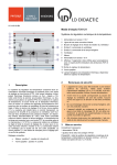
03/15-W10-Wei Instruction Manual 740 306 1 2 3 4 5 6 7 8 9 10 11 12 13 14 15 16 17 18 19 20 Voltage Supply and Voltage Conduit Terminal 30 Voltage Supply and Voltage Conduit Terminal 15 Display Input Signal Selector Switch Connection of the Preheating Indicator Light (La) Input Signal Measurement Bridging Plug Connection of the Battery, Positive USB Socket Diagnostic Signal Output Ground Connection of Terminal 15 (protected) Current Measuring Shunts (1 – 4) Connection of the Battery, Negative View Port for the Glow Plug Q10 Bore for the Temperature Sensor View Port Q12 Viewing Window Q13 Connection of the Preheating Indicator Light Output Pressure Signal Glow Plug Q13 (with Pressure Sensor) Diesel Quick Start System 21 22 23 24 25 26 27 28 29 30 31 1 Glow Plug Q12 Glow Plug Q11 Glow Plug Q10 Measurement Points for the Glow Plugs (1 – 4) Fuse START / STOP Button Operation LED Multifunction Adjustment Knob MODE Button Temperature Selection LED Pulse Width Selection LED Description The diesel quick start system consists of the following components: Motor control unit substitute Electronic glow plug control unit Instant start glow plug Data interface 740 306 Diesel Quick Start System The glow plugs are actuated with pulse width modulation and phase shift and the function of the glow relay is replaced by electronic amplifiers in the glow plug control unit. 3 instant start glow plugs as well as an instant start glow plug with pressure measurement (PSG). Each of the four glow plugs is capable of handling the diagnosis on its own. The control unit is used in vehicles of the VAG Group for 4- and 6-cylinder engines. It is based on an electronic circuit (IC) such as the L9524C from STMicroelectronics. When the following informative instruction manual was prepared, the English data sheet can be viewed at http://www.st.com/web/en/resource/ technical/document/ datasheet/CD00134658.pdf. Many of the specifications and descriptions can be applied to the system used here. The following operating modes can be studied: 2 Preheating Starting Emergency heating Scope of Delivery 1 1 TPS unit USB Cable Page 2/6 4 Start-up Also required: 1 Car Battery 12 V 1 Battery Connection Kit 1 Set of Connection Leads I 1 Set of Safety Bridging Plugs 738 04/044 734 043 738 05 500 59 Connect the positive pole of the battery using the positive terminal and the red connection cable (6 mm²) with Positive Connection 7. Insert the 4 mm safety bridging plug in Positions 6, 11, and 24. Connect the connection terminal 30 (1) with the permanent positive terminal of the battery. Connect the negative pole of the battery using the negative terminal and the black connection cable (6 mm²) with Negative Connection 13. Result: The device performs a self-test. For this purpose, it also briefly switches on the LEDs and the display. This is not a malfunction! The test takes approx. 2 seconds. The device is then ready for use. The display will show "1.5." Connect the device to Ignition Switch 738 10 and turn the ignition on. The device carries out one glow actuation for testing. Description of Components 1 – 31 3 Safety Instructions The devices are appropriate for dry, interior use only! Do not operate the devices if they have any visible damage. Only use safety bridging plugs and intact safety connection leads! The device should only be used for training purposes. Installation in an actual vehicle is prohibited! Be sure to use only genuine replacement parts for any necessary repairs. Make sure that there is a very secure, direct battery connection! Caution: HOT! During continuous operation, the surface of the glow plug block can reach 80 °C (176 °F)! The openings on the glow plugs Q10 through Q12 are provided only for observations. Do not insert anything into them! The device complies with the current EMC directives regarding spurious emissions. The glow plugs must not be supplied with external voltage! To protect the glow plugs, the maximum switch-on pulse width was limited to 36 %. 1 2 3 Connection Terminal 30 (permanent positive terminal) to transmit to other TPS devices on the right side and to supply the internal electronics. Connection Terminal 15 (Connected positive terminal) to transmit to other TPS devices on the right side and to supply the glow plug control unit. Two-digit, 7-segment, multi-function display to display the following sizes: Temperature: Display of -19 to +85 °C or 2 to 189 °F. When set to "°F", only the last two digits are displayed for values > 99 °F. An additional period to the right of it indicates that it is for a value > 99 °F. Pulse width: Display of the pulse width in % from 6 % to 36 %. Operation mode: Display of the operation mode. It can be adjusted as follows: Terminal 15 Display: 1.5. Terminal 50 Display: 5.0. Door control Display: d.o. Seat control Display: S.E. Seat belt buckle control Display: b.o. When Terminal 15 is selected, the preheating process is activated by turning on Terminal 15 and is stopped by turning off Terminal 15. Also, pressing Pushbutton 16 cancels the preheating process. When Terminal 50 is selected, the preheating process is started or cancelled at temperatures of < 5 °C and pulse widths of < 10 % by pressing Pushbutton 26. Without manual cancellation, it stops automatically after the calculated time. When the Door Control is selected, the preheating process is started or cancelled at temperatures of < 25 °C and pulse widths of < 10 % by pressing Pushbutton LD DIDACTIC GMBH Leyboldstr. 1 D-50354 Hürth Phone (02233) 604-0 Fax (02233) 604-222 e-mail: [email protected] by LD DIDACTIC www.ld-didactic.com Printed in the Federal Republic of Germany Technical alterations reserved Page 3/6 4 5 6 7 8 9 10 26. Without manual cancellation, it stops automatically after the calculated time. When the Seat Control is selected, the preheating process is started or cancelled at temperatures of < 25 °C and pulse widths of < 10 % by pressing Pushbutton 26. Without manual cancellation, it stops automatically after the calculated time. When the Seat Belt Buckle Control is selected, the preheating process is started or cancelled at temperatures of < 25 °C and pulse widths of < 10 % by pressing Pushbutton 26. Without manual cancellation, it stops automatically after the calculated time. Fault: Display of the activated faults from F0 to F5. Temperature Units: The selected units will be shown to display the temperature in °C or °F. Change over between an external control signal (for example, from an original motor control unit) via the rear 7-pin connector or the control panel with the operating elements 26 - 31. "La" output for connecting a Heating Indicator Light (for example, from 738 151) The preheating status is displayed at temperatures below + 5 °C (45 °F) as continuously lit. Additionally, a fault is indicated by a flashing indicator light until the next time the ignition is turned off. The signal is transmitted to the right side of the device, Socket 18. Thus, the indicator light unit can be placed to the left or to the right. Measurement sockets for measuring the control signal and for simulating faults for example through the Fault Simulation Bridging Plugs 500 593. Power connection for supply the glow plugs. The red 6² mm cable is connected here coming out of the Lead Set 738 05 from the positive pole on the car battery. This lead is internally protected once more on a 40 amp safety fuse. This is where a PC with an MS Windows operating system can be connected to run the corresponding diagnostic software. After the first time it is connected, a driver is installed for the device so that it is known to the computer. New firmware can be transferred to the device via the diagnostic software. The current version of the software can be found at www.ld-didactic.de. This is where the diagnostic signal can be measured, which provides Control Unit J179 for the motor control unit in the event of a fault. The signal has a resting level of 3.3 V and emits an 8-bit word with the start bit (low) and the stop bit (high). The following information is included: Bit 1: Fault Glow Plug 1 Bit 2: Fault Glow Plug 2 Bit 3: Fault Glow Plug 3 Bit 4: Fault Glow Plug 4 Bit 7: Fault Short-circuit to Ground (high) Fault Interruption (low) A bit is tBit = 32 ms long, thus the total length of the 10bit word results in 320 ms. The subsequent pause is 680 ms so that a total cycle time of exactly 1 second results. Short-circuit to ground (Terminal 31) to transmit to other TPS devices on the right side and to supply the internal electronics. 740 306 Diesel Quick Start System 11 Measurement sockets for measuring the signal from Terminal 15 and for simulating faults for example through the Fault Simulation Bridging Plugs 500 593. 12 4 Current sensing resistors (shunts) for indirect measurement of the glow plug current. The voltage drop for each glow plug can be measured here at a low resistance and thus the individual currents are calculated. No voltage may be applied to any of the sockets! 13 Power connection for supply the glow plugs. The black 6² mm cable is connected here coming out of the Lead Set 738 05 from the negative pole on the car battery. 14 – 17 Caution: During continuous operation at the maximum heating time, the assembly block of the glow plugs can achieve a surface temperature of 80 °C (176 °F). 14 View port for observing the tip of Glow Plug Q10. The opening is as small as it is so that reaching into it is not possible. No objects should be instered into this opening, since the glow plug could otherwise be destroyed! 15 Bore for inserting the temperature sensor. The tip of the temperature sensor thereby contacts the glow plug. Thus, the heating rate and the temperature of Glow Plug Q11 can be measured. Over this is a view port for observing the glow plug (the tip is not visible here!) No objects should be instered into this opening, since the glow plug could otherwise be destroyed! 16 View port for observing the tip of Glow Plug Q12. The opening is as small as it is so that reaching into it is not possible. No objects should be instered into this opening, since the glow plug could otherwise be destroyed! 17 Viewing window for observing the tip of Pressure Measuring Glow Plug Q13. The chamber is pressure sealed, so that the heating of the glow plug tip causes an increase in the pressure of the trapped air. This signal can be measured at 19. The safety glass must not be touched during and shortly after the preheating process. Risk of burning! 18 "La" output coming to connect a heating indicator light (for example, from 738 151) from Socket 5 (see Point 5). Output of a voltage signal for display of the pressure measured in Pressure Chamber 17. Here, 10 V corresponds to one MPa. The voltage range is between 0 and 10 V. Connection of the 4-pin, original multi-function plug to Pressure Sensing Glow Plug Q13. Connection of the 1-pin original plug to Glow Plug Q12. Connection of the 1-pin original plug to Glow Plug Q11. Connection of the 1-pin original plug to Glow Plug Q10. Measurement sockets for the glow plug actuation signal of Q10 to Q13. Voltage cannot be applied here. 19 20 21 22 23 24 25 Protection of Control Unit J179 via a 5A mini blade fuse. Only replacement fuses of the same type from Replacement Fuse Set 689 0808 should be used! 26 START / STOP Pushbutton for starting and stopping the heating process. Once the heating process is started, if it is not manually stopped by pressing this pushbutton, it will be automatically terminated after the calculated time. This prevents the glow plugs from overheating. 740 306 Diesel Quick Start System Pressing and holding the pushbutton switches the temperature display between °C and °F. 27 This LED indicates that the heating process is active with a white light. Subsequently it indicates a delay before the next glowstart with a red light. This can be started only when the LED turns off again. 28 Multifunctional knob for adjusting the temperature, pulse width, fault number, operation mode, or temperature unit. Turning it left reduces the numerical values by 1 and turning it right increases them. 29 MODE pushbutton for changing over the display in Display 3 between temperature, duty cycle, and operation mode. With the Temperature Display, LED 30 lights up permanently as well; with the Pulse Width Display, LED 31 lights up permanently as well; and with the Operation Mode Display, both LED 30 and LED 31 light up permanently as well. If the pushbutton is pressed and held, the LED will begin to blink. If the pushbutton START / STOP is pressed and held, Display 3 changes to display the connected fault (F0 after the initial start up) and both LEDs blink. If nothing is changed, this operation mode is automatically exited after approx. 5 seconds and all faults are deactivated. 30 Displays that the temperature or the operation mode can be adjusted. 31 Displays that the pulse width or the operation mode can be adjusted. 30 + 31 Solid light: Displays and selects the operating mode. Blinking light: Displays and selects the fault 5 7 The faults of Glow Plug Q10 and Glow Plug Q12 are measurable between Socket 24 and Socket Ground. Software This program makes it possible to access the self-diagnostic functions, to activate internal faults, and to transfer new operating software (firmware) to the device. The following functions are supported: Read and reset the fault memory log Measured values display Actuator test Coding Alignment Fault Memory Log Technical Data Supply voltage: Current consumption: Display: Fuse: Dimensions: Approx. weight: Sockets: 6 Page 4/6 max. 14.3 V DC max. 25 A 7 segments, 2 digits 5A Mini blade fuse 297 x 500 x 180 mm 3 kg SIBUS, 4 mm Stored faults can be read. The fault memory log can then be deleted. Operation To adjust a fault on the device, complete the following steps: Press and hold Pushbutton MODE 29 until LED 30 blinks. Do not let go! Now press and hold Pushbutton 26 START / STOP as well until LED 30 and LED 31 blink and the number of the current fault is displayed in Display 3. Now you can release both pushbuttons. Using Multifunctional Knob 28, select the desired fault: Interruption of Terminal 30 Short-circuit to Ground of Glow Plug Q10 Interruption of Glow Plug Q12 Interruption of Terminal 87 Interruption of Actuation Signal To activate the fault, press and release Pushbutton 26 and Pushbutton 29 at the same time. If this is not confirmed, this operation mode is automatically exited after approx. 5 seconds and any activated faults that might be there are turned off. LD DIDACTIC GMBH Leyboldstr. 1 D-50354 Hürth Phone (02233) 604-0 Fax (02233) 604-222 e-mail: [email protected] by LD DIDACTIC www.ld-didactic.com Printed in the Federal Republic of Germany Technical alterations reserved Page 5/6 Measured Values Display 740 306 Diesel Quick Start System Alignment The temperature and pulse width can be directly adjusted here. Moreover, the display can be switched from °C to °F. Fault Electrical measurements can be displayed individually for all four glow plugs. In addition, the system voltage, the total current, and the total power / energy can be displayed. The signal of the pressure measuring glow plug is directly displayed as pressure using "hPa" units. Actuator test This is where a fault can be selected. The fault remains after exiting the software. If a fault is active when the software starts, it will be applied. If the file "error.ini" is missing from the program directory, only "Fault 1", etc. will be displayed: The glow plugs are actuated for 7 seconds at 20 %. Coding This approach is useful when students are asked to work with the software independently. Info 3 or 4 glow plugs can be selected here for an engine with a corresponding number of cylinders. 740 306 Diesel Quick Start System 8. Page 6/6 Replacing the Glow Plugs Glow plugs are consumable items which must be regularly inspected in real vehicles and possibly replaced. Since original heating elements are used in this system, it is possible that they may break in rare case. Burnt out glow plugs are not covered by the warranty! The device has an automatic pause circuit between two heating processes in order to optimally protect the glow plugs and maximize service life. However, should a glow plug be defective, it is easily replaceable. Spare glow plugs are available under item number 689 0820, Glow Plugs 4.4 V and 689 0821, Glow Plugs PSG 4.4 V from LD Didactic GmbH. Alternatively, the original parts with the replacement part numbers of 059 963 319J and 03L 905 061F for the PSG Glow Plug from Volkswagen can be used. The warranty of the entire device will be void if parts other than those listed above are used. If you do not think you can handle replacing the parts yourself, you may send the unit in for repair. Addresses, contact persons, and repair requests can be found on the internet at www.ld-didactic.de. To accomplish the replacement, you will only need a long flathead screwdriver and a ring or fork key NW10 and NW13 respectively for the PSG Glow Plug. Proceed as follows: Turn the device off and remove all cables! Wait until the device has cooled to room temperature! Place the blade of the screwdriver on the bottom edge of the connector grommet and gently pry it upwards! Extract the connection cable approx. 2 cm from the device! Remove the plug upwards! Loosen the glow plug using the wrench and unscrew it. Install the replacement in the reverse order. The tightening torque should not exceed 10 Nm. Be sure that the connector properly "clicks" into place! For the PSG Glow Plug, it should also be noted that, after unscrewing, the Teflon tape must be unwound from the threat and wound onto the new glow plug clockwise when viewed from the tip. Remark: If you have new Teflon tape on hand, you may also use this. LD DIDACTIC GMBH Leyboldstr. 1 D-50354 Hürth Phone (02233) 604-0 Fax (02233) 604-222 e-mail: [email protected] by LD DIDACTIC www.ld-didactic.com Printed in the Federal Republic of Germany Technical alterations reserved