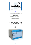
1
Title
1 CHANNEL TEMPERATURE
TRANSMITTER
TYPE SILBUS-TX1T
USER'S MANUAL
Document Number
120-359-12
Issue
02
1 OF 23
REVISION CONTROL
02
Manual Corrections
2012.08.20
CG
CG
PC
01
Original
2010.11.08
PB’
PB’
JY
Issue
Details
Date
Written
Designed
Approved
Austdac Pty Ltd
Unit 1 / 4 Packard Avenue
Castle Hill NSW 2154
Australia
PO Box 6486
Baulkham Hills Business Centre
NSW 2153
Australia
Phone: + 61 2 8851 5000
Fax: + 61 2 9899 2490
Website: www.austdac.com.au
Austdac Inc.
455 Lowries Run Rd,
Pittsburgh, PA 15237
USA
Phone: +1 888 254 9155
Fax: +1 412 635 0179
Copyright 2010-10-08
This document remains the property of Austdac Pty. Ltd. It is subject to its recall and must not be
reproduced in part or whole or its contents divulged to third parties without prior written approval
from Austdac Pty Ltd.
1 CHANNEL TEMPERATURE TRANSMITTER
TYPE SILBUS-TX1T USER'S MANUAL
2 OF 23
120-359-12
Is s u e : 0 2
TABLE OF CONTENTS
REVISION CONTROL ...................................................................................................................... 2
TABLE OF CONTENTS.................................................................................................................... 3
PHOTOGRAPHS .............................................................................................................................. 4
TABLES ............................................................................................................................................ 4
FIGURES .......................................................................................................................................... 4
1 GENERAL DESCRIPTION ............................................................................................................ 5
2 FRONT PANEL LAYOUT .............................................................................................................. 5
3 THEORY OF OPERATION............................................................................................................ 6
4 OPERATING INSTRUCTIONS...................................................................................................... 8
5 CONFIGURATION......................................................................................................................... 8
5.1 CONSOLE PORT OPERATION ............................................................................................. 9
5.2 HELP COMMAND................................................................................................................. 10
5.3 REPEAT COMMAND............................................................................................................ 10
5.4 VERSION COMMAND .......................................................................................................... 11
5.5 STACK COMMAND .............................................................................................................. 11
5.6 SILBUS MAP COMMAND..................................................................................................... 12
5.7 SILBUS STATUS COMMAND .............................................................................................. 12
5.8 SILBUS GET COMMAND ..................................................................................................... 12
5.9 TEMPERATURE INPUT ADDRESS COMMAND................................................................. 13
5.10 FASTLINK MARKER COMMAND....................................................................................... 13
5.11 ANALOGUE PROTOCOL SELECT COMMAND ................................................................ 14
5.12 TRIP POINT ADD COMMAND ........................................................................................... 15
5.13 SET POINT DELETE COMMAND ...................................................................................... 15
5.14 TRIP SET POINT HYSTERESIS COMMAND .................................................................... 16
5.15 TEMPERATURE INPUT COMMAND ................................................................................. 17
5.16 RANGE COMMAND ........................................................................................................... 17
5.17 UPLOAD CONFIGURATION COMMAND .......................................................................... 17
5.18 DOWNLOAD CONFIGURATION COMMAND.................................................................... 18
6 TERMINATIONS AND CONNECTIONS...................................................................................... 20
6.1 TEMPERATURE INPUT PORT ............................................................................................ 21
6.2 SILBUS NETWORK PORT ................................................................................................... 21
7 CERTIFICATION ......................................................................................................................... 22
8 SOFTWARE REVISION AND DISPLAY...................................................................................... 22
9 SPECIFICATIONS ....................................................................................................................... 23
1 CHANNEL TEMPERATURE TRANSMITTER
TYPE SILBUS-TX1T USER'S MANUAL
3 OF 23
120-359-12
Is s u e : 0 2
PHOTOGRAPHS
Photograph 1 SILBUS-TX1T front panel........................................................................................... 5
Photograph 2 Access to console port and programming switch ....................................................... 6
Photograph 3 Laptop connected to console port via MEAN1 interface ............................................ 9
TABLES
Table 1 SILBUS-TX1T Temperature vs. Input voltage ..................................................................... 7
Table 2 Status LED flash sequence meanings ................................................................................. 8
Table 3 SILBUS-TX1T Temperature ranges................................................................................... 17
Table 4 SILBUS-TX1T Configuration record................................................................................... 20
Table 5 Temperature input termination details ............................................................................... 21
Table 6 SILBUS network port termination details ........................................................................... 22
FIGURES
Figure 1 PT100 sensors and typical lead identifications................................................................... 7
Figure 2 Sensor input schematic ...................................................................................................... 7
Figure 3 SIBUS-TX1T Connection diagrams .................................................................................. 20
1 CHANNEL TEMPERATURE TRANSMITTER
TYPE SILBUS-TX1T USER'S MANUAL
4 OF 23
120-359-12
Is s u e : 0 2
1 GENERAL DESCRIPTION
The single channel temperature transmitter is part of a family of explosion protected DIN
rail mounting modules that transmit to and receive from an Austdac SILBUS field bus
network. The SILBUS-TX1T can transmit a single temperature value on an independent
valid SILBUS channel.
The single temperature input is designed to work with a standard two, three or four wire
PT100 temperature sensor. The temperature transmitter can be configured to operate on
one two temperature ranges, -10ºC to +100ºC or -20ºC to +200ºC. This makes the SILBUSTX1T particularly suited to monitoring bearing or similar plant temperatures via the SILBUS
network without any requirements for additional power.
The transmitter is housed within a DIN rail mounting enclosure measuring 45mm (W) x
75mm (H) x 110mm (D). The front panel is located between the two top of enclosure
mounted terminal blocks to provide a clear view of the operation indicating LED. A single
LED is provided to show SILBUS network status.
The SILBUS-TX1T can be quickly and simply configured using a laptop computer running
Hyper Terminal and a small plug in programming adaptor. The single temperature input can
be programmed to any SILBUS channel address. The temperature input can also have it’s
over range, hysteresis, digital set point alarm channels and analogue transmission protocol
configured by the user.
2 FRONT PANEL LAYOUT
The single channel temperature transmitter front panel is located between the terminal
blocks that form part of the enclosure. The front panel is shown in photograph 1 below.
Photograph 1 SILBUS-TX1T front panel
1 CHANNEL TEMPERATURE TRANSMITTER
TYPE SILBUS-TX1T USER'S MANUAL
5 OF 23
120-359-12
Is s u e : 0 2
Located in the top right hand corner of the front panel is the STATUS indication LED. The
orange status LED flashes at different rates to indicate the operational status of the
transmitter, see table 1 for more details.
The front panel can be snapped out and removed by using a wide bladed flat screw driver
to gain access to the configuration (console) port and programming switch. Photograph 2
below shows the front panel removed and the location of the console port and programming
switch.
Photograph 2 Access to console port and programming switch
The black four pin console port connector and the red programming switch are located
behind the upper left corner of the front panel label.
3 THEORY OF OPERATION
The single channel temperature transmitter takes a single input from a PT100 sensor and
transmits it onto the connected SILBUS network using either the ANALINK or FASTLINK
protocols. The temperature input is converted to a sixteen bit (Fastlink) or eight bit (Analink)
value ready for transmission on the configured SILBUS channel. The analogue
transmission protocol can be configured for the temperature input. See Austdac document
120-009-10 for a more detailed description of SILBUS communications.
The PT100 sensor is a two, three or four wire resistor that varies its resistance according to
the surrounding temperature. The sensor has a resistance of 100Ω at 0ºC. The sensor
resistance increases with temperature. The PT100 sensor will work with 2 wires but the
resistance of the sensor leads also contribute to the change in resistance and introduce
errors. Three and four wire sensors provide Kelvin connections that allow for the lead
1 CHANNEL TEMPERATURE TRANSMITTER
TYPE SILBUS-TX1T USER'S MANUAL
6 OF 23
120-359-12
Is s u e : 0 2
resistance errors to be compensated out of the final temperature reading. The SILBUSTX1T carries out three-wire lead compensation on three and four-wire sensors, two-wire
sensors will work with the transmitter but no compensation is possible. Use three or fourwire sensors for better accuracy. The figure below shows three and four wire PT100
sensors and typical lead identifications.
B
RED
B
RED
W1
B
RED
B
RED
W2
A
WHT
W3
A
WHT
A
WHT
W4
Figure 1 PT100 sensors and typical lead identifications
The SILBUS-TX1T temperature transmitter functions by driving a constant current of 200uA
out of terminal 8 through the PT100 sensor and back in through terminal 11. This current
will cause a voltage to appear across the sensor proportional to the sensor temperature.
1.2V
200uA
PT100
TEMPERATURE
SENSOR
DRIVE
8
SENSE
9
20mV @ 0 degC
100R @ 0 degC
10
GND
11
0V
Figure 2 Sensor input schematic
The sensor voltage and therefore temperature is measured at terminal 9 of the transmitter.
SILBUS-TX1T TEMPERATURE VS. INPUT VOLTAGE
TEMPERATURE ºC
SENSOR RESISTANCE Ω
INPUT VOLTAGE mV
-20
92
18.4
-10
96
19.2
0
100
20.0
+10
104
20.8
+20
108
21.6
+30
112
22.4
+40
115
23.0
+50
119
23.8
+100
138
27.6
+150
157
31.4
+200
176
35.2
Table 1 SILBUS-TX1T Temperature vs. Input voltage
The sensor voltage at terminal 9 does not include any error voltages introduced by the lead
from terminal 8 to the sensor. The sensor voltage at 0ºC is 20mV.
1 CHANNEL TEMPERATURE TRANSMITTER
TYPE SILBUS-TX1T USER'S MANUAL
7 OF 23
120-359-12
Is s u e : 0 2
The table above shows some typical temperatures, sensor resistances and SILBUS-TX1T
input voltages.
The temperature input is also monitored for under and over temperature by comparing it to
configured set points. The under or over temperature can be transmitted as a digital signal
on any valid configurable SILBUS channel address. A hysteresis level can be configured for
each input to stop the set point alarms from chattering because of noise on the temperature
signal from the sensor.
All configurable aspects of the temperature transmitter can be programmed via the console
port. The transmitter will operate with 8, 16, 32, 64 and 128 channel SILBUS networks and
will automatically configure to the number of channels of the connected SILBUS network.
4 OPERATING INSTRUCTIONS
The single channel temperature transmitter does not require any operator action to operate
once it has been installed within an IP54 host enclosure and configured correctly.
An understanding of the various flash sequences of the orange status LED may be required
to help in the trouble shooting and maintenance of the entire SILBUS network installation.
The status LED provides information on the operational status of the transmitter and the
connected SILBUS network. This information includes correct microprocessor operation
and health of connected SILBUS network. The table below shows the various flash
sequences and their meaning.
FLASH SEQUENCE
NONE – LED ON OR
OFF CONTINUOUSLY
QUICK FLASH EVERY
1.36mS
STATUS LED FLASH SEQUENCES
NAME
MEANING
NO FLASH
INTERNAL MICROPROCESSOR FAULT OR NO POWER.
TRANSMITTER FUNCTIONING – HEALTHY SILBUS
CONNECTED TO SILBUS PORT.
Table 2 Status LED flash sequence meanings
FAST FLASH
The console port power source selection switch SW1 must always be in the run position for
correct operation of the transmitter. The run position is with the small slide actuator pushed
closest to the black four pin console connector X1.
5 CONFIGURATION
The single channel temperature transmitter has several operational parameters that require
configuration prior to use. All of these parameters can be viewed and changed via the
console port. The console port consists of a small four pin connector and a two position
slide switch behind the front panel label. Access to the console port can be gained by
snapping out the front panel using a wide bladed flat screw driver in one of the slots
between the front panel and terminal blocks.
To use the console port an Austdac MEAN1 interface, A to B USB cable and laptop
computer running Hyper Terminal are required.
For more detail on the console port, MEAN1 interface and their use refer to Austdac
document 53-018-11.
1 CHANNEL TEMPERATURE TRANSMITTER
TYPE SILBUS-TX1T USER'S MANUAL
8 OF 23
120-359-12
Is s u e : 0 2
5.1 CONSOLE PORT OPERATION
The console port should be connected to a laptop running a terminal emulation program
such as Hyper Terminal via the Austdac interface type MEAN1 and a USB cable as
shown in the following photograph.
Photograph 3 Laptop connected to console port via MEAN1 interface
The SILBUS-TX1T certification places restrictions on what may be connected to the
console port, the connection of an interface other than the Austdac MEAN1 to the console
port will invalidate the certification of the transmitter.
The terminal emulation program should be configured to 19200 baud, 8 data bits, one
stop bit, no parity, no flow control and DEC VT100 terminal emulation.
Once communications have been established with the SILBUS-TX1T, it will display a
screen of information that includes software version, software checksum, and a list of
commands followed by the console port prompt.
The prompt includes an abbreviation of the transmitter type number. TX1T::> Commands are invoked by entering the command name followed by any optional
modifiers, keywords and the “ENTER” key. The enter key is shown in the following
examples as a “ ” symbol.
1 CHANNEL TEMPERATURE TRANSMITTER
TYPE SILBUS-TX1T USER'S MANUAL
9 OF 23
120-359-12
Is s u e : 0 2
5.2 HELP COMMAND
The HELP command prints a list of all available commands and shows the syntax for each
command. Optional command modifiers are shown within [ ] while mandatory modifiers
are shown within < >. An example of a screen output follows:
TX1T::>HELP Software 1V01 0xBA57 Configuration 0xFFF6 SN:10031234 Commands: ‐‐‐‐‐‐‐‐‐‐‐‐‐‐‐‐‐‐‐‐‐‐‐‐‐‐‐‐‐‐‐‐‐‐‐‐‐‐‐‐‐‐‐‐‐‐‐‐‐‐‐‐‐‐‐‐‐‐‐‐‐‐‐‐‐‐‐‐‐‐‐‐‐‐‐‐‐‐
********** Level 1: Standard Menu ********** HELP [1…7] Level of Help Displays Help Menu REPEAT [LF] [Refresh rate in seconds] Repeats Previous Command VER Displays Firmware Version and Checksum STACK Displays Peak Stack Usage SBMAP Displays SILBUS I/O Map SBSTAT Displays SILBUS Status SBGET <A1–P8> Display selected SILBUS Channel State SBADDR [<SET> <FREQ I/P> <A1‐P8 or DISABLE>] Set Temperature SILBUS Address FSTMRK [<SET> <A1‐P8 or DISABLE>] Set Fastlink Marker Address ANASEL [<SET> <ANA I/P> <ANALINK|FASTLINK>] Set Analogue Protocol ADDPT [<SET> <A1‐P8> <FALL|RISE> <Hz>] Add Temperature Trip Points DELPT [<SET> <Trip Point Number|ALL>] Delete Temperature Trip Points TRPHYS [<SET> <degC>] Set Trip Point Hysteresis Range degC RANGE [<SET> <Normal | Wide>] Normal ‐10 to 100, Wide ‐20 to 200 TEMP Display Temperature in degC CFGUP Upload Configuration Text CFGDWN Download Configuration Text ‐‐‐‐‐‐‐‐‐‐‐‐‐‐‐‐‐‐‐‐‐‐‐‐‐‐‐‐‐‐‐‐‐‐‐‐‐‐‐‐‐‐‐‐‐‐‐‐‐‐‐‐‐‐‐‐‐‐‐‐‐‐‐‐‐‐‐‐‐‐‐‐‐‐‐‐‐‐‐‐ TX1T::>_ 5.3 REPEAT COMMAND
The REPEAT command is used after another command to continuously repeat that
command. As an example the SBGET command can be executed followed by the
REPEAT command to provide a continuously updating display of the selected SILBUS
channel. The display will continue to update until any key is hit. The TX1T will respond by
displaying the prompt.
TX1T::>SBGET D1 D1 = ON TX1T::>REPEAT D1 = OFF TX1T::>_ In the above example the “OFF” changed to an “ON” whenever SILBUS channel D1 was
activated. In this mode the repeat command writes over the previously displayed
information, if required, the repeat command can be made to refresh the information on a
new line by entering LF (line feed) as part of the command invocation. The repeat
command refreshes the display every one second by default. The refresh rate can be
1 CHANNEL TEMPERATURE TRANSMITTER
TYPE SILBUS-TX1T USER'S MANUAL
10 OF 23
120-359-12
Is s u e : 0 2
slowed by entering the refresh rate in seconds as part of the repeat command as shown in
the following command:
TX1T::>REPEAT LF 5 D1 = OFF D1 = OFF D1 = ON D1 = OFF D1 = OFF D1 = ON D1 = OFF TX1T::>_ As can be seen from the above example the repeat command refreshed the status of
SILBUS channel D1 on a new line every five seconds. In the LF mode a record of the
status of D1 can be viewed on the screen.
5.4 VERSION COMMAND
The VERSION command is used to display the serial number, abbreviated type number,
software version, program memory checksum and configuration checksum of the TX1T.
The command can be invoked as shown in the following example:
TX1T::>VER TX1T Software 1V02 0xBA57 Configuration 0xFFF6 SN:09124321 TX1T::>_ This command is useful when the user needs to know the software version or serial
number. The program memory checksum is useful to confirm that a software update has
completed successfully without any programming errors.
5.5 STACK COMMAND
The STACK command is provided to allow the technician to gauge the health of the TX1T
microprocessor and its code by displaying the maximum usage of the program stack. The
display is a peak value of the stack usage since the TX1T was powered up. The
command can be invoked as shown in the example below:
TX1T::>STACK Stack usage/size = 312/1024 Percentage Used = 30% TX1T::>_ This command would typically only be used when requested by an Austdac software
engineer.
1 CHANNEL TEMPERATURE TRANSMITTER
TYPE SILBUS-TX1T USER'S MANUAL
11 OF 23
120-359-12
Is s u e : 0 2
5.6 SILBUS MAP COMMAND
The SILBUS map command allows the operator to obtain a snapshot of the SILBUS
network to which the transmitter is connected. The map shows all of the SILBUS channels
available on the network. The map consists of a table with a heading of groups below
which is displayed the channels using ones and zeros. Each group is shown vertically with
1 at the top and 8 at the bottom. A one indicates an ON channel and a zero indicates an
OFF channel. An example of an SBMAP is shown below with channels A4, P7 and P8 on
or active:
TX1T::>SBMAP ABCDEFGHIJKLMNOP 0000000000000000 0000000000000000 0000000000000000 1000000000000000 0000000000000000 0000000000000000 0000000000000001 0000000000000001 TX1T::>_ The SBMAP command is particularly useful when used with the repeat command as this
will display a continuously updated table.
5.7 SILBUS STATUS COMMAND
The SILBUS status command displays the number of SILBUS channels available on the
connected SILBUS network, a SILBUS synchronisation pulse count and a SILBUS error
count. This command is used to determine if the connected SILBUS network is functioning
correctly and how many channels are available. The error count should typically be zero
while the sync count should be incrementing. Once again the use of the repeat command
will provide a dynamic updating display. An example of the SBSTAT command follows:
TX1T::>SBSTAT No. Chan = 128, Sync Count = 17807, Error Count = 0 TX1T::>_ The error count will be non zero whenever the connected SILBUS network is out of
specification. The error count can be non zero if the connected SILBUS network channel
generator has its power supply cycled off and on. These error counts should be ignored.
5.8 SILBUS GET COMMAND
The SILBUS get command is used to display the status of one selected SILBUS channel
only. If this command is used in conjunction with the repeat command a continuously
updating display can be achieved. The command is invoked by entering the command
name followed by the desired channel address as shown in the two examples below:
1 CHANNEL TEMPERATURE TRANSMITTER
TYPE SILBUS-TX1T USER'S MANUAL
12 OF 23
120-359-12
Is s u e : 0 2
TX1T::>SBGET M3 M3 = OFF TX1T::>SBGET B7 B7 = ON TX1T::>_ 5.9 TEMPERATURE INPUT ADDRESS COMMAND
This command is used to display and configure the SILBUS channel address of the
temperature input of the SILBUS-TX1T. The current SILBUS channel can be displayed by
simply entering the command name as shown in the example below:
TX1T::>SBADDR Temperature Address = A6 TX1T::>_ If the command name is entered with additional attributes the channel address can be
configured to any valid SILBUS address. There is no restriction on the SILBUS address..
An example of configuring input 2 is shown below:
TX1T::>SBADDR SET K7 Setting Changed Temperature Address = K7 TX1T::>_ The above example shows the format of the command when the temperature address is
configured. The keyword “SET” is required to invoke a change; followed by the SILBUS
channel address for the temperature. The keyword “DISABLE” is used when a SILBUS
channel is not required for the temperature signal, but the end user may still wish to use
the trip alarm signals (see section 5.12).
.
TX1T::>SBADDR SET DISABLE Setting Changed Temperature Address = ‐‐ TX1T::>_ 5.10 FASTLINK MARKER COMMAND
This command is used to display and configure the FASTLINK marker SILBUS channel
address. A valid FASTLINK marker is required whenever the temperature input is
configured to transmit using the FASTLINK protocol. The marker is generated by the
GSW1 channel generator and can be any valid SILBUS channel address. Only one
marker is required per SILBUS field bus network. The current marker channel address
can be displayed by simply entering the command name as shown in the example below:
1 CHANNEL TEMPERATURE TRANSMITTER
TYPE SILBUS-TX1T USER'S MANUAL
13 OF 23
120-359-12
Is s u e : 0 2
TX1T::>FSTMRK Fastlink Marker is A3 TX1T::>_ The example below shows the format of the command when the marker address is
configured. The keyword “SET” is required to invoke a change, followed by the SILBUS
channel address of the FASTLINK marker. If FASTLINK is not to be used by the TX1T
transmitter then the marker channel should be disabled. The keyword “DISABLE” is used
when the marker channel is not required.
TX1T::>FSTMRK SET DISABLE Setting Changed Fastlink Marker is DISABLE TX1T::>_ 5.11 ANALOGUE PROTOCOL SELECT COMMAND
This command is used to display and configure the analogue transmission protocol for the
temperature input. The temperature input can be configured to either Analink or Fastlink
transmission protocol. The current selected transmission protocol can be displayed by
simply entering the command name as shown in the example below:
TX1T::>ANASEL Temperature SILBUS Analog Protocol = Analink TX1T::>_ If the command name is entered with additional attributes the analogue transmission
protocol can be configured to Fastlink or Analink for the temperature input. An example of
configuring the protocol is shown below:
TX1T::>ANASEL SET FASTLINK Setting Changed Temperature SILBUS Analog Protocol = Fastlink (Marker Error) TX1T::>_ The ‘marker error’ has been displayed because the temperature input has been
configured to Fastlink but a valid Fastlink marker channel address has not been specified.
See the Fastlink marker command (FSTMRK) for details on assigning a valid marker
address. Refer to Austdac document 120-009-10 for more detail on the various analogue
and data transmission protocols. Once a valid marker address has been configured the
error message will disappear as shown in the example below.
TX1T::>ANASEL Temperature SILBUS Analog Protocol = Fastlink TX1T::>_ 1 CHANNEL TEMPERATURE TRANSMITTER
TYPE SILBUS-TX1T USER'S MANUAL
14 OF 23
120-359-12
Is s u e : 0 2
5.12 TRIP POINT ADD COMMAND
This command is used to display and configure the SILBUS channel addresses, direction
and level of the trip point alarms of the SILBUS-TX1T. The trip alarms are generated
when the temperature input passes a preconfigured rising or falling trip point level. Up to
five trip point alarms can be assigned to the temperature input. The current configuration
of the set points can be displayed by simply entering the command name as shown in the
example below:
TX1T::>ADDPT No Limit Points TX1T::>_ The above example shows that no set points have been configured. If the command is
entered with additional attributes more set points can be added to the configuration up to
the upper limit of five set points. There is no restriction on the SILBUS addresses; they do
not have to be in numerical order or from the same group. An example of adding a new
set point is shown below:
TX1T::>ADDPT SET J2 RISE 85 Setting Changed 1: J2 Trips on a rising edge at 85.0degC TX1T::>_ The above example shows the adding of a set point to the temperature input. The
keyword “SET” is required to invoke an addition; the address of the SILBUS digital
channel is next, followed by the keyword “RISE” and the value of the set point level in
degrees C.
TX1T::>ADDPT SET J3 FALL 65.1 Setting Changed 1: J2 Trips on a rising edge at 85.0degC 2: J3 Trips on a falling edge at 65.1degC TX1T::>_ The above example shows the adding of a second set point to the temperature input. The
keyword “SET” is required to invoke an addition; the address of the SILBUS digital
channel is next, followed by the keyword “FALL” and the value of the set point level in
degrees C.
5.13 SET POINT DELETE COMMAND
This command is used to display or delete set points from the temperature input. The
current configuration of the set points can be displayed by simply entering the command
name as shown in the example below:
TX1T::>DELPT 1: J2 Trips on a rising edge at 85.0degC 2: J3 Trips on a falling edge at 65.1degC 1 CHANNEL TEMPERATURE TRANSMITTER
TYPE SILBUS-TX1T USER'S MANUAL
15 OF 23
120-359-12
Is s u e : 0 2
TX1T::>_ The use of the set point delete command without any attributes does not delete any set
points.
TX1T::>DELPT SET 1 Setting Changed 1: J3 Trips on a falling edge at 65.1degC TX1T::>_ The above example shows the deletion of the first set point. The keyword “SET” is
required to invoke the deletion. The number “1” specifies which set point to delete. Note
that remaining set points are renumbered after execution of the delete command. The
next example shows the use of the keyword “ALL” with the delete set point command.
TX1T::>DELPT SET ALL All points deleted TX1T::>_ 5.14 TRIP SET POINT HYSTERESIS COMMAND
This command is used to display and configure the common set point hysteresis for the
temperature input. The hysteresis value is used to stop the set point alarms from
switching on and off with any noise that may be present on the temperature input signal.
For example if the temperature input was currently at 64.9ºC and the set point level was
set at 65ºC for a rising alarm, the input signal would only need slightly more than 0.01ºC
of noise or jitter to cause the set point alarm to randomly switch on and off. By setting the
hysteresis value to slightly higher than any known noise this random and annoying
switching can be eliminated. The hysteresis value is common to all setpoints. The current
hysteresis value can be displayed by simply entering the command name as shown in the
example below:
TX1T::>TRPHYS Hysteresis level 0.5degC TX1T::>_ If the command name is entered with additional attributes the hysteresis level can be
configured to any valid level. An example of configuring the hysteresis level is shown
below:
TX1T::>TRPHYS SET 0.3 Setting Changed Hysteresis level 0.3degC TX1T::>_ The range of the hysteresis is from 0.1ºC to 10ºC.
1 CHANNEL TEMPERATURE TRANSMITTER
TYPE SILBUS-TX1T USER'S MANUAL
16 OF 23
120-359-12
Is s u e : 0 2
5.15 TEMPERATURE INPUT COMMAND
The temperature input command is used to display the current value of the temperature
input. The example below shows the temperature being displayed:
TX1T::>TEMP Temperature = 110.4degC TX1T::>_ 5.16 RANGE COMMAND
The range command is used to select the measurement range of the SILBUS-TX1T
temperature transmitter. The example below shows the temperature being displayed:
TX1T::>RANGE Temperature range is normal TX1T::>_ The SILBUS-TX1T has two temperature measurement ranges labelled normal and wide.
These ranges are shown in the following table.
SILBUS-TX1T TEMPERATURE MEASUREMENT RANGES
NAME
TEMPERATURE RANGE
NORMAL
-10ºC to +100ºC
WIDE
-20ºC to +200ºC
Table 3 SILBUS-TX1T Temperature ranges
The example below shows how the range command can be used to configure the
temperature measurement range:
TX1T::>RANGE SET WIDE Setting Changed Temperature range is wide TX1T::>_ 5.17 UPLOAD CONFIGURATION COMMAND
The upload configuration command is used to extract the configuration profile of the
SILBUS-TX1T via the MEAN1 interface and record it in a file on a PC. Having an exact
copy of the configuration is useful for record keeping and future cloning of new SILBUSTX1T transmitters for maintenance or system expansion. The upload is invoked by
entering the command name without any attributes as shown in the example below.
TX1T::>CFGUP CFGDWN S00300000FC S11300000000001001022E008056000105000000CF S113001080000000800000008000000080000000DC S11300208000140008001E00090028000A000000D7 1 CHANNEL TEMPERATURE TRANSMITTER
TYPE SILBUS-TX1T USER'S MANUAL
17 OF 23
120-359-12
Is s u e : 0 2
S113003080000000800000006492000011002ED9AE S9030000FC TX1T::>_ The configuration is uploaded and displayed on the screen in Motorola S1-S9® HEX
format. This data format includes headers and checksums to guard against errors and
corruption of the data. The first line of the uploaded configuration is the keyword
“CFGDWN” this does not form part of the data but is included to help with the
configuration download process, see section 5.17 below for details.
To save the configuration to a file, open Notepad or a similar non-word processing editor,
highlight the uploaded configuration as indicated below and copy to Notepad via the
clipboard. The Notepad file should then be saved with a meaningful title that reflects the
application e.g. TX1T_xxx.CFG. When highlighting the uploaded configuration, ensure
that the invisible carriage returns (CR) at the end of all lines are included. Also ensure that
the CFGDWN keyword is included.
TX1T::>CFGUP CFGDWN S00300000FC S11300000000001001022E008056000105000000CF S113001080000000800000008000000080000000DC S11300208000140008001E00090028000A000000D7 S113003080000000800000006492000011002ED9AE S9030000FC TX1T::>_ The copy and paste method is used in this manual because it is the most universal
method that works with all terminal emulation programs such as HyperTerminal®. Do not
use an editor that introduces hidden formatting characters as a future download may not
work with these characters in place. Many terminal emulation programs have automatic
means to upload the configuration directly into a file; these are not described here as they
differ from program to program but there is no restriction on using these features. Austdac
is planning to release a complete tool to allow direct upload, download and editing of the
configuration profile.
5.18 DOWNLOAD CONFIGURATION COMMAND
The download configuration command is used to take a previously saved configuration
from a file and download it to the target SILBUS-TX1T transmitter. This method of
configuration ensures exact cloning during maintenance and system expansions.
Communications with the target must first be established via the MEAN1 interface and a
terminal emulation program such as Hyper Terminal®. The cursor should be left at the
SILBUS-TX1T prompt as follows.
TX1T::>_ 1 CHANNEL TEMPERATURE TRANSMITTER
TYPE SILBUS-TX1T USER'S MANUAL
18 OF 23
120-359-12
Is s u e : 0 2
Open the previously saved configuration file in Notepad or a similar non-word processing
editor and highlight the configuration as shown below.
CFGDWN S00300000FC S11300000000001001022E008056000105000000CF S113001080000000800000008000000080000000DC S11300208000140008001E00090028000A000000D7 S113003080000000800000006492000011002ED9AE S9030000FC Copy and paste the configuration from Notepad to the TX1T::> prompt in Hyper Terminal
as shown below. Note CTRL-V does not work in Hyper Terminal.
TX1T::>CFGDWN S00300000FC S11300000000001001022E008056000105000000CF S113001080000000800000008000000080000000DC S11300208000140008001E00090028000A000000D7 S113003080000000800000006492000011002ED9AE S9030000FC TX1T::>_ The first line of the configuration contains the keyword “CFGDWN” which instructs the
target to accept the data records. This “CFGDWN” keyword should have been copied
from a previous upload and saved in the configuration file. Automatic file transmission
features of the terminal emulation program may be used to download configuration files.
Photograph 4 Hyper Terminal delay setup
1 CHANNEL TEMPERATURE TRANSMITTER
TYPE SILBUS-TX1T USER'S MANUAL
19 OF 23
120-359-12
Is s u e : 0 2
The terminal emulation program should be set up to allow a 100mS wait period after the
carriage return at the end of each line during a download, this gives the target time to
process the incoming data.
The following table may be used to record the configuration of the SILBUS-TX1T single
channel temperature transmitter.
SILBUS-TX1T CONFIGURATION RECORD
LOCATION
SILBUS NETWORK
TEMPERATURE INPUT ADDRESS
MEASUREMENT RANGE
TRANSMISSION PROTOCOL
SET POINT 1 RISE/FALL AND LEVEL
SET POINT 2 RISE/FALL AND LEVEL
SET POINT 3 RISE/FALL AND LEVEL
SET POINT 4 RISE/FALL AND LEVEL
SET POINT 5 RISE/FALL AND LEVEL
SET POINT HYSTERESIS
FASTLINK MARKER ADDRESS
CONFIGURATION CHECKSUM
Table 4 SILBUS-TX1T Configuration record
6 TERMINATIONS AND CONNECTIONS
SIG 1
8 DRIVE
9 +SENSE
3 OR 4 WIRE
PT100 SENSOR
4 WIRE ONLY
SILBUS NETWORK
All connections to the single channel temperature transmitter are via cage-clamp terminals
around the perimeter and near the front of the DIN rail mounting enclosure, these terminals
can accommodate up to 4mm2 conductors. There are seven possible connections to the
transmitter; these are shown in the following tables and diagrams:
CH 1
10-SENSE
COM 2
12 EMC
1 CH TEMPERATURE TX
TYPE SILBUS-TX1T
SIGNAL
COMMON
11 GND
2 WIRE
PT100 SENSOR
NC
8 DRIVE
SIG
9 +SENSE
COM 2
10 -SENSE
CH 1
SILBUS NETWORK
EARTH
1
1 CH TEMPERATURE TX
TYPE SILBUS-TX1T
SIGNAL
COMMON
11 GND
12 EMC
EARTH
Figure 3 SIBUS-TX1T Connection diagrams
1 CHANNEL TEMPERATURE TRANSMITTER
TYPE SILBUS-TX1T USER'S MANUAL
20 OF 23
120-359-12
Is s u e : 0 2
6.1 TEMPERATURE INPUT PORT
The temperature input is provided with four terminals for the connection of the PT100
sensor. The SILBUS-TX1T temperature input will accept two, three or four wire PT100
sensors, the figures above show the connection of the sensor to the temperature
transmitter. Terminal 12 is provided for connecting of earth to shunt away transients and
noise. Use minimum 2.5mm2 conductor for this connection.
INPUT
CH1
TERM #
8
9
10
11
12
TEMPERATURE INPUT TERMINATIONS
LABEL
DESCRIPTION
DRIVE
200uA CURRENT DRIVE OUTPUT
+SENSE +VE SENSE INPUT
-SENSE -VE SENSE INPUT (Not implemented on SILBUS-TX1T)
GND
GROUND RETURN
EMC
EMC EARTH CONNECTION
Table 5 Temperature input termination details
The +SENSE terminal 9 is linked to the DRIVE terminal 8 for two wire PT100 sensors only.
The –SENSE input is not implemented on the SILBUS-TX1T. Terminal 10 is only there to
provide a place to terminate the –SENSE wire of a four wire sensor, no additional
compensation is provided beyond that of a three wire sensor.
The temperature input is not galvanically isolated from the SILBUS network port; therefore
it is important that the sensor and its wiring are completely isolated from earth or ground to
avoid placing earths on the SILBUS network. The common mode noise rejection
capabilities of the SILBUS network are significantly compromised if the SILBUS network is
connected to earth or ground.
Photograph 5 Typical 3 wire PT100 sensor
6.2 SILBUS NETWORK PORT
The SILBUS network port provides a means for the transmitter to be connected to a
SILBUS network. Any connections to a SILBUS field bus network pair should be of a multidrop nature with spur lengths kept to a minimum. This will minimize any reflections and
therefore communications errors in the SILBUS network.
1 CHANNEL TEMPERATURE TRANSMITTER
TYPE SILBUS-TX1T USER'S MANUAL
21 OF 23
120-359-12
Is s u e : 0 2
TERMINAL
1
2
SILBUS NETWORK PORT TERMINATIONS
DESIGNATION
DESCRIPTION
SIG
SILBUS NETWORK SIGNAL
COM
SILBUS NETWORK COMMON
Table 6 SILBUS network port termination details
The table above shows the SILBUS network port connections.
7 CERTIFICATION
The single channel temperature transmitter type SILBUS-TX1T has been awarded IECEx
certification under IECEx TSA 07.0002X, Ex ia I, as part of the Dupline / SILBUS system.
The certification requires that the SILBUS-TX1T be mounted within a host enclosure that
provides a minimum ingress protection of IP54 (IP55 for Queensland Australia).
The certificate should be consulted for any special conditions of use when designing the
SILBUS-TX1T into an installation.
8 SOFTWARE REVISION AND DISPLAY
The software version of the four channel analogue transmitter type SILBUS-TX1T will vary
as its functionality is improved at the request of our customers. The software version is
given in two parts, the major revision level and the minor revision level and is written in the
following format:
VERSION M.mm where M represents the major revision level and mm represents the minor
revision level. E.g. VER 1.12
The software version can be determined by using the VER command on both console
ports. Both ports should give the same firmware version. Refer to the SILBUS-SNM1
software release register (120-366-01) for a history of software / firmware updates.
1 CHANNEL TEMPERATURE TRANSMITTER
TYPE SILBUS-TX1T USER'S MANUAL
22 OF 23
120-359-12
Is s u e : 0 2
9 SPECIFICATIONS
Name ........................................................................ Single Channel Temperature Transmitter
Type .....................................................................................................................SILBUS-TX1T
Number of temperature channels ............................................................................................ 1
Sensor type................................................................................ PT100 (2 wire, 3wire or 4wire)
Temperature range ........................................................... -10ºC to +100ºC or -20ºC to +200ºC
Sensor drive current......................................................................................................... 200uA
Temperature input transmission protocol..............................................FASTLINK or ANALINK
Resolution ANALINK............................................. Normal (0.43oC/LSB) or Wide (0.86oC/LSB)
Resolution FASTLINK........................................... Normal (0.03oC/LSB) or Wide (0.05oC/LSB)
Inaccuracy...................................................................................≤ 0.5oC Normal, ≤ 1.0oC Wide
Temperature Drift.................................................... ≤ 0.03oC (relative to ambient temperature)
Console port configuration .............................................. 19200 baud, 8 data, 1 stop, No parity
Terminations ................................................................................ Cage clamp 4mm2 maximum
Size .................................................................................. 45mm (W) x 75mm (H) x 110mm (D)
Mass .................................................................................................................................. 135g
Fixing ............................................................................................................ TS35 DIN rail only
Ingress protection ............................................................................................................... IP20
Enclosure material ............................................................. Polycarbonate (30%GV) UL 94 V-1
Enclosure colour ................................................................................................RAL 7032 Grey
Terminal material ............................................................................... Polycarbonate UL 94 V-2
Terminal block colour.......................................................................................................... Blue
Operating temperature range.................................................................................. 0ºC to 40ºC
Storage temperature range.................................................................................. -20ºC to 80ºC
Operating relative humidity range ................................................ 10% to 90% Non condensing
Power supply operating voltage range........................................SILBUS network line powered
1 CHANNEL TEMPERATURE TRANSMITTER
TYPE SILBUS-TX1T USER'S MANUAL
23 OF 23
120-359-12
Is s u e : 0 2