1
Process Control Valves
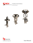
Model 9100
RCV-UM-00588-EN-02 (August 2015)
User Manual
Process Control Valves, Model 9100
CONTENTS
Scope of This Manual . . . . . . . . . . . . . . . . . . . . . . . . . . . . . . . . . . . . . . . . . . . . . . . . . . . . . . . . . . . . . . . . . . . . 3
Unpacking and Inspection . . . . . . . . . . . . . . . . . . . . . . . . . . . . . . . . . . . . . . . . . . . . . . . . . . . . . . . . . . . . . . . . 3
Safety . . . . . . . . . . . . . . . . . . . . . . . . . . . . . . . . . . . . . . . . . . . . . . . . . . . . . . . . . . . . . . . . . . . . . . . . . . . . . 3
Description . . . . . . . . . . . . . . . . . . . . . . . . . . . . . . . . . . . . . . . . . . . . . . . . . . . . . . . . . . . . . . . . . . . . . . . . . . 4
Installation . . . . . . . . . . . . . . . . . . . . . . . . . . . . . . . . . . . . . . . . . . . . . . . . . . . . . . . . . . . . . . . . . . . . . . . . . . 5
Re-Orienting the Actuator . . . . . . . . . . . . . . . . . . . . . . . . . . . . . . . . . . . . . . . . . . . . . . . . . . . . . . . . . . . . . . 5
Installation Considerations . . . . . . . . . . . . . . . . . . . . . . . . . . . . . . . . . . . . . . . . . . . . . . . . . . . . . . . . . . . . . 5
Operation . . . . . . . . . . . . . . . . . . . . . . . . . . . . . . . . . . . . . . . . . . . . . . . . . . . . . . . . . . . . . . . . . . . . . . . . . . 6
Adjusting Actuator Spring Loading . . . . . . . . . . . . . . . . . . . . . . . . . . . . . . . . . . . . . . . . . . . . . . . . . . . . . . . . . . 7
Schematic of ATO Valve with Standard Moore 750 Positioner and Airset (Piped) . . . . . . . . . . . . . . . . . . . . . . . . . . . . . . 8
Removing the Actuator from the Valve Subassembly . . . . . . . . . . . . . . . . . . . . . . . . . . . . . . . . . . . . . . . . . . . . 8
Disassembling the Valve Subassembly . . . . . . . . . . . . . . . . . . . . . . . . . . . . . . . . . . . . . . . . . . . . . . . . . . . . . . 9
Re-Assembling the Valve Subassembly . . . . . . . . . . . . . . . . . . . . . . . . . . . . . . . . . . . . . . . . . . . . . . . . . . . . . 9
Engineering Drawings . . . . . . . . . . . . . . . . . . . . . . . . . . . . . . . . . . . . . . . . . . . . . . . . . . . . . . . . . . . . . . . . . . 11
Page ii
RCV-UM-00588-EN-02
August 2015
Scope of This Manual
SCOPE OF THIS MANUAL
This manual explains how to install and operate the Model 9100 Control valve.
Read this manual carefully before attempting any installation or operation. Keep the manual accessible for future reference.
UNPACKING AND INSPECTION
Upon opening the shipping container, visually inspect the product and applicable accessories for any physical damage such
as scratches, loose or broken parts, or any other sign of damage that may have occurred during shipment.
NNOTE: If damage is found, request an inspection by the carrier’s agent within 48 hours of delivery and file a claim with the
carrier. A claim for equipment damage in transit is the sole responsibility of the purchaser.
SAFETY
The installation of the valve must comply with all applicable federal, state, and local rules, regulations, and codes.
• Follow your company's safety rules concerning equipment installation or repairs.
• Read the user manual and brochure before attempting repairs.
• Never use this or any valve in an application that is above the limits of the unit.
• Never use the valve above the pressure/temperature rating listed in the brochure.
• Never use the valve in applications that attack bronze materials.
• De-pressurize the system before disassembling the valve.
• Never rotate the innervalve when in the closed position.
• Rotation of metal on metal components causes galling and will affect the function and shutoff capability of the unit.
ON ACTUATORS WITH TWO (2) LONG ACTUATOR BOLTS, THE SPRINGS ARE UNDER TENSION EVEN WHEN ACTUATOR IS
OFF THE VALVE.
WHEN DISASSEMBLING ACTUATOR, REMOVE LONG NUTS LAST TO RELIEVE SPRING COMPRESSION.
DO NOT ROTATE THE ACTUATOR STEM. USE A BACKUP WRENCH TO KEEP STEM FIXED DURING CONNECTION OF THE
INNERVALVE TO THE STEM. ROTATION OF THE STEM WILL CAUSE THE SPRINGS TO SHIFT, WHICH WILL CAUSE THE
ACTUATOR TO MALFUNCTION.
• Never use the actuator as a lever to tighten the valve body onto a pipe or fitting.
• Never clamp the body in a vice on the sides of the body. Always clamp end-to-end.
• Replace any damaged components. It’s less expensive than a shut-down.
• Remove the actuator before disassembling the valve sub-assembly.
August 2015
RCV-UM-00588-EN-02
Page 3
Description
EVEN THOUGH THE MODEL 9100 IS A RUGGED VALVE, IF THE UNIT WILL BE INSTALLED IN A HIGH VIBRATION
SITUATION, THE ACTUATOR SHOULD BE BRACED. AN ANGLE BRACKET KIT [FITTING THE ACTUATOR RIM SCREWS] IS
AVAILABLE FOR THIS PURPOSE. THE BRACKET CAN ALSO BE USED TO MOUNT ACCESSORIES TO THE ACTUATOR.
DESCRIPTION
Figure 1: Part identification
Page 4
RCV-UM-00588-EN-02
August 2015
Installation
INSTALLATION
1. Remove protective plugs from body and air signal connection.
NNOTE: Leave vent in place.
2. Install valve in pipeline using PTFE tape or other suitable pipe thread sealant.
USE HEX ON BODY TO TIGHTEN PIPE INTO BODY. NEVER USE THE ACTUATOR AS A LEVER.
3. Install a suitable 1/4" NPT fitting in the air signal connection using TFE tape or other sealant.
Re-Orienting the Actuator
IF THE AIR CONNECTIONS IN THE ACTUATOR NEED TO BE RE-ORIENTED, DO NOT SIMPLY TURN THE ACTUATOR. IF THE
UNIT IS AIR-TO-OPEN (ATO) THE FORCE ON THE INNERVALVE FROM THE CLOSURE SPRINGS WILL DAMAGE
THE INNERVALVE.
If you must re-orient the actuator:
1. Apply an air signal to the actuator to raise the innervalve off the seat (approximately mid travel).
2. Loosen the yoke locknut.
3. Re-orient the actuator.
4. Tighten the yoke locknut and THEN release the air signal pressure. To accomplish this, there is no reason to loosen either
the bonnet joint or the connection between the innervalve stem and actuator stem.
If the unit comes equipped with a positioner or other devices, refer to the instructions accompanying the accessory.
Installation Considerations
• Although the actuator can handle higher pressures, Do Not exceed the signal range stamped on the nameplate. If a
positioner is used, there is normally no need to use more than 40 psi of supply air unless the unit will not achieve full
travel.
• Do not use TFE tape to pipe positioners. Small shreds of Teflon® can cause malfunction of the positioner.
• Do not repeatedly remove air from the actuator when an ATO valve is open. Slamming the innervalve shut when dry can
cause galling of the innervalve.
August 2015
RCV-UM-00588-EN-02
Page 5
Operation
OPERATION
The Model 9100 is a modulating control valve. It is normally supplied with a 35 sq. in. pneumatic multi-spring opposed
diaphragm actuator in either Air-To-Open (ATO) or Air-To-Close (ATC) action.
The actuator spring loading of your valve has been pre-adjusted. If your size 35 actuator is an Air-To-Open version and the
signal range stamped on the nameplate is 3-15, the unit is equipped with 3 force springs and should achieve full travel
with approximately 12 psi of signal change. Since the “bench setting” is done with no upstream pressure, a 3-15 range unit
is normally set to open at 3.25…3.5 psi. This provides a minimum of “closing” force to shut off the innervalve under minimal
upstream pressures, depending on innervalve size and upstream pressure. If your valve does not close against the upstream
pressure, the springs can be adjusted (to shut off up to the maximum levels indicated in the general brochure.)
If your valve has 6 force springs and no positioner, it will be stamped 3-27 or 6-30, indicating a 24 psi span. If your valve is an
Air-To-Close version, it will be set so the innervalve touches the seat at approximately 14.5 psi.
Several factors determine a valves ability to close off with an acceptable degree of tightness. Three significant factors are:
• Upstream pressure
• Orifice diameter
• Actuator spring loading, in the case of an Air-To-Open valve. In the case of an Air-To-Close valve, maximum output air
pressure working against the innervalve and springs, determine shutoff tightness.
If the upstream pressure (P1) is multiplied by the innervalve orifice area, the upward force, in “pounds of linear force” acting
on the valve stem is determined. If that is divided by the effective area of the actuator, the minimum bench setting is known.
Normally 1/4 to 1 psi extra is required to achieve shutoff, depending on orifice diameter, seat tightness desired and the seat/
innervalve material.
For example:
P1 = 100 psi
Orifice area= 0.7854
Actuator area= 35 in. 2
Calculation: 100 x 0.7854 = 78.54 lb of upward force ÷ 35 in. 2 = 2.25 psi air.
This means that the spring loading needs to be adjusted so that if a 3…15 psi signal is nominal, we add 2.75 (1/2 psi
extra) to the minimum signal pressure (3), we know that when the controller output is 3 psi, we have the 2.75 psi
extra loading to close the valve. Without upstream pressure, the valve would require 3+2.75 = 5.75 psi of air to lift the
innervalve off the seat. With 100 psi of upstream pressure, the valve should lift off the seat at approximately. 3 psi.
If you need assistance in performing this calculation, feel free to contact Technical Support for assistance.
Page 6
RCV-UM-00588-EN-02
August 2015
Adjusting Actuator Spring Loading
ADJUSTING ACTUATOR SPRING LOADING
(Not applicable for spring ranges 6…15, 9…15 and 10…15 psi.)
In the Air-To-Open configuration, the seating force of the actuator springs can be adjusted to provide sufficient load to shut
off the innervalve. If the unit is not closing completely when the minimum signal is sent to the actuator, the spring force
needs to be increased, based on the calculation above (best done on workbench).
To increase the seating force:
1. Pipe a manual air regulator (with output gauge) to the air connection in the lower actuator housing. The regulator should
be capable of controlling pressure over the range indicated on the nameplate.
2. Using the regulator, raise and lower the air pressure to determine where the valve “seats”. It the seating load needs to be
increased, stroke the valve to about 1/2 travel.
3. Place a 1/2 in. open-end wrench on the lower stem nut.
4. With another 1/2 in. wrench, loosen the upper nut and turn counterclockwise about 1/4 turn.
5. Lower the air pressure to determine the signal pressure now needed to “seat” the valve. Using the stem as the adjustor,
keep threading the stem in or out as desired until the proper seating position is achieved.
6. When the proper loading is reached, place a wrench on the flats machined on the actuator stem and tighten the upper nut
against the actuator stem.
7. Place a wrench on the upper nut and lock the lower nut to the upper nut.
The unit is now ready for operation.
NEVER TURN THE NUTS OR INNERVALVE STEM WHILE THE VALVE IS SEATED. THIS WILL RESULT IN INNERVALVE
DAMAGE AND PREVENT THE INNERVALVE FROM SEATING PROPERLY.
In the Air-To-Close configuration, the same procedure is used. However, the action of the unit is in reverse. Adjustments are
made while checking the seating position with increasing air signal pressure.
Typically, an ATC actuator should be set to seat the innervalve at about 1/4…1/2 psi prior to maximum signal pressure.
Figure 2: Adjusting spring loading
August 2015
RCV-UM-00588-EN-02
Page 7
Schematic of ATO Valve with Standard Moore 750 Positioner and Airset (Piped)
SCHEMATIC OF ATO VALVE WITH STANDARD MOORE
750 POSITIONER AND AIRSET (PIPED)
NNOTE: Actual piping may look different than shown.
Removing the Actuator from the Valve Subassembly
Page 8
RCV-UM-00588-EN-02
August 2015
Schematic of ATO Valve with Standard Moore 750 Positioner and Airset (Piped)
Disassembling the Valve Subassembly
Re-Assembling the Valve Subassembly
August 2015
RCV-UM-00588-EN-02
Page 9
Schematic of ATO Valve with Standard Moore 750 Positioner and Airset (Piped)
Page 10
RCV-UM-00588-EN-02
August 2015
Engineering Drawings
ENGINEERING DRAWINGS
DWG NO.
ISSUE
CD-952006
ISS
CHANGE
BY
ECN 8882
01.03
01.03
DATE
ECN 9160 EM 2001
DGD
06-21-00
LENGTH UNITS ARE INCHES
PARTS & MATERIAL LIST
NOTES:
1.)
QUANTITIES ARE FOR ONE (1) UNIT ONLY
TRIM ASSEMBLY P/N
Cv:
CHAR:
2.)
NOMINAL STROKE:
3.)
RECOMMENDED SPARE PARTS ARE:
4, 6
.750
OPTIONAL SPARE PARTS ARE:
TRIM SET ITEMS 3, PACKING ITEMS 7, 8 & 9
4.)
ALL PROPRIETARY RIGHTS IN THE SUBJECT MATTER
SHOWN ON THIS DRAWING ARE THE EXCLUSIVE
PROPERTY OF BADGER METER INCORPORATED.
UNLESS OTHERWISE SPECIFIED
DIMENSIONS FOR REFERENCE ONLY
GAP
WHEN ORDERING SPARE OR REPLACEMENT
PARTS, PROVIDE FACTORY THE VALVE
ASSEMBLY SERIAL NUMBER FROM THE
NAMEPLATE ON THE ACTUATOR.
ITEM
NO.
PART NO.
1
QTY
DESCRIPTION
527192-0001
1
BODY
BRONZE, B62
2
527195-0001
1
BONNET
BRONZE, B62
3a
NOTE 1
1
STEM
316L SST
3b
NOTE 1
1
INNVERVALVE
316L SST
3c
NOTE 1
1
SEAT
316L SST
4
512895-0001
1
GASKET
COPPER
5
525950-0001
1
GLAND
316 SST
6
543242-0001
1
PACKING SET
TFE
7
527241-0001
1
FOLLOWER
PFA
8
510031-0158
1
SPRING
302 SST
9
430002-0115
2
WASHER
316 SST
MATERIAL
.3125-24 UNF
3
3a
5
1.09
2.31
7
1.125-12 UNF
6
Ø1.125
8
9
2
4
4.44
3
3b
3
3c
1.39
1
1" NPT
Ø2.72
4.50±.06
APPROVALS
CERTIFIED FOR:
BADGER METER
DATE
SERIES 9000 CONTROL VALVES
DRAWN:
P.O. :
G. PRICE
LOCATION:
SERIAL NO.:
W. HALL
TAG NUMBER:
PREPARED BY:
August 2015
11-07-95
CHECKED:
M.A. LOBO
STANDARD BONNET, CV RING PACKING,
MODEL 9103
06-23-00
ENGINEER:
DATE:
C
10-30-00
RCV-UM-00588-EN-02
SIZE
SCALE
A
1/2
DWG. NO.
CD-952006
ISSUE
01.03
Page 11
Engineering Drawings
DWG NO.
ISSUE
CD-952007
ISS
01.03
01.03
CHANGE
BY
ECN 8882
GAP
ECN 9160, EM 2001
DGD
DATE
DIMENSIONS FOR REFERENCE ONLY
06-21-00
LENGTH UNITS ARE INCHES
PARTS & MATERIAL LIST
NOTES:
1.)
QUANTITIES ARE FOR ONE (1) UNIT ONLY
TRIM ASSEMBLY P/N
Cv:
CHAR:
1.00
2.)
NOMINAL STROKE:
3.)
RECOMMENDED SPARE PARTS ARE:
4, 6
OPTIONAL SPARE PARTS ARE:
TRIM SET ITEMS 3, PACKING ITEMS 7, 8 & 9
4.)
ALL PROPRIETARY RIGHTS IN THE SUBJECT MATTER
SHOWN ON THIS DRAWING ARE THE EXCLUSIVE
PROPERTY OF BADGER METER INCORPORATED.
UNLESS OTHERWISE SPECIFIED
WHEN ORDERING SPARE OR REPLACEMENT
PARTS, PROVIDE FACTORY THE VALVE
ASSEMBLY SERIAL NUMBER FROM THE
NAMEPLATE ON THE ACTUATOR.
ITEM
NO.
PART NO.
QTY
DESCRIPTION
1
527191-0001
1
BODY
BRONZE, B62
2
527193-0001
1
BONNET
BRONZE, B62
3a
NOTE 1
1
STEM
316L SST
3b
NOTE 1
1
INNVERVALVE
316L SST
3c
NOTE 1
1
SEAT
316L SST
4
512893-0001
1
GASKET
COPPER
5
525950-0001
1
GLAND
316 SST
6
543242-0001
1
PACKING SET
TFE
7
527241-0001
1
FOLLOWER
PFA
8
510031-0158
1
SPRING
302 SST
9
430002-0115
2
WASHER
316 SST
MATERIAL
.3125-24 UNF
3
3a
5
1.09
2.31
7
6
1.125-12 UNF
Ø1.125
8
9
2
4
3
3b
5.22
3
3c
1.97
1-1/2"
NPT
1
6.25±.06
Ø4.00
APPROVALS
CERTIFIED FOR:
BADGER METER
DATE
SERIES 9000 CONTROL VALVES
DRAWN:
P.O. :
G. PRICE
LOCATION:
SERIAL NO.:
W. HALL
TAG NUMBER:
PREPARED BY:
Page 12
11-09-95
CHECKED:
M.A. LOBO
STANDARD BONNET, CV RING PACKING,
MODEL 9105
06-30-00
ENGINEER:
DATE:
C
10-30-00
RCV-UM-00588-EN-02
SIZE
SCALE
A
7/16
DWG. NO.
CD-952007
ISSUE
01.03
August 2015
Engineering Drawings
DWG NO.
ISSUE
CD-952008
ISS
01.03
CHANGE
BY
ECN 8882
01.03
DATE
ECN 9160, EM 2001
DGD
06-21-00
LENGTH UNITS ARE INCHES
PARTS & MATERIAL LIST
NOTES:
1.)
QUANTITIES ARE FOR ONE (1) UNIT ONLY
TRIM ASSEMBLY P/N
Cv:
CHAR:
1.00
2.)
NOMINAL STROKE:
3.)
RECOMMENDED SPARE PARTS ARE:
4, 6
OPTIONAL SPARE PARTS ARE:
TRIM SET ITEMS 3, PACKING ITEMS 7, 8 & 9
4.)
ALL PROPRIETARY RIGHTS IN THE SUBJECT MATTER
SHOWN ON THIS DRAWING ARE THE EXCLUSIVE
PROPERTY OF BADGER METER INCORPORATED.
UNLESS OTHERWISE SPECIFIED
DIMENSIONS FOR REFERENCE ONLY
GAP
WHEN ORDERING SPARE OR REPLACEMENT
PARTS, PROVIDE FACTORY THE VALVE
ASSEMBLY SERIAL NUMBER FROM THE
NAMEPLATE ON THE ACTUATOR.
ITEM
NO.
PART NO.
1
527190-0001
2
QTY
DESCRIPTION
1
BODY
BRONZE, B62
527193-0001
1
BONNET
BRONZE, B62
3a
NOTE 1
1
STEM
316L SST
3b
NOTE 1
1
INNVERVALVE
316L SST
3c
NOTE 1
1
SEAT
316L SST
4
512893-0001
1
GASKET
COPPER
5
525950-0001
1
GLAND
316 SST
6
543242-0001
1
PACKING SET
TFE
7
527241-0001
1
FOLLOWER
PFA
8
510031-0158
1
SPRING
302 SST
9
430002-0115
2
WASHER
316 SST
MATERIAL
.3125-24 UNF
3
3a
1.09
5
2.31
7
6
1.125-12 UNF
8
Ø1.125
9
2
4
3
3b
5.62
3
3c
2.17
2" NPT
1
Ø4.50
7.00±.06
APPROVALS
CERTIFIED FOR:
BADGER METER
DATE
SERIES 9000 CONTROL VALVES
DRAWN:
P.O. :
G. PRICE
LOCATION:
SERIAL NO.:
W. HALL
TAG NUMBER:
PREPARED BY:
August 2015
11-09-95
CHECKED:
M.A. LOBO
STANDARD BONNET, CV RING PACKING,
MODEL 9106
06-23-00
ENGINEER:
DATE:
C
10-30-00
RCV-UM-00588-EN-02
SIZE
SCALE
A
7/16
DWG. NO.
CD-952008
ISSUE
01.03
Page 13
Engineering Drawings
DWG NO.
27
5
2
CD-952009
17
14
15
16
17
10
26
21
4
ISSUE
01.05
8
6
01.05
ISS
01.03
CHANGE
GAP
BY
DATE
06-23-98
06-16-97
GAP
ECN 9217
01.04
04-06-99
1/4" NPT
DGD
Ø9.81250000
01.05 CL III CD-H & TM
9
28
DATE:
29
13
12
7
24
1
18
Ø1.12501000
11 1
CERTIFIED FOR:
PREPARED BY:
TAG NUMBER:
SERIAL NO.:
LOCATION:
P.O. :
30 20
19
23
22
UNLESS OTHERWISE SPECIFIED, DIMENSIONS ARE
FOR REFERENCE ONLY. LENGTH UNITS ARE INCHES.
ALL PROPRIETARY RIGHTS IN THE SUBJECT MATTER
SHOWN ON THIS DRAWING ARE THE EXCLUSIVE
PROPERTY OF BADGER METER INCORPORATED.
2.
QTY
STROKE TRAVEL SCALE SPRINGS (OTHERS OPTIONAL)
SIGNAL(PSI)
.75 527233-0002 12 3 510031-0149
1.00 527233-0001 12 3 510031-0157
3. RECOMMENDED SPARE PARTS ARE ITEMS 5, 18, & 20.
4. WHEN ORDERING REPLACEMENT PARTS, PROVIDE FACTORY
THE VALVE SERIAL NUMBER FROM THE NAMEPLATE ON THE
ACTUATOR.
PART NUMBER
1. DENOTES QUANTITY OF SPRINGS IN UNIT AT TIME OF
ORIGINAL FACTORY SHIPMENT. DOES NOT INDICATE RANGE
OR TRAVEL.
NOTES:
3
25
10.47562500
PARTS & MATERIAL LIST
2
1
ITEM
NO.
NOTE 2
526042-0001
526041-0001
527247-0001
PART NO.
1
1
1
PRESSURE CASE
SPRING CASE
YOKE
DESCRIPTION
STL, EPOXY
STL, EPOXY
STL, EPOXY
MATERIAL
QUANTITIES ARE FOR ONE (1) UNIT ONLY
3
27
26
25
24
23
22
21
20
19
18
17
16
15
14
13
12
11
10
9
8
7
6
5
525944-0001
400001-0013
527432-0001
526119-0002
526037-0001
512915-0001
400006-0056
NOTE 2
512712-0001
490018-0003
460019-0001
512880-0001
430002-0107
410001-0060
430004-0021
400013-0002
410001-0058
512879-0002
CONSULT FACTORY
430004-0014
400013-0085
512882-0001
527315-0001
512883-0001
512698-0002
-
1
1
1
6
1
1
1
1
1
1
1
1
24
12
12
12
2
1
1
6
1
1
1
1
1
GREASE
YOKE LOCKNUT
SCREW
WASHER, THRUST
SCREW
VENT PLUG
NAMEPLATE
SET SCREW
TRAVEL SCALE
YOKE GASKET
O-RING
LWR BUSHING
UPR BUSHING
WASHER
RIM NUT
LK WASHER
RIM SCREW
STEM NUT
TRAVEL POINTER
DECAL, SPRG QTY
WASHER, LOCK
5/16 GR.8 SCR.
PISTON
STEM
RETAINER
DIAPHRAGM
SPRING
-
SST
SST
STL, SILV PL
STL, XYLAN COATED
PLASTIC
SST
SST
ALUMINUM
CARBON/NITRILE
ELF NITRILE
POLYMER
NYLATRON
SST
SST
SST
SST
SST
NYLON
VINYL
SST
STL, ZN PL
ALUM, ANODIZED
316 SST
STL, ZN PL
NITRILE/POLYESTER
17-7 PH SST
QTY
4
28
500458-0025
01.05
C
29
CD-952009
ISSUE
30
3/8
SCALE
ACTUATOR, 35 SQ. IN. ATC,
MODEL 9100
A
SIZE
DWG. NO.
SERIES 9000 CONTROL VALVES
BADGER METER
NYLATRON ISyA TRADEMARK OF DSM ENGINEERING PLASTIC PRODUCTS, INC., POLYMER CORP. DIV.
04-29-99
04-29-99
06-05-96
DATE
XYLAN ISy A TRADEMARK OF WHITFORD CORP.
APPROVALS
DRAWN:
CHECKED:
W. HALL
W. HALL
ENGINEER:
M.A. LOBO
August 2015
RCV-UM-00588-EN-02
Page 14
August 2015
RCV-UM-00588-EN-02
2
29
2
22
2
23
1
19
3 20
30
2
1
18
21
10
1
2
26
6
ALL PROPRIETARY RIGHTS IN THE SUBJECT MATTER
SHOWN ON THIS DRAWING ARE THE EXCLUSIVE
PROPERTY OF BADGER METER INCORPORATED.
FOR REFERENCE ONLY. LENGTH UNITS ARE INCHES.
UNLESS OTHERWISE SPECIFIED, DIMENSIONS ARE
15
1
1
16
1
17
17
1
1
14
5
8
2
4
01.05
ISSUE
CD-952010
DWG NO.
Ø9.81
PREPARED BY:
TAG NUMBER:
SERIAL NO.:
LOCATION:
P.O. :
CERTIFIED FOR:
Ø1.13
01.05
27
2
9
GAP
DGD
ECN 9217
CL III CD-H
01.04
BY
GAP
CHANGE
ECN 9085
ISS
01.03
DATE
04-06-99
06-23-98
06-16-97
1
2
25
DATE:
1
13
1
12
7
3
P1 02
P1.02
P1.01
10.48
y
M.A. LOBO
ENGINEER:
W. HALL
CHECKED:
G. PRICE
DRAWN:
APPROVALS
04-29-99
04-29-99
11-13-95
DATE
STICKER, ADD SECOND JAM NUT, STEM
y
THIS PRE-PRODUCTION ISSUE FOR
XYLAN IS A TRADEMARK OF WHITFORD CORP.
NYLATRON IS A TRADEMARK OF DSM ENGINEERING
PLASTIC PRODUCTS, INC., POLYMER CORP. DIV.
1.70
4. WHEN ORDERING REPLACEMENT PARTS, PROVIDE FACTORY
THE VALVE SERIAL NUMBER FROM THE NAMEPLATE ON THE
ACTUATOR.
1/4
NPT
11 1
2
24
2
28
STROKE TRAVEL
A
SCALE SPRINGS (OTHERS
O
OPTIONAL)
3. RECOMMENDED SPARE PARTS ARE ITEMS 5, 18, & 20.
2.
1. DENOTES QUANTITY OF SPRINGS IN UNIT AT TIME OF
ORIGINAL FACTORY SHIPMENT. DOES NOT INDICATE RANGE
OR TRAVEL.
NOTES:
526042-0001
NOTE 2
3
4
400013-0085
9
410001-0058
13
A
SST
RIM SCREW
400006-0056
23
SCALE
3/8
CD-952010
DWG. NO.
BADGER METER
TWH
SERIES 9000 CONTROL VALVES
5-16-96
GAP
C
01.05
ISSUE
-
01-31-96
SST
GREASE
-
SST
SCREW
500458-0025
STL, SILV PL
WASHER, THRUST
PLASTIC
YOKE LOCKNUT
2
1
SCREW
SST
SST
SET SCREW
NAMEPLATE
ALUMINUM
TRAVEL SCALE
1
400001-0013
28
6
1
1
1
ELF NITRILE
CARBON/NITRILE
525944-0001
527432-0001
27
526119-0002
512915-0001
NOTE 2
22
YOKE GASKET
1
NYLATRON
POLYMER
SST
UPR BUSHING
SST
WASHER
512712-0001
ACTUATOR, 35 SQ. IN. ATO,
M
SIZE
SST
STEM NUT
SST
NYLON
TRAVEL POINTER
RIM NUT
VINYL
DECAL, SPRG QTY
LWR BUSHING
1
STL, ZN PL
5/16 GR.8 SCR.
SST
ALUM, ANODIZED
316 SST
STL, ZN PL
17-7 PH SST
PISTON
STEM
RETAINER
SPRING
STL, EPOXY
STL, EPOXY
PRESSURE CASE
SPRING CASE
MATERIAL
STL, EPOXY
YOKE
DESCRIPTION
1
512880-0001
18
24
2
1
1
1
1
1
1
1
1
1
1
QTY
460019-0001
430002-0107
17
410001-0060
400013-0002
512879-0002
12
CONSULT FACTORY
512882-0001
527315-0001
8
7
512883-0001
526041-0001
2
6
527247-0001
QUANTITIES ARE FOR ONE (1) UNIT ONLY
1
ITEM
PARTS & MATERIAL LIST
Engineering Drawings
Page 15
Engineering Drawings
DWG NO.
ISSUE
CD-952035
ISS
CHANGE
BY
8882
01.03
01.03
DATE
ECN 9160, EM 2001
DGD
06-21-00
LENGTH UNITS ARE INCHES
PARTS & MATERIAL LIST
NOTES:
1.)
TRIM ASSEMBLY P/N
Cv:
CHAR:
2.)
NOMINAL STROKE:
3.)
RECOMMENDED SPARE PARTS ARE:
4, 6
QUANTITIES ARE FOR ONE (1) UNIT ONLY
.750
OPTIONAL SPARE PARTS ARE:
TRIM SET ITEMS 3, PACKING ITEMS 7, 8 & 9
4.)
ALL PROPRIETARY RIGHTS IN THE SUBJECT MATTER
SHOWN ON THIS DRAWING ARE THE EXCLUSIVE
PROPERTY OF BADGER METER INCORPORATED.
UNLESS OTHERWISE SPECIFIED
DIMENSIONS FOR REFERENCE ONLY
GAP
WHEN ORDERING SPARE OR REPLACEMENT
PARTS, PROVIDE FACTORY THE VALVE
ASSEMBLY SERIAL NUMBER FROM THE
NAMEPLATE ON THE ACTUATOR.
ITEM
NO.
PART NO.
1
QTY
DESCRIPTION
527304-0001
1
BODY
BRONZE, B62
2
527195-0001
1
BONNET
BRONZE, B62
3a
NOTE 1
1
STEM
316L SST
3b
NOTE 1
1
INNVERVALVE
316L SST
3c
NOTE 1
1
SEAT
316L SST
4
512895-0001
1
GASKET
COPPER
5
525950-0001
1
GLAND
316 SST
6
543242-0001
1
PACKING SET
TFE
7
527241-0001
1
FOLLOWER
PFA
8
510031-0158
1
SPRING
302 SST
9
430002-0115
2
WASHER
316 SST
MATERIAL
.3125-24 UNF
3
3a
5
1.09
2.31
7
1.125-12 UNF
Ø1.125
6
8
9
2
4
4.44
3
3b
3
3c
1.39
1
3/4" NPT
Ø2.72
4.50±.06
APPROVALS
CERTIFIED FOR:
BADGER METER
DATE
SERIES 9000 CONTROL VALVES
DRAWN:
P.O. :
G. PRICE
LOCATION:
SERIAL NO.:
W. HALL
TAG NUMBER:
PREPARED BY:
Page 16
11-07-95
CHECKED:
M.A. LOBO
STANDARD BONNET, CV RING PACKING,
MODEL 9102
06-23-00
ENGINEER:
DATE:
C
10-30-00
0
RCV-UM-00588-EN-02
SIZE
SCALE
A
1/2
DWG. NO.
CD-952035
ISSUE
01.03
August 2015
Engineering Drawings
DWG NO.
ISSUE
CD-952036
ISS
CHANGE
BY
ECN 8882
01.03
01.03
DATE
ECN 9160, EM 2001
DGD
06-20-00
LENGTH UNITS ARE INCHES
PARTS & MATERIAL LIST
NOTES:
1.)
TRIM ASSEMBLY P/N
Cv:
CHAR:
2.)
NOMINAL STROKE:
3.)
4.)
ALL PROPRIETARY RIGHTS IN THE SUBJECT MATTER
SHOWN ON THIS DRAWING ARE THE EXCLUSIVE
PROPERTY OF BADGER METER INCORPORATED.
UNLESS OTHERWISE SPECIFIED
DIMENSIONS FOR REFERENCE ONLY
GAP
QUANTITIES ARE FOR ONE (1) UNIT ONLY
ITEM
NO.
PART NO.
1
QTY
DESCRIPTION
527305-0001
1
BODY
BRONZE, B62
2
527193-0001
1
BONNET
BRONZE, B62
OPTIONAL SPARE PARTS ARE:
3a
NOTE 1
1
STEM
316L SST
TRIM SET ITEMS 3 , PACKING ITEMS 7, 8 & 9
3b
NOTE 1
1
INNVERVALVE
316L SST
3c
NOTE 1
1
SEAT
316L SST
4
512893-0001
1
GASKET
COPPER
5
525950-0001
1
GLAND
316 SST
6
543242-0001
1
PACKING SET
TFE
7
527241-0001
1
FOLLOWER
PFA
8
510031-0158
1
SPRING
302 SST
9
430002-0115
2
WASHER
316 SST
1.00
RECOMMENDED SPARE PARTS ARE:
4, 6
WHEN ORDERING SPARE OR REPLACEMENT
PARTS, PROVIDE FACTORY THE VALVE
ASSEMBLY SERIAL NUMBER FROM THE
NAMEPLATE ON THE ACTUATOR.
MATERIAL
.3125-24 UNF
3
3a
1.09
5
7
2.31
6
8
1.125-12 UNF
Ø1.125
1 125
9
2
4
3
3b
5.22
3
3c
1.97
1-1/4" NPT
1
Ø4.00
6.25±.06
APPROVALS
CERTIFIED FOR:
BADGER METER
DATE
SERIES 9000 CONTROL VALVES
DRAWN:
P.O. :
G. PRICE
LOCATION:
SERIAL NO.:
W. HALL
TAG NUMBER:
PREPARED BY:
August 2015
11-09-95
CHECKED:
M.A LOBO
STANDARD BONNET, CV RING PACKING,
MODEL 9104
07-14-00
ENGINEER:
DATE:
C
10-31-00
RCV-UM-00588-EN-02
SIZE
SCALE
A
7/16
DWG. NO.
CD-952036
ISSUE
01.03
Page 17
Engineering Drawings
DWG NO.
ISSUE
CD-952482
ISS
CHANGE
01.01
01.01
BY
ECN 9160, EM 2001
DGD
DATE
06-20-00
DIMENSIONS FOR REFERENCE ONLY
LENGTH UNITS ARE INCHES
PARTS & MATERIAL LIST
NOTES:
1.)
QUANTITIES ARE FOR ONE (1) UNIT ONLY
TRIM ASSEMBLY P/N
Cv:
CHAR:
2.)
NOMINAL STROKE:
3.)
RECOMMENDED SPARE PARTS ARE:
4, 6
.750
OPTIONAL SPARE PARTS ARE:
TRIM SET ITEMS 3, PACKING ITEMS 7, 8 & 9
4.)
ALL PROPRIETARY RIGHTS IN THE SUBJECT MATTER
SHOWN ON THIS DRAWING ARE THE EXCLUSIVE
PROPERTY OF BADGER METER INCORPORATED.
UNLESS OTHERWISE SPECIFIED
WHEN ORDERING SPARE OR REPLACEMENT
PARTS, PROVIDE FACTORY THE VALVE
ASSEMBLY SERIAL NUMBER FROM THE
NAMEPLATE ON THE ACTUATOR.
ITEM
NO.
PART NO.
QTY
DESCRIPTION
1
527759-0001
1
BODY
BRONZE, B62
2
527195-0001
1
BONNET
BRONZE, B62
3a
NOTE 1
1
STEM
316L SST
3b
NOTE 1
1
INNVERVALVE
316L SST
3c
NOTE 1
1
SEAT
316L SST
4
512895-0001
1
GASKET
COPPER
5
525950-0001
1
GLAND
316 SST
6
543242-0001
1
PACKING SET
TFE
7
527241-0001
1
FOLLOWER
PFA
8
510031-0158
1
SPRING
302 SST
9
430002-0115
2
WASHER
316 SST
MATERIAL
.3125-24 UNF
1.09
3
3a
5
2.31
7
1.125-12 UNF
Ø1.125
6
8
9
2
4
4.44
3
3b
3
3c
1.39
1
1/2" NPT
Ø2.72
4.50±.05
APPROVALS
CERTIFIED FOR:
BADGER METER
DATE
SERIES 9000 CONTROL VALVES
DRAWN:
P.O. :
G. PRICE
LOCATION:
W. HALL
TAG NUMBER:
PREPARED BY:
Page 18
05-27-98
CHECKED:
SERIAL NO.:
M.A. LOBO
STANDARD BONNET, CV RING PACKING,
MODEL 9101
07-14-00
ENGINEER:
DATE:
C
10-30-00
RCV-UM-00588-EN-02
SIZE
SCALE
A
1/2
DWG. NO.
CD-952482
ISSUE
01.01
August 2015
User Manual
INTENTIONAL BLANK PAGE
August 2015
RCV-UM-00588-EN-02
Page 19
Process Control Valves, Model 9100
Control. Manage. Optimize.
RESEARCH CONTROL is a registered trademark of Badger Meter, Inc. Other trademarks appearing in this document are the property of their respective entities. Due to continuous
research, product improvements and enhancements, Badger Meter reserves the right to change product or system specifications without notice, except to the extent an
outstanding contractual obligation exists. © 2015 Badger Meter, Inc. All rights reserved.
www.badgermeter.com
The Americas | Badger Meter | 4545 West Brown Deer Rd | PO Box 245036 | Milwaukee, WI 53224-9536 | 800-876-3837 | 414-355-0400
México | Badger Meter de las Americas, S.A. de C.V. | Pedro Luis Ogazón N°32 | Esq. Angelina N°24 | Colonia Guadalupe Inn | CP 01050 | México, DF | México | +52-55-5662-0882
Europe, Middle East and Africa | Badger Meter Europa GmbH | Nurtinger Str 76 | 72639 Neuffen | Germany | +49-7025-9208-0
Europe, Middle East Branch Office | Badger Meter Europe | PO Box 341442 | Dubai Silicon Oasis, Head Quarter Building, Wing C, Office #C209 | Dubai / UAE | +971-4-371 2503
Czech Republic | Badger Meter Czech Republic s.r.o. | Maříkova 2082/26 | 621 00 Brno, Czech Republic | +420-5-41420411
Slovakia | Badger Meter Slovakia s.r.o. | Racianska 109/B | 831 02 Bratislava, Slovakia | +421-2-44 63 83 01
Asia Pacific | Badger Meter | 80 Marine Parade Rd | 21-06 Parkway Parade | Singapore 449269 | +65-63464836
China | Badger Meter | 7-1202 | 99 Hangzhong Road | Minhang District | Shanghai | China 201101 | +86-21-5763 5412
Legacy Document Number: 941379