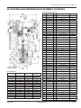
1
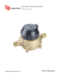
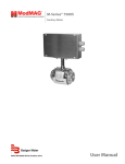
Ultra High Pressure Valve Assemblies
Type HP-60 (60,000 PSI) and Type HP-40 (40,000 PSI)
Shown with optional stainless steel actuator
RCV-UM-00570-EN-02 (August 2015)
User Manual
Ultra High Pressure Valve Assemblies, Type HP-60 (60,000 PSI) and Type HP-40 (40,000 PSI)
Page ii
RCV-UM-00570-EN-02
August 2015
User Manual
CONTENTS
Overview . . . . . . . . . . . . . . . . . . . . . . . . . . . . . . . . . . . . . . . . . . . . . . . . . . . . . . . . . . . . . . . . . . . . . . . . . . . 5
Component Descriptions . . . . . . . . . . . . . . . . . . . . . . . . . . . . . . . . . . . . . . . . . . . . . . . . . . . . . . . . . . . . . . . . . 5
Body/Bonnet Assembly . . . . . . . . . . . . . . . . . . . . . . . . . . . . . . . . . . . . . . . . . . . . . . . . . . . . . . . . . . . . . . . 5
Innervalve . . . . . . . . . . . . . . . . . . . . . . . . . . . . . . . . . . . . . . . . . . . . . . . . . . . . . . . . . . . . . . . . . . . . . . . . 5
Actuator . . . . . . . . . . . . . . . . . . . . . . . . . . . . . . . . . . . . . . . . . . . . . . . . . . . . . . . . . . . . . . . . . . . . . . . . . 5
Packing . . . . . . . . . . . . . . . . . . . . . . . . . . . . . . . . . . . . . . . . . . . . . . . . . . . . . . . . . . . . . . . . . . . . . . . . . 5
Unpacking & Inspection . . . . . . . . . . . . . . . . . . . . . . . . . . . . . . . . . . . . . . . . . . . . . . . . . . . . . . . . . . . . . . . . . . 5
Installation . . . . . . . . . . . . . . . . . . . . . . . . . . . . . . . . . . . . . . . . . . . . . . . . . . . . . . . . . . . . . . . . . . . . . . . . . . 5
Reorienting the Air Connections . . . . . . . . . . . . . . . . . . . . . . . . . . . . . . . . . . . . . . . . . . . . . . . . . . . . . . . . . . . . 6
Operation . . . . . . . . . . . . . . . . . . . . . . . . . . . . . . . . . . . . . . . . . . . . . . . . . . . . . . . . . . . . . . . . . . . . . . . . . . . 7
Adjusting the Closed Position . . . . . . . . . . . . . . . . . . . . . . . . . . . . . . . . . . . . . . . . . . . . . . . . . . . . . . . . . . . 7
Packing Adjustment for Hydro Testing 60,000 PSI Valves with Torlon/PFA Packing . . . . . . . . . . . . . . . . . . . . . . . . . . 7
Hydro Test Procedure / Packing Adjustment . . . . . . . . . . . . . . . . . . . . . . . . . . . . . . . . . . . . . . . . . . . . . . . . . . . . . 8
Packing Replacement and/or Innervalve Replacement . . . . . . . . . . . . . . . . . . . . . . . . . . . . . . . . . . . . . . . . . . . . . . 9
HP-60 Ultra High Pressure Valve Assembly (60,000 PSI) . . . . . . . . . . . . . . . . . . . . . . . . . . . . . . . . . . . . . . . . . . . . . 10
HP-40 Ultra High Pressure Valve Assembly (40,000 PSI) . . . . . . . . . . . . . . . . . . . . . . . . . . . . . . . . . . . . . . . . . . . . . . 11
August 2015
RCV-UM-00570-EN-02
Page iii
Ultra High Pressure Valve Assemblies, Type HP-60 (60,000 PSI) and Type HP-40 (40,000 PSI)
Page iv
RCV-UM-00570-EN-02
August 2015
Overview
OVERVIEW
This manual provides installation, operation and maintenance information relating to the HP-40 and HP-60 valve assemblies.
For operator safety and optimum performance, these instructions should be read, understood and followed. All technical
bulletins, drawings and literature pertaining to this design should be used with this manual.
COMPONENT DESCRIPTIONS
Body/Bonnet Assembly
• The lower portion of the unit is fitted into the pipeline.
• The body is a one-piece design containing the innervalve and packing set.
• The body is made of tri-axially forged 316 SST or 17-4PH H1150 SST.
Innervalve
• The needle (plug) and seat inside the body/bonnet assembly is the component which modulates the flow through the
valve as the actuator strokes.
NNOTE: The needle and seat are matched sets and should not be interchanged with other similar components, regardless
of labeling.
• The innervalve is made of wrought Stellite 6B (stem and plug with 416 SST upper adapter). If these components are gold
in color, they have been coated with titanium nitride.
Actuator
• The actuator sits atop the body/bonnet assembly and is connected to the body using a yoke locknut. The actuator may be
either Air-To-Open (ATO) Spring-To-Close or Air-To-Close (ATC) Spring-To-Open.
• An ATO actuator closes the valve upon a decreasing instrument signal or loss of signal. The ATC actuator opens the valve
upon a decreasing instrument signal, loss of signal or loss of air supply.
Packing
• The packing, a series of plastic rings, seals the stem of the valve, precluding leakage of the process media outside the
valve. The materials and orientation of the rings can vary from valve to valve.
• Refer to your customer drawing for orientation and material type.
VALVES OF THIS TYPE ARE TYPICALLY SUPPLIED WITH SOME FORM OF HIGH-PRESSURE PROCESS CONNECTION. BE
SURE TO USE PROPER MATING FITTINGS TO CONNECT THE VALVE TO PROCESS LINES. USING MISMATCHED FITTINGS
MAY RESULT IN DAMAGE TO THE BODY, LEAKAGE OR INJURY TO PERSONNEL.
UNPACKING & INSPECTION
Upon opening the shipping container, visually inspect the product and applicable accessories for any physical damage such
as scratches, loose or broken parts, or any other sign of damage that may have occurred during shipment.
NNOTE: If damage is found, request an inspection by the carrier’s agent within 48 hours of delivery and file a claim with the
carrier. A claim for equipment damage in transit is the sole responsibility of the purchaser.
INSTALLATION
NNOTE: In the following sections, the numbers in parenthesis refer to the item numbers on the drawings on page 10 and
page 11.
August 2015
RCV-UM-00570-EN-02
Page 5
Reorienting the Air Connections
1. For maintenance and servicing ease, the location selected for the valve assembly installation should allow for safe access
to both sides of the valve.
2. Remove any protective plugs or devices from the valve body, stem, positioner lever, and so on.
3. Do not remove the black hex pipe plug vent from the actuator housing, so to prevent debris from entering the spring side
of the housing during operation.
4. Make sure all lines are free of debris by flushing with fluid or blowing with clean air or other suitable gas, before
connecting any lines.
5. Suitable isolation valves should be installed upstream and downstream of the control valve.
6. Due the small size and close clearances of the innervalve, proper filtration of the process is recommended. If unsure about
filter size, contact the factory with the valves serial number and innervalve size.
7. Install the valve in the pipeline using mating fittings. Never mix fitting types or brands without prior knowledge
or experience.
8. If the unit is not equipped with a positioner, connect the instrument signal line to the connector located inside the
actuator housing:
• Lower port if Air-To-Open.
• Upper port if Air-To-Close.
9. If the unit is equipped with a positioner or other devices, make those connections according to the instructions for
the device.
DO NOT EXCEED AIR PRESSURE LIMITS.
• 90 PSIG FOR THE ACTUATOR (40…60 PSIG SHOULD BE SUFFICIENT FOR MOST APPLICATIONS).
• SEE SPECIFIC ACCESSORY MANUAL FOR OTHER DEVICES.
IF THE UNIT IS EQUIPPED WITH A POSITIONER (I/P TRANSDUCER, REGULATOR), IT HAS BEEN PRE-ADJUSTED AT THE
FACTORY. DO NOT ATTEMPT TO READJUST WITHOUT FIRST TESTING THE UNIT WITH THE PRESET SETTINGS.
REORIENTING THE AIR CONNECTIONS
Use the following procedure if the air connections must be reoriented and if the unit is an Air-To-Close (ATC) version:
1. Loosen the yoke lock nut (37) until the actuator can turn. Orient the unit as desired and retighten the yoke locknut.
2. If the unit is an Air-To-Open (ATO) version and must be reoriented. DO NOT simply rotate the actuator or damage the
innervalve (43) may occur.
3. Connect the control air and/or electrical signal lines to the I/P or positioner, so the valve can be stroked.
4. Signal the valve to raise the innervalve off the seat 10…30%.
5. Once the innervalve is off the seat, loosen the yoke locknut and orient the actuator as desired.
6. Retighten the yoke locknut.
7. De-stroke the valve, lowering the innervalve to the seated position.
8. If the unit is equipped with a positioner or other accessories, refer to its instruction for operation and adjustment.
9. Use a paste type sealant or clear grease for air connections. DO NOT use TFE tape, as small pieces of the tape may block the
small orifices in the devices. .
10.When stroking the valve, DO NOT remove the airline or electrical signal, as the unit to close rapidly, possibly damaging
the innervalve.
Page 6
RCV-UM-00570-EN-02
August 2015
Operation
NOTES:
• Although the valve will operate in any orientation, the vertical position is preferred for ease of maintenance and
adjustment.
• Proper bracing and support is recommended, due to the weight of the unit.
• Brackets may be factory ordered or fabricated and attached to one or more of the actuator rim screws.
OPERATION
Before subjecting the valve to process conditions, verify:
• The stroke function of the unit, to make sure the valve is stroking properly in response to the instrument signal.
• All accessories are functioning properly.
If the unit is ATO upon an increasing input signal, the valve will stroke and increase the flow through the pipeline. If the unit is
ATC, the valve will stroke and decrease the flow through the pipeline.
Adjusting the Closed Position
When in the closed position, the innervalve should achieve some level of shut-off, depending on innervalve size and required
tightness. Typically, linear innervalves sizes K-O should achieve ANSI Class IV and P sizes should achieve Class III.
The actuator is equipped with either three or six springs. During assembly of the actuator, a specific level of preload is
installed into the springs to achieve seating force on the innervalve. This preload is accomplished through the addition of
bushings of a specific thickness atop each spring.
NNOTE: Notice the two, long, hex “jack” screws and nuts across from each other at the actuator rim. As the springs are
preloaded, see the section on actuator disassembly, prior to loosening the jack screws.
Seat tightness is pre-adjusted at the factory; however, due to wear or repeated changing of the innervalve, seat tightness may
need to be adjusted.
To adjust the seating position or to achieve maximum tightness, use the following method:
NNOTE: Application of excess closing force can bend or damage the innervalve/stem, due to high potential actuator force.
1. By signaling the actuator, stroke the valve to approximately 10% off the seat.
2. Place a wrench on the stem flats (7) and loosen the jam nut (27).
3. Using a wrench on the stem connector (13), loosen the connection. Do not loosen (29).
4. Turn the stem adjustor clockwise, threading the adjustor up into the actuator stem, three or four turns.
5. Using the input signal, close the valve by decreasing (ATO) or increasing (ATC) the signal.
6. The valve should be adjusted to seat the innervalve at:
• Pneumatic Signal: 3.2 psig, if ATO and 14.9 psig if ATC.
• Electric Signal: 4.1 mA if ATO and 19.9 mA if ATC.
7. Once the signal is set, turn the stem connector counterclockwise until the innervalve makes contact with the seat. DO NOT
over-torque this adjustment or the seat may be damaged.
8. Holding the stem with a wrench, tighten the jam nut (27).
9. Reduce the signal to the minimum and conduct seat leak testing.
If leakage through the valve is excessive:
• Make sure the positioner is adjusted properly, causing the valve to be seated at the proper actuator signal.
• Replace the innervalve.
Packing Adjustment for Hydro Testing 60,000 PSI Valves with Torlon/PFA Packing
NNOTE: These specifications may also be used for 40,000 psi-rated valves, provided hydro pressures do not exceed
60,000 psig.
Customer pressures for 40 KSI valves should not exceed 40,000 psig. Factory hydro pressure should not exceed 60,000 psig.
Customer pressures for 60 KSI valves should not exceed 60,000 psig, or 90,000 psig for factory hydro.
NNOTE: Packing material and quantity of rings vary between the 40 and 60 KSI valves.
August 2015
RCV-UM-00570-EN-02
Page 7
Hydro Test Procedure / Packing Adjustment
HYDRO TEST PROCEDURE / PACKING ADJUSTMENT
1. Plug the outlet of test valve and connect the inlet to the hydro pump.
2. Stroke test valve to 20-50% open.
3. Open upstream valve, under low pressure (60…100 psig) to vent air until water leaks past the packing. If the packing does
not leak, slowly raise the pressure until water does leak.
4. Loosen the downstream plug until air is vented, then tighten.
5. Tighten packing gland (35) until water leakage stops.
6. Tighten the packing gland 1/16 inch turn past this point.
7. Slowly engage high pressure pump, stopping at 10,000 psig or whenever leakage occurs.
8. When leakage occurs or each increment is reached, reduce pressure to zero.
NEVER TIGHTEN THE PACKING GLAND WHILE THE VALVE IS UNDER PRESSURES HIGHER THAN 500 PSIG, AS DAMAGE
(GALL OR SEIZE) MAY OCCUR TO THE THREADS OF THE PACKING GLAND OR BODY.
9. Tighten the packing gland 1/16 inch turn.
10.Engage the high-pressure pump, stopping at the next 10,000 psig increment, or whenever leakage occurs.
11.Reduce test pressure to zero each time leakage occurs.
12.Tighten the packing gland approximately 1/16 inch turn.
13.Engage the high-pressure pump, stopping at the next 10,000 psig increment or whenever leakage occurs.
14.Reduce pressure to zero.
15.Tighten packing gland approximately 1/16 inch turn.
When the packing holds at 50,000 psig, the packing should hold between 60 KSI (for customer testing) or 90 KSI (for
factory testing). If the packing does not hold, repeat the above steps 9 through 12 until all leakage is stopped.
IIMPORTAN
• Sealing extremely high pressures is difficult at best.
• Although Teflon PFA is more resistant to cold flow (creep) than pure TFE, it is a plastic and possesses some cold flow.
• In addition to the forces applied to the packing by the gland, the system pressure also plays a part in sealing the packing
against the stem and the packing cavity wall.
• Some packing relaxation is not uncommon. Therefore, the packing should be tested when the valve is installed.
• The pressure should be raised carefully and in stages to check for leaks.
• If leaks occur, the pressure should be lowered to zero, the gland turned clockwise 1/16 inch turn, then retested.
• Do not attempt to tighten the gland while the valve is under high pressure.
• When packing has been used for any length of time at super pressures and then reduced to lower pressures, the packing
may leak when the pressure is then raised to higher pressures. If leakage occurs, some retightening may be necessary.
• If the valve is disassembled, always install new packing.
• Never reuse packing that has been removed from a used valve.
• If hydro-test is required to 90,000 psig, this high pressure will compress the packing to a point that it may not seal at
60,000 psig. After a 90,000 psig hydro-test is complete, replace with new packing, then test/tighten to suit the application.
• Since each valve and its components are different, packing gland torque numbers are unimportant. The best way to assure
a proper seal is careful testing and adjustment.
Page 8
RCV-UM-00570-EN-02
August 2015
Packing Replacement and/or Innervalve Replacement
PACKING REPLACEMENT AND/OR INNERVALVE REPLACEMENT
Valves with ratings of 40,000 psig and 60,000 psig, having a threaded lower adapter, are of similar construction. The stem
packing and innervalve loaded through the top of the body, with the seat loaded through the bottom of the body.
To replace the packing:
1. Remove the valve to a suitable workspace.
2. If the unit has an Air-To-Open actuator, raise the innervalve (43a) using air to offset the seat sufficiently to unthread the
innervalve stem from the actuator stem (7). Lay the actuator to the side, with the air pressure still on the diaphragm.
3. Once separated, loosen and remove the yoke lock nut and lift off the actuator.
4. Unthread the packing gland (35) and remove the innervalve.
5. Remove the lower threaded adapter (42) and slide the seat (43b) from the body (36).
6. Using a brass or aluminum rod up through the lower body cavity, gently tap the lower adapter until the packing
components loosen and fall out. Notice the order of each component as it falls out of the body cavity. At this point, the
upper packing follower (39) should come out easily.
7. Using the push rod, push the remaining packing cavity components from the packing cavity.
8. Clean and inspect the cavity using solvent and a soft brush. DO NOT use sandpaper or abrasives. Any visible marks can
cause leakage.
9. If damage to the bore is noticed, the body will need to be replaced.
10.Use silicone grease or Krytox lubrication on the lower packing adapter (38) and slide gently to the bottom.
11.Using a plastic tweezers, lower the first ring into the cavity bore sideways until the ring is inside the 0.375 inch bore, past
the threads and entrance.
12.Using a 1/8 inch diameter plastic rod, tip the ring over so that the concave side is pointing to the bottom of the cavity.
13.Using a 5/16 inch diameter plastic rod, push the ring to the bottom of the cavity.
14.Repeat the installation of all packing rings until they are all installed.
15.Insert the upper packing follower (39) into the cavity, on top of the last ring.
NNOTE: At this point, a new innervalve set may be installed.
16.Insert the innervalve into and through the packing.
17.Lubricate the packing gland threads and thread it into the body until it is finger tight.
18.Retract the innervalve to the upright position, until it bottoms inside the packing gland.
19.Install the seat into the bottom of the body, then thread the lower adapter until it is hand tight. A light coating of grease
will assist in insertion.
20.Stroke the innervalve (do not rotate) to check for alignment of the innervalve in the seat. If dragging occurs, do not
proceed until the innervalve can be replaced or inspected.
21.If the innervalve strokes smoothly, tighten the lower adapter to 100…125 pounds per foot. As the body wears from seat
replacement, the lower adapter may have to be tightened to 150 pounds per foot.
22.With the actuator still at stroke, reinstall the actuator, tighten the yoke lock nut and reconnect the innervalve to the
actuator stem.
23.Thread the stem adjustor all the way into the adjusting nut to keep the innervalve off the seat when air pressure
is removed.
24.Remove the air pressure from the actuator.
25.Carefully turn the stem adjusting nut counterclockwise until the innervalve just touches the seat.
26.Tighten any jam nuts.
27.Test and adjust packing according to previous instructions.
28.Consult the factory for instruction regarding disassembly of the actuator.
August 2015
RCV-UM-00570-EN-02
Page 9
HP-60 Ultra High Pressure Valve Assembly (60,000 PSI)
HP-60 ULTRA HIGH PRESSURE VALVE ASSEMBLY (60,000 PSI)
HP-60 Parts and Materials List
HP-60 Trim Chart
Trim Size
Max. Cv
Orifice Dia. (in.)
I*
J*
K
L
M
N
O
P-1
P-2
P-3
P-4
P-5
P-6
P-7
P-8
P-9
0.08
0.05
0.03
0.02
0.01
0.006
0.003
0.002
0.0013
0.001
0.0006
0.0004
0.00027
0.00018
0.00012
0.00008
0.1000
0.1000
0.0860
0.0860
0.0860
0.0860
0.0860
0.0625
0.0625
0.0625
0.0625
0.0625
0.0625
0.0625
0.0625
0.0625
* Special order
Page 10
Orifice Area
(sq. in.)
0.0079
0.0079
0.0058
0.0058
0.0058
0.0058
0.0058
0.0031
0.0031
0.0031
0.0031
0.0031
0.0031
0.0031
0.0031
0.0031
Item
Part No.
Qty
Description
Material
1
527588-0001
2
526041-0001
1
Yoke
Steel
1
Spring case
3
Steel
526042-0001
1
Pressure case
Steel
4
510031-0149
6
Spring
17-7 SST
5
512698-0002
1
Diaphragm
Buna-N
6
512883-0001
1
Retainer diaphragm
Steel
7
527448-0001
1
Stem
316/316L SST
8
512882-0001
1
Piston
Aluminum
9
400013-0085
1
Screw 5/16-24
Steel
10
527628-0001
1
Nut, travel stop
300 series SST
11
527589-0001
1
Stem connector
17-4 PH SST
12
512879-0003
1
Travel indicator
Nylon
13
520391
1
Connector 10-32
316/316L SST
14
400013-0002
10
Screw 5/16-18
300 series SST
15
430004-0021
12
Lock washer
300 series SST
16
410001-0060
10
Nut 5/16-18
300 series SST
17
430002-0107
24
Washer 5/16
300 series SST
18
512880-0001
1
Upper bushing
Nylatron
19
460019-0001
1
Lower bushing
Polymer
20
490018-0003
1
O-ring
Elf nitrile
21
512712-0001
1
Gasket
Carbon/nitrile
22
527233-0004
1
Travel scale
Aluminum
23
400006-0056
1
Set screw
300 series SST
24
512923-0001
1
Nameplate
300 series SST
25
526037-0001
1
Vent plug
Plastic
26
526119-0002
6
Screw 1/4-20
Steel/fluro
27
410001-0058
1
Nut 5/16-24
300 series SST
28
400001-0013
2
Screw 6-32
300 series SST
29
410011
1
Nut 10-32
300 series SST
30
527432-0001
1
Washer thrust
Steel
31
430004-0014
6
Lock washer 1/4
300 series SST
32
512717-0001
1
Caution decal
Mylar
33
512914-0002
1
Decal
Vinyl/mylar
34
544489-0001
1
Packing set
Torlon & PFA
35
522622-0003
1
Packing gland
300 series SST
36
529048-0001
1
Body & bonnet
17-4 PH SST
37
526328-0001
1
Yoke lock nut
316/316L SST
38
523185-0003
1
Adapter
17-4 PH SST
39
522774-0003
1
Follower
17-4 PH SST
40
522569
1
Adapter lock
Brass
41
400006-0045
1
Set screw
300 series SST
42
522694-0003
1
Lower adapter
17-4 PH SST
43a
—
1
Innervalve
—
43b
—
1
Seat
—
44
500458-0025
—
Grease
—
45
527624-0002
1
Spring spacer
PVC
46
528911-0001
1
Spacer
300 series SST
47
400013-0088
2
Screw
300 series SST
48
410001-0072
2
Nut
18-8 SST
49
501658-0001
1
Cap
Vinyl
RCV-UM-00570-EN-02
August 2015
HP-40 Ultra High Pressure Valve Assembly (40,000 PSI)
HP-40 ULTRA HIGH PRESSURE VALVE ASSEMBLY (40,000 PSI)
HP-40 Parts and Materials List
HP-40 Trim Chart
Trim Size
Max. Cv
Orifice Dia. (in.)
I*
J*
K
L
M
N
O
P-1
P-2
P-3
P-4
P-5
P-6
P-7
P-8
P-9
0.08
0.05
0.03
0.02
0.01
0.006
0.003
0.002
0.0013
0.001
0.0006
0.0004
0.00027
0.00018
0.00012
0.00008
0.1000
0.1000
0.0860
0.0860
0.0860
0.0860
0.0860
0.0625
0.0625
0.0625
0.0625
0.0625
0.0625
0.0625
0.0625
0.0625
* Special order
August 2015
Orifice Area
(sq. in.)
0.0079
0.0079
0.0058
0.0058
0.0058
0.0058
0.0058
0.0031
0.0031
0.0031
0.0031
0.0031
0.0031
0.0031
0.0031
0.0031
Item
Part No.
Qty
Description
Material
1
527588-0001
2
526041-0001
1
Yoke
Steel
1
Spring case
3
Steel
526042-0001
1
Pressure case
Steel
4
510031-0149
6
Spring
17-7 SST
5
512698-0002
1
Diaphragm
Buna-N
6
512883-0001
1
Retainer diaphragm
Steel
7
527448-0001
1
Stem
316/316L SST
8
512882-0001
1
Piston
Aluminum
9
400013-0085
1
Screw 5/16-24
Steel
10
527628-0001
1
Nut, travel stop
300 series SST
11
527589-0001
1
Stem connector
17-4 PH SST
12
512879-0003
1
Travel indicator
Nylon
13
520391
1
Connector 10-32
316/316L SST
14
400013-0002
10
Screw 5/16-18
300 series SST
15
430004-0021
12
Lock washer
300 series SST
16
410001-0060
10
Nut 5/16-18
300 series SST
17
430002-0107
24
Washer 5/16
300 series SST
18
512880-0001
1
Upper bushing
Nylatron
19
460019-0001
1
Lower bushing
Polymer
20
490018-0003
1
O-ring
Elf nitrile
21
512712-0001
1
Gasket
Carbon/nitrile
22
527233-0004
1
Travel scale
Aluminum
23
400006-0056
1
Set screw
300 series SST
24
512923-0001
1
Nameplate
300 series SST
25
526037-0001
1
Vent plug
Plastic
26
526119-0002
6
Screw 1/4-20
Steel/fluro
27
410001-0058
1
Nut 5/16-24
300 series SST
28
400001-0013
2
Screw 6-32
300 series SST
29
410011
1
Nut 10-32
300 series SST
30
527432-0001
1
Washer thrust
Steel
31
430004-0014
6
Lock washer 1/4
300 series SST
32
512717-0001
1
Caution decal
Mylar
33
512914-0002
1
Decal
Vinyl/mylar
34
544489-0001
1
Packing set
Torlon & PFA
35
522622-0003
1
Packing gland
300 series SST
36
529048-0001
1
Body & bonnet
17-4 PH SST
37
526328-0001
1
Yoke lock nut
316/316L SST
38
523185-0003
1
Adapter
17-4 PH SST
39
522774-0003
1
Follower
17-4 PH SST
40
522569
1
Adapter lock
Brass
41
400006-0045
1
Set screw
300 series SST
42
522694-0003
1
Lower adapter
17-4 PH SST
43a
—
1
Innervalve
—
43b
—
1
Seat
—
44
500458-0025
—
Grease
—
45
527624-0002
1
Spring spacer
PVC
46
528911-0001
1
Spacer
300 series SST
47
400013-0088
2
Screw
300 series SST
48
410001-0072
2
Nut
18-8 SST
49
501658-0001
1
Cap
Vinyl
RCV-UM-00570-EN-02
Page 11
Ultra High Pressure Valve Assemblies, Type HP-60 (60,000 PSI) and Type HP-40 (40,000 PSI)
Control. Manage. Optimize.
RESEARCH CONTROL is a registered trademark of Badger Meter, Inc. Other trademarks appearing in this document are the property of their respective entities. Due to continuous
research, product improvements and enhancements, Badger Meter reserves the right to change product or system specifications without notice, except to the extent an
outstanding contractual obligation exists. © 2015 Badger Meter, Inc. All rights reserved.
www.badgermeter.com
The Americas | Badger Meter | 4545 West Brown Deer Rd | PO Box 245036 | Milwaukee, WI 53224-9536 | 800-876-3837 | 414-355-0400
México | Badger Meter de las Americas, S.A. de C.V. | Pedro Luis Ogazón N°32 | Esq. Angelina N°24 | Colonia Guadalupe Inn | CP 01050 | México, DF | México | +52-55-5662-0882
Europe, Middle East and Africa | Badger Meter Europa GmbH | Nurtinger Str 76 | 72639 Neuffen | Germany | +49-7025-9208-0
Europe, Middle East Branch Office | Badger Meter Europe | PO Box 341442 | Dubai Silicon Oasis, Head Quarter Building, Wing C, Office #C209 | Dubai / UAE | +971-4-371 2503
Czech Republic | Badger Meter Czech Republic s.r.o. | Maříkova 2082/26 | 621 00 Brno, Czech Republic | +420-5-41420411
Slovakia | Badger Meter Slovakia s.r.o. | Racianska 109/B | 831 02 Bratislava, Slovakia | +421-2-44 63 83 01
Asia Pacific | Badger Meter | 80 Marine Parade Rd | 21-06 Parkway Parade | Singapore 449269 | +65-63464836
China | Badger Meter | 7-1202 | 99 Hangzhong Road | Minhang District | Shanghai | China 201101 | +86-21-5763 5412
Legacy Document Number: 941627